International Journal of Innovative Technology and Exploring Engineering (IJITEE) ISSN: 2278-3075, Volume-8 Issue-11, September 2019
Abstract: All modern manufacturing units are striving to develop a cost-effective product with optimized reduced weight by using CAE driven design process. In this scenario the product design is stimulated by structural optimization tools like geometrical (topology) optimization, shape optimization or size optimization. For conservation of natural resources and optimum energy utilization, weight reduction has been the main focus of machine tool manufacturers in the current state. Weight reduction can be achieved by the introduction of suitable material, manufacturing processes and design optimization. Geometrical optimization has developed an integral tool of product design and development. Geometry assisted design model gives optimized results which are better and innovative in terms of product design with improved structural performance and stability. Also, rapid prototyping has been used over traditional manufacturing and forming for the pattern making process which helps to reducing material wastage and time associated with tooling. The weight of guide bracket reduces from 2.7kg to 2.0kg. The maximum displacement is reducing from 0.016mm to 0.013mm.
Keywords : Horizontal band saw machine, rapid prototyping, optimization, topology.
I. INTRODUCTION
Weight reduction can be achieved by using the suitable material, manufacturing processes and design optimization. After the optimization results have been interpreted and smoothed (in the CAD system) analysis is carried out to verify the optimized components performance. Based on these results, another optimization step may follow, addressing questions related to change local geometry in order to reduce stress peaks [1].
In order to cut metal, sawing machine, namely power hacksaw and bandsaw are used. Reciprocating cutting action is effective in power hacksaw. Whereas continuous blade is used in band saw. Band saw blade revolve continuously, around a drive wheel in framed structure of bandsaw. The guide is adjusted to facilitating cutting action [2].
Revised Manuscript Received on September 03, 2019 * Correspondence Author
Dr. V. R. Naik*, Professor and Head, Department of Mechanical
Engineering, D. K. T. E. Society’s Textile and Engineering Institute, Ichalkaranji, Maharashtra, India, 41611,
V. B. Magdum, Assistant Professor, Department of Mechanical
Engineering, D. K. T. E. Society’s Textile and Engineering Institute, Ichalkaranji, Maharashtra, India, 416115,
A. P. Borkar, Assistant Professor, Department of Mechanical Engineering,
Walchand College of Engineering, Sangli, Maharashtra, India, 416415,
II. LITERATUREREVIEW
Emmanuil F. Kushnir et. al. [2001] mentioned common choices presently used for the main structural components of machine tools like steel, weldments, metal (cast iron) castings and polymer composites [3]. Waqas Saleem et. al. [2008] investigated nonparametric geometrical optimization which applied on a commercial aircraft vertical stabilizer component using ANSYS software. It was incidental that geometrical optimization fallouts in a better and innovative product design with improved structural performance and stability. S. Sánchez-Caballeroet et. al. [2011] introduced a method to reduce the structural weight subjected to multiple restrictions using Ansys workbench up to 50.2% was claimed [4]. D. M. Chauhan et. al. [2011] carried out weight reduction of hydraulic modular trailer frame by parametric optimization using ANSYS (APDL). Reduction in volume is taken as objective function. Von- Mises stress and deflection are taken as constraints. Finally frame is optimized and feasible design was obtained with 52 % reduction in mass [5]. K. Mallieswaran et. al. [2012] worked out on constantly increasing ecological concerns and demands for higher performance, lightweight construction equipment’s is a key factor to success mainly in the transportation sector but also in general engineering, machine tools, and architecture [6]. Tushar M. Patel et. al. [2013] carried out parametric optimization of Eicher 11.10 chassis frame to reduce weight. The chassis frame model was developed in Solid works and analyzed using ANSYS. The shear stress and deflection are measured for each set of parameters using FEA in ANSYS, finally 13.01% reduction in weight of chassis frame was claimed [7]. R. Rezaie et. al. [2013] investigates the issues and opportunities for the application of geometrical optimization methods. Converting geometrical optimization output files to usable AM input data for production of meso-scale structures for realizing intermediated density regions are investigated. This methodology is then implemented for the fused deposition modeling process (FDM). Weight plays a crucial role in many functional parts such as parts used in vehicle and aircraft industries [8]. Mohd Nizam Sudin et. al. [2014] aimed objective of reduction in weight of existing brake pedal of car using geometrical optimization. This was carried out Altair Optistruct software under linear static stress analysis. A new light with 22% less weight was developed without change in performance [9]. Ersan Gönül et. al. [2014] optimized the side walls of a large CNC portal milling machine made of cast iron by using ANSYS software. Here, geometrical optimization has been the most important tool in
Guide Bracket Optimization and
Guide Bracket Optimization and Manufacturing Using Rapid Prototyping
[image:2.595.355.497.121.232.2] [image:2.595.315.551.326.641.2]finding the optimal features of a cast part, such as optimal cross-section or number and arrangement of ribs. When compared with initial design, the weight of side wall decreased 75% by using ANSYS software [10]. Vinayak Kulkarni et. al. [2014] have reported, force estimation of suspension system components subjected to critical loading condition. The objective was weight and shape optimization [11]. Purushottam Dumbre et. al. [2014] stated about analysis of steering knuckle using finite element software. About 5% target of weight or mass reduction given without compromising on the structural strength [12]. Chuan Jiang et. al. [2015] expressed work mass of U-type structure decrease from 6kg to 4.94kg, which realizes the lightweight design U-type structure’s finite element model was solved by using Optistruct software [13]. Mahendra Shelar et al [2016] carried out analysis of steering knuckle with objective of reduction in weight. They achieved 8.1955 reduction in weight [14]. Jikai Liu et. al. [2016] stated manufacturing oriented geometrical optimization method is intended to provide useful insight classification and expert comments for the community [15]. Sandro L. Vatanabe et. al. [2016] addressed manufacturing constraints by means of a unified projection-based approach restricting the range of solutions to the geometrical optimization problem. The constraints like minimum member size, minimum hole size, symmetry, extrusion, pattern repetition, turning, casting, forging, and rolling are considered.The literature cited above provides information about different optimization parameters and design constraints to be considered while optimizing structural design as it is necessary to maintain the established critical parameters. The literature also focuses on reducing over designed variables and excess material distribution against cutting forces and loads which is very important for optimization of structural design. Literature review also emphasis on reducing traditional manufacturing processes over rapid prototyping for complex geometries which considerably reduces cost and time associated with tooling. It was stated that company want to optimize weight of some parts in their band saw machines without changing material and load bearing capacity. Company needed to optimize the weight of guide bracket for HBM 250 model which is used in stock (bar) supporting assembly (feeding system) as shown in Fig. 1.
Fig. 1. Stock bar supporting assembly
In this assembly 2 guide brackets are required. Rollers are used for carrying weight of stock bar which is going to be cut by bandsaw machine. But during cutting operation, stock bar is required to maintain a perpendicular position to cutting band saw. This can be done with the help of guide brackets.
Existing guide bracket weighs around 2.7 Kg of each (total 2*2.7=5.4 kg) and made of IS Standard grey cast iron (FG220) as shown in Fig. 2. Here objective is to reduce the weight of guide bracket by optimizing its structural design (for minimum material use).
Fig. 2. Original guide bracket
III. METHODOLOGYOFGUIDEBRACKET
OPTIMIZATIONANDMANUFACTURING
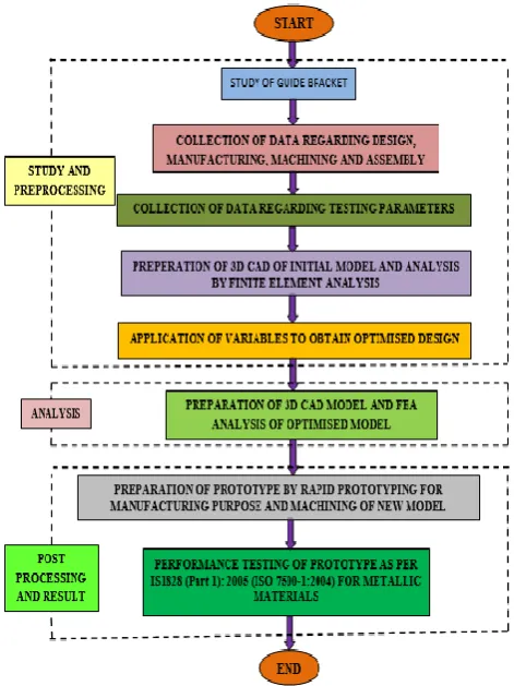
Fig. 3 shows flow chart of methodology of guide bracket optimization and manufacturing.
Fig. 3. Methodology of guide bracket optimization and manufacturing
Phase I:
• Collection of data in terms of material property, geometry, loads, manufacturing, machining, assembly method. • Making 3D model from drawing in available software 3D model such as CATIA.
• Pre-analysis of the component to find out stress distribution among excess
[image:2.595.46.280.577.701.2]International Journal of Innovative Technology and Exploring Engineering (IJITEE) ISSN: 2278-3075, Volume-8 Issue-11, September 2019
• Import 3D model in FEA software Altair Hyperworks and application of design variables.
• Geometrical optimization in suitable FEA software. Redesign guide bracket as per software results.
Phase II:
• Making 3D model of optimized model by using CAD software CATIA.
• FEA analysis of optimized model against magnitudes (stress, displacement) of initial model.
• Preparing prototype as per optimized design includes pattern making by using prototyping techniques and manufacturing of the model.
• Prototype performance testing/ validation for physical mechanical properties on universal testing machine as per IS1828 (Part 1): 2005 (ISO 7500-1:2004) for metallic materials.
IV. GUIDEBRACKETMANUFACTURING
[image:3.595.342.507.167.460.2]It was necessary to validate the optimized guide bracket against established operating conditions. For validating, SPM tools, Ichalkaranji allowed to conduct experimental test on actual casting prototype of optimized guide bracket. For this purpose, first CAD modelling of optimized guide bracket with draft, fillet and shrinkage allowance was prepared as shown in Fig. 4.
[image:3.595.62.271.324.664.2]Fig. 4. CAD model of optimized guide bracket
Fig. 5. CAD model generated using Cura work space
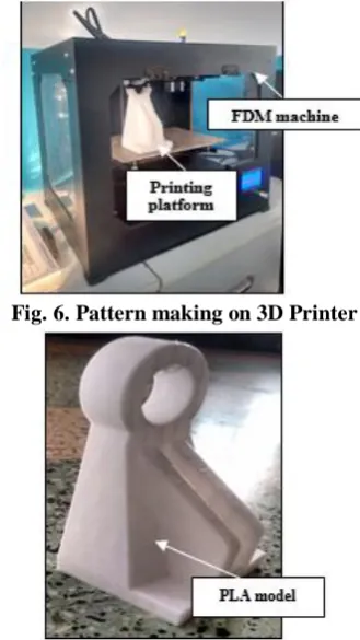
Prototype was developed by creating optimized guide bracket in CAD software as shown in Fig. 5. 3D CAD model of the guide bracket is sent to a FDM 3D printer for fabricating the geometry of guide bracket. The STL file of CAD model is processed in open source slicing software Cura as shown in Fig. 5, It generates code files for 3D printer. An extruder push, the plastic wire spool into a heated nozzle.
A guide move nozzle in X direction and platform in Y direction. Nozzle move in vertical Z direction, after layer completion. The thickness of layer was 0.01mm and printing speed 60mm/s. Path size capacity of the machine was 300mmx300mmx300mm.The wire made of PLA bio-plastic, is biodegradable and it can be used as pattern for no bake process. This plastic prototype of guide bracket as shown in Fig.7. Six hours were required to fabricate the prototype and total weight of prototype was 140 gms.
Fig. 6. Pattern making on 3D Printer
Fig. 7. Pattern manufactured by fused deposition method
Casting manufacturing
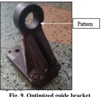
Pattern was manufactured in Top Gear Industries, Ichalkaranji by using sand casting method. Casting of optimized guide bracket shown in Fig. 8 and Fig. 9.
[image:3.595.68.268.523.667.2] [image:3.595.344.510.540.686.2]Guide Bracket Optimization and Manufacturing Using Rapid Prototyping
Fig. 9. Optimized guide bracket sValidation of specimen:
[image:4.595.325.530.145.490.2]Universal testing machine (UTM) as shown in Fig. 10. was used to test the tensile stress, compressive strength of material. It is named after the fact that, it can perform any standard tensile and compressive tests on materials, components and structures. Testing was carried out on computerized universal testing machine (TUE-C) at Atlanta metallurgical services, Kolhapur as per testing code IS 1828:2005 (ISO 7500-1:2004) [16]. The load applied was 388N.
Fig. 10. Guide bracket testing on universal testing machine
[image:4.595.64.275.353.545.2]Result comparison:
Table No. 1. Result comparison between theoretical and actual testing
Sr. No.
Strain in numerical analysis (Hyperworks
software)
Strain in experimental test
(UTM test)
1 0.013 mm
0.010 mm (approximately from
graph)
Both numerical and experimental results are too much closer to each other so validation of optimized guide bracket is completed.
V. RESULTANDDISCUSSION
Graphs generated on UTM for old guide bracket and new guide bracket are shown in Fig. 11 and Fig, 12 respectively. Validation of the work has been done by UTM machine by applying 1.5 times more load than the company recommendation. So here also optimized guide bracket has maximum displacement value too much near about FEA analysis value.
Fig. 11. Graph generated for old guide bracket
Fig. 12. Graph generated for optimized guide bracket
Comparison of guide bracket before and after optimization shown in Table2.
Table No. 2. Comparison before and after optimization
Parameters Before
optimization
After optimization
Maximum displacement
(mm) 0.016 0.013
Von Mises stress- Maximum Stress
(N/mm2)
9.506 11.618
Weight (kg) 2.7 2
Reduction in weight 2.7-2=0.7 kg (26%)
The structural analysis as well as optimization of guide bracket has been carried out in Hyperworks and the performance of optimized guide bracket prototype is then validated as per company standards on UTM testing machine. From the analyzed
[image:4.595.49.289.595.700.2]International Journal of Innovative Technology and Exploring Engineering (IJITEE) ISSN: 2278-3075, Volume-8 Issue-11, September 2019
1) The maximum Von Mises stress and maximum displacement are lesser than safe limit. Initial Von Mises Stress was 9.506 N/mm2 and the Final Von Mises Stress is 11.618 N/mm2.
Initial displacement was 0.016 mm and final displacement is 0.013 mm.
2) The geometrical optimization yield, optimization geometry for load and constraints under consideration. Initial weight was 2.7 kg and final weight was 2 kg (26% reduction).
3) From the graph generated by UTM testing, it was observed that the optimum guide bracket withstands the actual working loading conditions (388 N). The actual displacement obtained after UTM testing is 0.010 mm which is almost near about the analytical results and displacement value of current guide bracket (0.016 mm). From the graph it is clear that the optimized guide bracket fulfils the actual working conditions of current guide bracket after doing performance validation as per the company requirement and standard.
VI. CONCLUSION
In the present work, optimization of guide bracket was carried out without any compromise of load bearing capacity for band saw machine. The bracket was optimized and developed using rapid prototyping for its pattern. The modified guide bracket was tested for its application and satisfactory results were obtained. The guide bracket weight and maximum displacement reduces from 2.7kg to 2.0kg and from 0.016mm to 0.013mm respectively. 3D printing or rapid prototyping technology helped in accelerating the new product development cycle. It’s a powerful tool for building prototypes directly from the CAD model. The 3D printed parts provide same size prototypes and it can be directly used as a pattern which reduces manufacturing time. Geometric optimization is powerful tool used for weight optimization.
ACKNOWLEDGMENT
Authors are thankful to SPM Tools, Ichalkaranji to sponsor this work and also sparing their support facilities and infrastructure to carry out this work.
REFERENCES
1. Waqas Saleem, Fan Yuqing, Wang Yunqiao, Application of Topology Optimization and Manufacturing Simulations – A new trend in design of Aircraft components, Proceedings of the „International Multi-Conference of Engineers and Computer Scientists, Volume II, 19-21 March, 2008 2. Sandro L. Vatanabe, Tiago N. Lippi, CíceroR.de Lima, GlaucioH.
Paulino, Emílio C.N. Silva, Topology optimization with manufacturing constraints: A unified projection-based approach, Advances in Engineering Software journal, 2016, page no. 97–112.
3. Emmanuil F. Kushnir; Mahendra R. Patel; Terrence M. Sheehan, Material Considerations in Optimization of Machine Tool Structure, Proceedings of 2001 ASME International Mechanical Engineering Congress and Exposition November 11–16, 2001, New York, NY.
4. S. Sánchez-Caballero, M.A. Selles, R. Pla-Ferrando, E. Pérez-Bernabeu’ Weight reduction in structures using finite elements and multi objective genetic algorithms, ANNALS of the Oradea University. Fascicle of Management and Technological Engineering, Volume X (XX), 2011. 5. D. M. Chauhan, Prof. S. B. Soni and Prof. A. M. Gohil, Parametric
Optimization of Hydraulic Modular Trailer Frame using ANSYS (APDL),
Institute of technology‟, Nirma University, Ahmadabad – 382 481, December 2011.
6. K. Mallieswaran, Samad Arbaaz Anjum and A. Pradeep, Case Study on
manufacturing of Light Weight Component by Metal Forming, published in „Journal of Advanced Technology in engineering‟, Vol. 1, December 2012. Pages: 63-70.
7. Tushar M. Patel, Dr. M. G. Bhatt and Harshad K. Patel, Parametric Optimization of Eicher 11.10 Chassis Frame for Weight Reduction Using FEA-DOE Hybrid Modeling, International Journal of IOSR Journal of Mechanical and Civil Engineering (IOSR-JMCE), e-ISSN: 2278-1684, p-ISSN: 2320-334X, Volume 6, Issue 2 (Mar. – Apr. 2013), PP 92-100. 8. R. Rezaie, M. Badrossamay, A. Ghaie, H. Moosavi, Topology optimization
for fused deposition modeling process, The 17th CIRP Conference on Electro Physical and Chemical Machining (ISEM)’Procedia CIRP 6, 2013, page no. 521 – 526.
9. Mohd Nizam Sudin, Musthafah Mohd Tahir, Faiz Redza Ramli, Shamsul
Anuar Shamsuddin, Topology Optimization in Automotive Brake Pedal Redesign, International Journal of Engineering and Technology (IJET) ISSN : 0975-4024 Vol 6 No 1 Feb-Mar 2014 398.
10. Ersan Gönül, Muhsin Kılıc, and Fatih Karpat, A Study on Design and Manufacturing for the Side Wall of Large CNC Portal Milling Machine, 2nd International Conference on Research in Science, Engineering and Technology (ICRSET’2014), March 21-22, Dubai (UAE) 2014 11. Vinayak Kulkarni, Anil Jadhav, P. Basker, Finite Element Analysis and
Topology Otimization of Lower Arm of Double Wishbone Suspension using RADIOSS and Optistruct, International Journal of Science and Research (IJSR), Volume 3 Issue 5, May 2014.
12. Purushottam Dumbre, Prof A.K.Mishra, V.S.Aher, Swapnil S. Kulkarni,
Structural Analysis of steering knuckle for weight reduction, International
Journal of Advanced Engineering Research and Studies,
E-ISSN2249–8974Int. J. Adv. Engg. Res. Studies/III/III/April-June, 2014.
13. Chuan Jiang, Hongyi Hu, Zhizhou Xu, Ruzhen Liu, The U-type Platform
Multi-objective Topology Optimization Research, 4th International Conference on Computer, Mechatronics, Control and Electronic Engineering (ICCMCEE 2015), 2015.
14. Mahendra Shelar, Optimization of Steering Knuckle using DOE,
International Journal on Mechanical Engineering and Robotics (IJMER), ISSN (Print): 2321-5747, Volume-4, Issue-1, 2016
15. Jikai Liu, Yongsheng Ma, A survey of manufacturing-oriented topology optimization methods, Advances in Engineering Software journal, 2016, page no. 161–175.
16. National Accreditation Board for Testing and Calibration Laboratories: specific criteria for calibration laboratories in mechanical discipline: UTM, Tension Creep and Torsion testing machine issue no.: 05 issue date: 12.08.2014.
AUTHORSPROFILE
Dr. V. R. Naik Ph. D. in Mechanical Engineering. He
had published more than 70 papers in journals and conferences. He has 6 years of industrial and 24 years of academic experience.
V. B. Magdum M. E. in Mechanical Engineering and
pursuing Ph. D. He had published 8 papers in journals and conferences. He has 3 years of industrial and 9 years of academic experience.
A. P. Borkar M. E. in Mechanical Engineering He had