Abstract: A compact egg-shaped super wide-band patch antenna with coplanar waveguide (CPW) feed is proposed. A much simpler design equation has been identified compared to previous reported works for egg-shaped patch antennas. An optimized egg shaped antenna has been designed and implemented on FR4 substrate with the dimensions 30mm x 27.5mm x 1.6mm.The antenna with geometry modifications has an impedance bandwidth 2.85-31.6 GHz. The performance of the antenna was validated analytically for super wideband (SWB) operation and experimentally for ultra-wideband (UWB) operation. A maximum gain of 4.4dBi and a minimum of 2dBi was observed at 6.5GHz and 3GHz respectively. A 30% reduction in patch area has been achieved compared to existing egg-shaped SWB antennas in literature. The lower frequency bound of the antenna is scalable with dimensions for lesser permittivity substrates which has been analytically validated. It is identified that the proposed antenna design could be used to achieve flexibility in bandwidth. This antenna is a potential candidate for super wideband applications.
Keywords : Compact, co-planar waveguide, egg-shaped patch, modified ground plane, , super wide-band, ultra-wideband.
I. INTRODUCTION
The demand for extremely large bandwidth and high data rates in modern wireless communication for military and civilian applications has led to the development of ultra-wideband (UWB) and super-wideband (SWB) antennas. UWB antennas with a bandwidth ratio of 3.42:1, have become defunct in capability due to growing needs of higher capacity and data rates in multitudes of communication systems. In 1960‟s Rumsey [1] developed a family of antennas classified as frequency independent antennas. SWB antennas have a bandwidth ratio of 10:1 or greater. SWB technology has ubiquitous applications in modern wireless communication systems. SWB antennas provide improved resolution and ranging, higher time precision, increased capacity and data rates compared to UWB. Planar monopole antennas are preferred for realizing SWB characteristics due to their smaller dimensions and easier integration with microwave IC‟s. SWB antennas
Revised Manuscript Received on October 05, 2019. * Correspondence Author
Philip Cherian*,Division of Electronics Engineering, School of Engineering, Cochin University of Science and Technology (CUSAT), Cochin India,. Email: philip28cherian@cusat.ac.in
Anjit T. A., Division of Electronics Engineering, School of Engineering,(CUSAT), Cochin, India. Email: taanjit@yahoo.in
Mythili P., Division of Electronics Engineering, School of Engineering,(CUSAT), Cochin, India. Email: mythili9999@gmail.com.
are used for UWB, Radio determination applications (4.5 – 7 GHz), ( 13.4 – 14 GHz), Wireless access systems/Radio LAN (17.1 - 17.3 GHz), Doppler navigational aids, Radio astronomy (22.5 GHz, 24.05 - 27 GHz), Short range radar (21.4 - 27 GHz), ISM (24.25 GHz), UWB Vehicular Radar(22-29 GHz) [13] and more.
Several techniques in the geometry have been proposed in literature to achieve super wideband performance. SWB antennas have been implemented in different configurations such as metal plate monopoles, printed monopoles and printed slot antenna configurations as reviewed by Zhong S. et.al. [2]. Printed monopoles and printed slot antenna configurations have been preferred due to their compactness and easier integration. The super-wideband antennas reported in [3]–[7] have dimensions which correspond to the lower frequency bound from 0.4 GHz to 1.3GHz. To achieve increased bandwidth, the thinner substrate used in these antennas has lower permittivity. In [8] an SWB antenna have been reported with complex fractal patch geometry on thinner and lower dielectric permittivity substrate which have lower bound frequency near 2GHz and subsequent reduction in size. On the same type of substrate, a tapered microstrip fed circular ring radiating patch with round cornered ground plane has been implemented in [9] to obtain a lower bound frequency of 1.6 GHz. A SWB antenna on FR4 substrate have been reported in [10] with an offset fed egg shaped patch having fractal ground plane and in [11] with a microstrip fed clover shaped radiating patch. Using the same substrate and co-planar waveguide (CPW) feed, a partially egg shaped slot antenna [12] and a fractal radiating patch antenna [13] has also been reported.
This paper investigates to find a simple equation to design a SWB antenna with the geometry based on the natural shape of an egg. The optimized dimensions are compact compared to the above reported egg shaped antennas. A square slot is provided in the ground plane at the gap between CPW feed and ground plane to improve the reflection coefficient and to obtain the higher bound of the impedance bandwidth which has not been reported in the literature. The two aspects mentioned above are the novelty of this paper. An L-shaped stub is incorporated into the radiating patch to adjust the lower edge of the ultra-wideband. Section 2 discusses the design equations of the proposed egg-shaped geometry and its adaptation for the design of the radiating patch of the antenna along with detailed dimensions of the antenna geometry. Section 3 deals with the analysis of the features of the proposed antenna based on the results of simulation followed by the experimental results in Section 4. Section 5 concludes the paper.
A Modified Avian Egg Shaped CPW Fed Printed
Monopole for SWB Applications
II. ANTENNA DESIGN
The geometry of the proposed egg shaped radiating patch is shown in Fig.1. This geometry is based on the design equations proposed by Nobuo Yamamoto [14]. Though different design equations were suggested, the simplest design equation which could be adopted for the antenna design are given as (1) and (2). The parameters a, band ccan be varied for achieving the desired shape.
Fig. 2 (a), (b) shows the family of egg-shaped geometries for a set of typical values of a and b with c = 1 and c = 2. Avian eggs have a wide variety of shapes ranging from spherical to elliptical and pointed asymmetric shapes [15]. Even though the shape of an egg does not have a traditionally defined shape class, a study was made with combinations of a, b and c for the most common shape among avian species defined by equations (1) and (2).Certain conditions are formulated in this work with the parameters a, b and c for the design of egg shaped patch antenna and are obtained as
[image:2.595.59.255.164.404.2] [image:2.595.313.561.287.650.2](i) a, b ≠ 0
(ii) 0.6|a| ≤ |b| ≤ 0.8|a| (iii) c ≤ 0.2|a |
The dimensions of a typical egg shaped patch antenna are shown in Fig. 3. The height of the radiating patch is „2a‟ which determines the lower edge frequency of the antenna. The girth of the egg-shaped radiating patch ‟w1‟is twice the maximum value of y given by the design equation (2).The feed height above the top edge of the ground plane is „h1‟. The ground plane has a curvature with a height „h2‟.The total height of the ground plane is „h2+h3‟. The CPW feed placed symmetrically in the middle of the ground plane has a width „w2‟ with gap „g‟. The above dimensions are to be optimized for maximum bandwidth.
III. ANTENNA SIMULATION AND ANALYSIS The proposed antenna has been implemented in FEM based HFSS. The antenna patch is designed on a substrate with
r
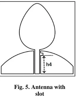
=4.4 and thickness 1.6 mm. The patch is fed by a 2 mm wide 50Ω CPW line. The radius of curvature of the upper edge of the ground plane near to the radiating patch is 20 mm. Parametric analysis was carried out for various combinations of a, b and c. The simulated reflection coefficient characteristics in the band from 2 – 30 GHz for four sample values of a, band c are shown in Fig. 4. The number of plots in the figure is limited to four for the sake of clarity. It can be seen that as the value of „a‟ and „b‟ increase, height and girth of the egg shaped patch increases, the lower edge frequency decreases and subsequently notches appear in the band. Based on the results of parametric analysis, the dimensions of the antenna for an optimum size were fixed at a = 10, b = 7 and c = 2. The bandwidth of the corresponding antenna excluding the notch at 4-5.55 GHz, extends from 2.92 GHz to 26 GHz.To eliminate the notches, a square shaped slot was introduced in the ground plane adjacent to the feed gap at a height „h4‟ from the feed end (see Fig. 5). A analysis was performed on the parameter „h4‟, position of the slot as shown in Fig. 6. It is seen that the reflection coefficient characteristic improves for increasing values of „h4‟and is optimum at 8mm.The resultant bandwidth starts from 3.16 GHz and extends till 31.6 GHz. The introduction of a slot in the ground plane shifts the lower
edge frequency from 2.92 GHz to 3.16 GHz which has to be reduced Fig. 1. Geometry of an egg
y = 𝑎 sinθ (2)
where 𝑎 = ( 𝑏 + 𝑐 cosθ )
(i)
(ii)
Fig. 2. Family of geometries for (i) c = 1 and (ii) c = 2 (i)
(ii)
Fig. 2. Family of geometries for (i) c = 1 and (ii) c = 2 (i)
(i) (i)
Fig. 2 (a), (b). Family of geometries for (a) c=1 and (b) c = 2 (a)
to a value less than or equal to 3.1GHz. An L-shaped stub of height „h5‟ was introduced with a protruding strip of length „w3‟ from the
radiating patch as shown in Fig. 7 for this purpose. The position and length of the stub on the egg shaped patch has been optimized independently after parametric analysis. The
length of the strip „w3‟ is obtained as 4mm and the width of the stub and strip is fixed at 1 mm.
The height „h6‟ of the stub from the feed edge is optimized at 17mm. The effect of the variation in stub length on the lower band edge frequency is shown in Fig. 8. It can be seen that the increase in the length of the stub shifts the lower edge frequency to a lower value. The lower edge frequency corresponding to the optimum „h5‟ (13mm) is 2.85 GHz. A comparison has been made between the basic egg shape antenna and the modified versions in Fig. 9 which shows the simulated return loss plots for (i) the basic egg-shaped patch antenna (ii) the patch antenna with slot in the ground plane
(iii) the patch with stub and slot. From the figure, it is evident that the antenna bandwidth with all optimized dimensions extends from 2.85 GHz to 31.6 GHz which covers the entire super high frequency band inclusive of ultra-wideband.
[image:3.595.42.271.101.515.2]The optimized antenna dimensions are given in Table I. It is observed that the dimensions of the antenna are reduced by 30% compared to those with same geometry reported in literature [10], [12].This antenna has a ratio bandwidth (RB) of 11.04.
Fig. 3. Antenna dimensions (mm)
[image:3.595.306.548.213.603.2]Fig. 4. Reflection coefficient for sample values of a, b and c
Fig. 5. Antenna with slot
[image:3.595.96.225.543.710.2]The current densities of the antenna at different frequencies of SWB are shown in the Fig. 10(a)–(c). It is seen that at 3.2 GHz, the currents are concentrated at the L-shaped stub and at the lower periphery of the egg-shaped patch near to the CPW feed. The effect of the slot is profound for the middle and higher frequencies of the band and current variations are evident along the periphery of the patch and the modified ground plane.
A comparison of the proposed design is made with earlier works in the literature using FR4 substrate as shown in the Table II. It can be seen in [10], [11], that the microstrip fed antennas has sizes larger than the proposed antenna with CPW feed. The upper bound frequency of the proposed antenna is greater than that in [12] with egg-curved slot geometry and the lower bound frequency accommodates UWB compared to [13] with the same dimensions.
The proposed antenna uses a commonly available cheaper substrate FR4 than antennas in [3]-[9]. The reflection coefficient of the proposed antenna was simulated for substrate (TLY-5A) with permittivity
r =
2.2and 0.757 mm thickness for increased dimensions and the results are plotted in Fig. 11.The corresponding antenna size and the achieved bandwidths are compared in Table III with antennas reported in literature on the bandwidth to dimension ratio (BDR) [10]. For fair comparison, recent antennas with similar lower frequency bound are considered. The results show that the antenna design is scalable to the lower frequency bound, bandwidth of interest as per requirement with change in dimensions and substrate and can accommodate different frequency bands.
Ref. No. (Year)
Dimensions (mm3)
Bandwidth (GHz) [10] (2011) 35 x 77 x 1.6 1.44 – 18.8 [11] (2017) 50 x 45 x 1.6 1.9 - 30 [12] (2014) 40 x 40 x 1.6 1.95 - 20 [13] (2016) 30 x 28 x 1.6 3.4 – 37.4
Proposed antenna
30 x 27.5 x 1.6 2.85 – 31.4 Table- II: Comparison with previous works
Fig. 10(a) – (c) Current density (a) 3.2 GHz
(c) 30 GHz
[image:4.595.313.557.54.398.2](b) 15 GHz
Fig. 8. Reflection coefficient for different values of h5
[image:4.595.49.274.264.423.2]h1 0.5 w1 15.1 h4 8 w 2 h2 6.22 w2 12.5 h5 13 2a 20 h3 3.28 w3 4 h6 17 g 0.25
Table- I: Optimized dimensions [mm]
[image:4.595.31.271.455.738.2]IV. EXPERIMENT RESULTS AND DISCUSSION The proposed antenna was fabricated on an FR4 substrate (r=4.4) of thickness 1.6mm with dimensions 30mm x 27.5mm as shown in Fig. 12 and the antenna performance was measured with a Vector Network Analyzer “Agilent PNAE8362B” available in the institution. The measurements were confined to 11GHz due to limitations of the equipment. Fig. 13 shows the comparison of reflection coefficient between simulation and experiment. The lower edge frequency from simulation is 2.85 GHz and the experiment result is at 3.06 GHz with the impedance bandwidth for measurement case limited to 20 GHz. The shift in the lower edge frequency and resonances are attributed to the tolerances in fabrication. It can be observed that the results are in close agreement till 20 GHz. The gain of the antenna was measured upto 11GHz and is shown in Fig. 14. It is seen that the gain of the antenna increases towards the centre of the ultra-wideband and remains
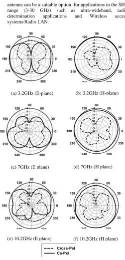
steady for the upper half of the band with an overall variation from 2 to 4.4 dBi. The peak gain is observed at approximately 5.5 GHz to 6.5 GHz. The radiation pattern of the proposed antenna was measured up to 11GHz in both the E and H planes and are shown in the Fig. 15(a) to (f) for the frequencies 3.2 GHz, 7 GHz and 10.2 GHz. The H-pattern is almost omnidirectional and the E-pattern is nearly doughnut shaped in the band.
V. CONCLUSION
A compact CPW fed modified egg-shaped monopole antenna, with ground plane having a square slot and an L-shaped stub is proposed for super-wideband applications. The antenna fabricated was experimentally investigated. The modified design with a bandwidth ratio of 11.04:1 covers super-wideband operation. The proposed design is simpler and more compact compared to
the earlier works reported in literature. The proposed
[image:5.595.301.533.61.379.2]Fig. 14 Measured antenna gain [Fig. 4. Reflection coefficient for sample values of a, b and c
Fig. 13 Experimental versus simulated reflection coefficient
Fig. 12 Fabricated antenna
[image:5.595.43.268.64.239.2]x = 𝑎 cosθ (1)
Fig. 11 Reflection coefficient for different antenna sizes
Table- III: Comparison of dimensions and bandwidth of the egg-shaped antenna with earlier
works in literature
Proposed Antenna
BDR
Antennas reported
BDR
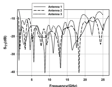
(Antenna 1) 45x40x0.757 mm3 (1.9 – 26.12) GHz
2394 [11]
50x45x1.6 mm3 (1.95 – 20) GHz
1935
(Antenna 2) 60x44.5x0.757 mm3
(1.5 – 21.43)GHz
2775 [10]
77x35x1.6 mm3 (1.44 – 18.8) GHz
2771
(Antenna 3) 90x67x0.757 mm3
(1 – 18.77) GHz
2683 [6]
130x120x1.1 mm3 (1.18 – 49.22)
GHz
[image:5.595.325.523.398.529.2]antenna can be a suitable option for applications in the SHF range (3-30 GHz) such as ultra-wideband, radio determination applications and Wireless access systems/Radio LAN.
ACKNOWLEDGMENT
The author(s) are thankful to Professor. P. Mohanan at Centre for Research in Electromagnetics and Antennas(CREMA), Cochin University of Science and Technology, Cochin for his support in extending the facilities and help for the completion of this work.
REFERENCES
1. V.H. Rumsey, Frequency independent antenna, New York: Academic Press, 1966, ISSN 0018-926X.
2. S. Zhong, J. Liu, C. Du, and L. Xue, “SWB planar antenna technology,” In IEEE China-Japan Joint Microwave Conference Sept. 2008, DOI: 10.1109/ CJMW .2008.4772392.
3. S. Zhong, X. Liang, and W. Wang, “Compact elliptical monopole antenna with impedance bandwidth in excess of 21:1,”
4. IEEE Transactions on Antennas and Propagation, Vol. 55, No. 11, November 2007, pp.3082-3085.
5. D. Yuandan, H. Wei, L. Leilei, Z. Yan, and K. Zhenqi, “Performance analysis of a printed super-wideband antenna,” Microwave And Optical Technology Letters, Vol. 51, No. 4, April 2009, pp. 949-955.
6. J. Liu, K.P. Esselle, S.G. Hay, Z. Sun, and S. Zhong, ”A Compact super-wideband antenna pair with polarization diversity,” IEEE Antennas And Wireless Propagation Letters, Vol. 12, 2013, pp. 1472 – 1475.
7. T. Son, K. Gina., and C. H. Keum,”Planar Super Wideband Loop Antenna with asymmetric coplanar strip feed,” Electronics Letters, Vol 52, No. 2, Jan 2016, pp. 96-98.
8. M. Samsuzzaman and M. T. Islam, “ A Semi-circular Shaped Super wideband Patch Antenna with High Bandwidth Dimension Ratio,” Microwave And Optical Technology Letters, Vol. 57, No. 2, February 2015. pp. 445-452.
9. M.A. Dorostkar, M.T. Islam, and R. Azim, “Design Of A Novel Super Wide Band Circular hexagonal Fractal Antenna,” Progress In Electromagnetics Research, Vol. 139, 229–245, 2013.
10. M. Manohar, R.S. Kshetrimayum, and A.K. Gogoi, “A compact dual band notched circular ring printed monopole antenna for super-wideband applications,” Radio Engineering, Vol. 26, No. 1, April 2017, pp. 64-70.
11. K.-R. Chen, C.-Y.-S. Desmond, and J.-S. Row, “A compact monopole antenna for super wideband applications,” IEEE Antennas and Wireless Propagation Letters, Vol. 10, 2011, Pages 488-491.
12. S.K. Palaniswamy, et. al., “Super wideband printed monopole antenna for ultra wideband application,” International Journal of Microwave and Wireless Technologies, Volume 9, Issue 1, February 2017 , pp. 133-141.
13. S. Verma, and P. Kumar, “Printed Egg Curved Slot Antennas for Wideband Applications,” Progress in Electromagnetics Research B, Vol. 58, 111-121, 2014.
14. S. Singhal, and A. K. Singh, “CPW fed Hexagonal Sierpinski super wideband fractal antenna,” IET Microwaves Antenna and Propagation, Vol. 10, Issue 15, pp. 1701–1707, 2016. 15. N. Yamamoto, Equation of egg shaped curves, TDCC
Laboratory, ISBN: 978-4-88142-516-9, Edition A5, April, 2011. 16. [15] M.C. Stoddard et.al., “Avian Egg shape: Form, function
and evolution,” Science 2017, Issue: June 23;356(6344): pp. 1249 – 1254, doi: 10.1126/science.aaj 1945.
AUTHORS PROFILE
Anjit T. Agamanandan was born in Aluva, Kerala, India in 1986. He graduated with B.Tech degree from Mahatma Gandhi University, Kottayam in 2008 and his completed his post-graduation with M.Tech degree from Kerala University, Thiruvanthapuram in 2011.He is a research scholar at Division of Electronics Engineering, School of Engineering, CUSAT, Cochin, India. His research interests include compressive sensing, microwave imaging, signal processing, and optimization techniques.
(a) 3.2GHz (E-plane) (b) 3.2GHz (H-plane)
(c) 7GHz (E plane)
(f) 10.2GHz (H plane) (e) 10.2GHz (E plane)
Fig. 15(a) - (f) Normalized Radiation patterns (d) 7GHz (H plane)
[image:6.595.32.284.47.570.2]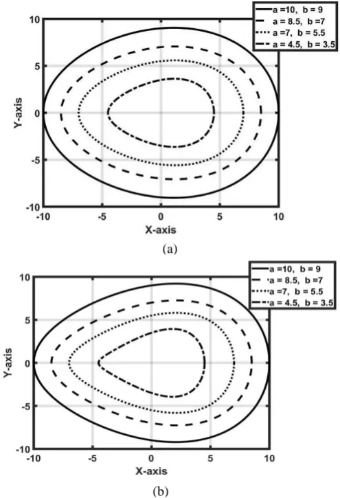
![Table- I: Optimized dimensions [mm]](https://thumb-us.123doks.com/thumbv2/123dok_us/8166286.251046/4.595.31.271.455.738/table-i-optimized-dimensions-mm.webp)