Abstract: Flow through vaneless diffuser in the centrifugal compressor stage is studied at varied flow conditions using finite volume method based commercial code, ANSYS CFX. The contour of static pressure, stagnation pressure, absolute velocity, as well as meridional velocity divulges the nature of flow that happens in the centrifugal compressor stage. Circumferential non-uniformity due “jet-wake” formation is seen at the impeller exit. These lead to mixing of fluid having varied energy levels which happens within the vaneless diffuser. Total pressure rises along the radius ratio and its distribution is higher near the shroud for all flow conditions. Absolute velocity reduces along radius ratio as area of the flow passage increase indicating diffusion. The meridional velocity is seen as non-uniform at Ф = 0.15 but, it is uniform at diffuser exit at Ф = 0.25.
Keywords: Vaneless diffuser, impeller, stage, centrifugal compressor, CFD
I. INTRODUCTION
Generally, flow exits the centrifugal impeller having high-absolute velocity as well as inclined at a large angle to the radial direction. Diffuser purpose is to de-accelerate the flow as it passes through the diverging passageway. Thus, kinetic energy of the flow is transforming into pressure energy. Flow at impeller exit is complex and has non-uniformities between the axial directions (viz., hub to shroud) as well as in circumferential direction (i.e., blade to blade). These flows enter the diffuser and its behavior in the diffuser influence the centrifugal compressor stage performance. In order to obtain a compressor stage with high pressure ratio along with high efficiency, it is important to have an effective pressure recovery system at the downstream. Therefore, choosing apt diffuser for an impeller is a crucial step in the design of compressor stage. A typical impeller with vaneless diffuser is depicted in Fig. 1. In vaneless diffuser, impeller exit flow is allowed to flow through radial passage between two, parallel or diverging passage starting from the exit region of the impeller to the volute casing in which diffusion occurs having high skin friction losses. The radius
Revised Manuscript Received on October 05, 2019.
Seralathan S, Department of Mechanical Engineering, Hindustan Institute of Technology and Science, Chennai, Tamil Nadu, India. Email : [email protected]
Kannan M, Department of Mechanical Engineering, Hindustan Institute of Technology and Science, Chennai, Tamil Nadu, India.
Vinoth Kumar M, Department of Mechanical Engineering, Hindustan Institute of Technology and Science, Chennai, Tamil Nadu, India.
Johnson Samuel S, Department of Mechanical Engineering, Hindustan Institute of Technology and Science, Chennai, Tamil Nadu, India.
Hariram V, Department of Mechanical Engineering, Hindustan
increases in the vaneless diffuser leading to an increased flow area thereby offering pressure recovery and efficiency at a lower order over a wider flow range. Also, it is essential for the designer to be familiar with the impact of parameters while designing particular diffuser geometry to ensure its operational reliability. Dean and Senoo [1] put forward the concept of “jet-wake” flow pattern and gave the theory for discharge mixing process. The total pressure loss at diffuser entry region was largely owing to reversible work exchange and mixing losses [2]. With regard to static pressure recovery along with flow stability, Senoo and Kinoshita [3] pointed out the importance of diffuser performance. Johnson and Moore [4, 5] highlighted that the flow, irrespective of a backswept or radial impeller, comprised “jet-wake” pattern and the wake size and location was dependent on the impeller’s geometry and mass flow rate. Pinarbasi and Johnson [6] showed that mixing of non-uniformities in the circumferential direction was rapid whereas in axial direction, it tended to persist along in the diffuser. Later, under off-design flow conditions, Pinarbasi and Johnson [7, 8] highlighted that blade wake mixed out very rapidly compared to passage wake. Ozturk Tatar et al. [9] conducted numerical investigations using commercial code, FLUENT. The authors showed the “jet-wake” flow pattern at diffuser entry region along with blade wakes. As the flow moves along the diffuser, the passage wake mixed out slowly while the blade wakes distorted and mixed out quickly within the diffuser. Moreover, several studies on the vaneless diffuser were performed by various researchers [10-16]. Earlier, Govardhan and Seralathan [17] numerically studied the methods to minimize energy loss associated due to diffusion and improve the stable operating range of these diffusion systems. Recently, Seralathan et al. [18] numerically studied the flow through a centrifugal impeller providing valuable insight into the flow features. It is understood that mixing loss is an important source of inefficiency. Also, presence of separated zone at impeller exit limits the impeller diffusion. The focus of the present study is to understand the detailed flow phenomenon by carrying out computational investigations of flow through a vaneless diffuser. All the investigations are done at off-design and design flow conditions under steady state conditions in a centrifugal compressor stage.
Numerical Simulation of Flow through Vaneless
Diffuser
II. COMPUTATIONALMETHODOLOGYAND DETAILS
[image:2.595.327.527.55.200.2]The geometric model of centrifugal compressor stage is made using ANSYS ICEMCFD. Moreover, experimental data of this compressor is available [19]. The geometric model comprises an impeller and vaneless diffuser (refer Figure 2). The detail of centrifugal compressor stage is listed in Table I.
Table- I: Geometric data and operating conditions
Speed, N 1800 rpm
Mass flow rate, m 1.003 kg/s
No. of blades, Z 24
Outlet blade angle, β2 65o
Diameter at exit of vaneless diffuser, d4 770 mm
Diameter at inlet of vaneless diffuser, d3 550 mm
Diameter at inlet of impeller, d1 280 mm
Diffuser diameter ratio,d3/d4 1.40
Diameter at exit of impeller, d2 550 mm
Inlet blade angle, β1 350
Blade width, b 50 mm
Pressure rise, ΔP 200 mm water
[image:2.595.64.275.168.449.2]column
Table-II: Turbulence model study Flow
coefficient , Ф
Mass flow rate, m
(kg/s)
Energy coefficient, ψ Turbulence
models Experimenta
l data [19] Standar
d
k- ω shear
0.19 (design)
0.0419
8 0.995
1.04
1 1.08
Table-III: Unstructured grid – Mesh information details
Total no of prisms 245896
Total no of pyramids 1982
Total no of tetrahedrons 540768
Total no of elements 788646
[image:2.595.65.273.174.449.2]Total no of nodes 529563
Table-IV: Grid independency study (m = 0.04198 kg/s) Number of
elements
Energy coefficient (ψ)
k-ω k-ω SST
368625 0.954 0.987
578650 0.971 1.012
788646 0.995 1.041
[image:2.595.331.521.227.359.2]Fig. 1. Impeller with vaneless diffuser
[image:2.595.326.523.377.733.2]Fig. 2. Single passage approach Fluid domain
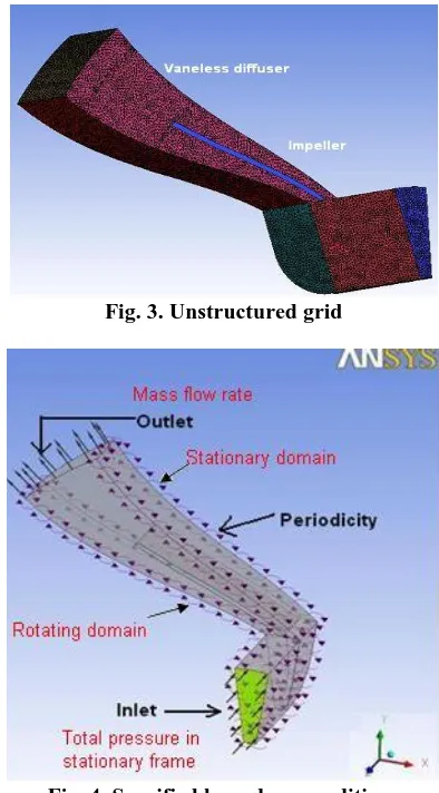
Fig. 3. Unstructured grid
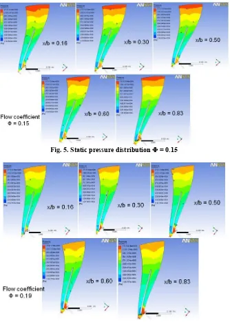
Fig. 4. Specified boundary conditions
[image:2.595.99.242.569.638.2]Therefore, using single passage approach lessens use of computational resources and time. The fluid domain inlet boundary is kept at a distance by about ½ the blade chord length and its outlet part is kept one fourth of the blade chord length. The fluid domain (comprising impeller with blade and vaneless diffuser) modeled is illustrated in Fig. 2. Fluid domain is made of unstructured grid having tetrahedral element. Prism shaped cell are inserted in zones near to the wall as shown in Fig. 3 to obtain a fine resolutions near the boundary layer regions. y plus less than 100 is maintained in the generated mesh to meet the turbulence modeling requirements. As can be seen in Fig. 3, nearly eight prism layers is kept in the regions nearer to wall. Both geometry modeling and meshing are performed with ANSYS ICEM CFD.
Figure 4 highlights the conditions maintained for boundary within the computational domain and it is assigned with rotating frame of reference. Fluid is air at 250C and reference pressure is fixed as 101.325 kPa. Total pressure in stationary frame is mentioned as an inlet condition. The relative total pressure at inlet is zero Pascal. Turbulence model chosen is k-ω SST [17, 18]. Turbulence intensity level is set to 1% (medium level) at inlet. Rotational periodic boundary conditions are assigned for all side walls of the domain. Mass flow rate per passage is assigned as the boundary condition at outlet. Wall boundary conditions are assigned to impeller (viz., blade, hub and shroud) and it rotates at angular velocity as to that of computational domain. Hence, based on relative frame of reference, it is stationary. Suitable interface is specified between diffuser and impeller as the model contains stationary domains (viz., vaneless diffuser) and rotating (viz., impeller). But, vaneless diffuser wall does not rotate in stationary frame of reference. Therefore, it is specified as counter rotating. All walls are enforced with no-slip conditions. Wall roughness is neglected by meaning the wall to be smooth. All numerical investigations are performed with ANSYS CFX. The selection of right turbulence model is results with better predictions on flow separation. k-ω shear stress transport and standard k-ω turbulence models are deployed to obtain the closure for Reynolds Averaged Navier Stokes equations. The obtained values are verified with available experimental results. On comparison with k-ω shear stress transport turbulence (SST) model, k-ω SST model gave numerical values closer to experimental data (refer Table II).
Furthermore investigation is performed using this turbulence model. Based on the grid sensitivity analysis, the unstructured grid generated has a total number of elements at around 788646 elements; including tetrahedral and prism, for the centrifugal stage comprising an impeller and vaneless diffuser (refer Table III). The simulations are performed under steady state and it is computed till root mean square residual values of the computation converged. Residuals convergence criteria are kept as 1x10⁻⁴.
III. RESULTSANDDISCUSSION
Numerical investigations are performed on a compressor stage comprising vaneless diffuser for flow coefficients namely, Ф = 0.15, Ф = 0.19 (design), and Ф = 0.25. A turbo
plane at various axial location represented non-dimensionally as x/b at 0.16 (hub), 0.30, 0.50, 0.60, and 0.83 (shroud). The contours static pressure, total pressure in stationary frame, velocity in stationary frame and meridional velocity are plotted and it is discussed here.
A. Static Pressure Distribution
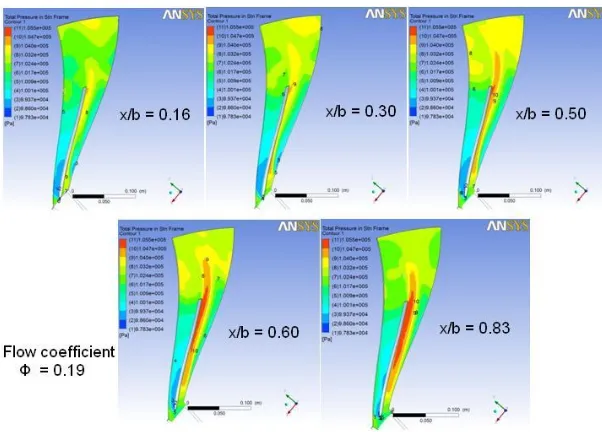
Static pressure increases with radius due to the flow diffusion. This is revealed in the Figs. 5, 6, and 7. As the disks of the impeller are rotating, the particles of fluid stick to the impeller disk and rotate with nearly equal angular velocity. As the distance from disk wall increases, the angular velocity of these fluid particles decreases gradually. Energy is imparted by the impeller onto the fluid result with increase in fluid kinetic energy. This results into static pressure gain as flow progress along the radius ratio. Therefore, as can be seen in Figs 5-7, static pressure observed nearer the wall at x/b = 0.16 and 0.83 is higher in comparison with the mid axial location (x/b = 0.5). This is mainly due to the fact that fluid particles are not gaining any energy addition from these impeller disks. Moreover, the static pressure distribution within the centrifugal impeller is observed to be uniform along blade to blade (viz., circumferential direction) and in the axial direction also namely hub (x/b = 0.16) to shroud (x/b = 0.83). Later, further diffusion occurs in the vaneless diffuser region, where the conversion of kinetic energy of the fluid to static pressure takes place. These are observed with a raise in the static pressure as can be seen in Figs. 5-7. At Ф = 0.19, the maximum rise in static pressure is found. The flow is observed as fully diffused near diffuser exit at Ф = 0.19. On comparison with design flow coefficient, a slight fall in static pressure is observed under off-design flow coefficients. However, static pressure distribution is nearly uniform along shroud to hub and in the circumferential direction..
B. Stagnation Pressure Distribution
Figures 8, 9 and 10 illustrates the stagnation pressure distribution for Ф = 0.15, 0.19 and 0.25 respectively. Again, the total pressure rise with increase in radius ratios. On the other hand, a compressor stage with vaneless diffuser, the total pressure decrease as radius ratio increases. This fall in total pressure is mainly because of friction loss and mixing loss that occurs in the diffuser section. As can be seen in Figures, the distribution pattern of total pressure near the shroud is higher with respect to x/b = 0.50. This trend is observed in all the flow conditions. Also, formation of “jet-wake” is observed at the impeller exit.
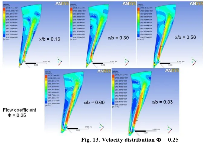
C. Absolute Velocity Distribution
The region of high energy fluid region, viz., the jet and the region with low energy fluid region, viz., the wake is clearly
seen for flow through the centrifugal impeller. This is also clearly seen at impeller exit.
[image:4.595.132.466.84.552.2]Fig. 5. Static pressure distribution Ф = 0.15
Fig. 7. Static pressure distribution Ф = 0.25
Fig. 8. Stagnation pressure distribution Ф = 0.15
[image:5.595.145.446.533.749.2]Fig. 10. Stagnation pressure distribution Ф = 0.25
Fig. 11. Velocity distribution Ф = 0.15
[image:6.595.135.453.298.742.2]Fig. 13. Velocity distribution Ф = 0.25
Fig. 14. Meridional velocity distribution These formations of fluid region with different energy levels
leads to secondary flow along the circumferential region at impeller exit and also lead to mixing of varied energy fluids along the radius ratio leading to loss.
D. Meridional Velocity Distribution
The meridional velocity distributions for is shown in Fig. 14. The meridional velocity initially increases and then decreases gradually along the flow direction as flow occur from entry to exit of vaneless diffuser. The meridional velocity distribution is seen as non-uniform at Ф = 0.15 but, it is uniform at diffuser exit at Ф = 0.25. Moreover, meridional velocity distribution found to be varying between the hubs and should wall of impeller and it is seen to be higher at hub side wall of the impeller.
IV. CONCLUSION
Numerical simulation involving flow through a centrifugal compressor stage with vaneless diffuser is performed for design and off-design flow coefficients. Based on the study, the key observations are mentioned below.
Jet-wake formation is visible as the flow happens through the centrifugal impeller. This trend continues till impeller exit
Fluid region with different energy levels at the impeller exit is observed along the circumferential direction.
Non-uniform flow enters the vaneless diffuser and a considerable mixing happens along the radius ratio leading to losses.
Total pressure and static pressure rise with increase in radius ratio of the stage.
Presence of vortices in the flow field due to the change of flow from axial direction to radial is seen at all flow coefficients.
REFERENCES
1. R. C. Dean Jr, and Y. Senoo, “Rotating wakes in vanless diffusers“, ASME Journal of Basic Engineering, 1960, pp. 563-570.
2. J. R. Johnston, and R. C. Dean, “Losses in vaneless diffuser on centrifugal comrpessor and pumps“, ASME Journal of Engineering for Power, vol. 88, 1966, pp. 49-60.
3. Y. Senoo, and Y. Kinoshita, “Influence of the inlet flow conditions and geometries of centrifugal vaneless diffusers on critical flow angle for reverse flow“, ASME Journal of Fluids Engineering, vol. 99 (1), 1977, pp. 98-102.
4. M. W. Johnson, and J. Moore, “The development of wake flow in a centrifugal compressor“, ASME Journal of Engineering for Power, vol. 102, 1980, pp. 383-390.
5. M. W. Johnson, and J. Moore, “Secondary flow and mixing losses in a centrifugal compressor impeller”, ASME Journal of Engineering for Power, vol. 105, 1983, pp. 24-32.
7. Pinarbasi, and M. W. Johnson, “Off design flow measurement in a centrifugal compressor vaneless diffuser“, ASME Journal of Turbomachinery, vol. 117, 1995, pp. 602-608.
8. Pinarbasi, and M. W. Johnson, “3-D flow measurements in conical and straight wall centrifugal compressor vaneless diffuser“, Journal of Mechanical Engineering Science, vol. 210, 1996, pp. 51-61.
9. Ozturk Tatar, Adnan Ozturk and Ali Pinarbasi, “Flow analysis in centrifugal compressor vaneless diffusers“, Journal of Scientific and Industrial Research, vol. 67, 2008, pp. 348-354.
10. Hariram Venkatesan, John J Godwin, and Seralathan Sivamani, “Data set for extraction and transesterification of bio-oil from Stoechospermum marginatum, a brown marine algae”, Data in Brief, vol. 14, 2017, pp. 623-628.
11. Hariram Venkatesan, Seralathan Sivamani, T. Micha Premkumar, and Penchala Tharun, “Reduction of exhaust emissions using a nano-metallic enriched lemongrass biodiesel blend”, Energy Sources, Part A: Recovery, Utilization and Environmental Effects, vol. 39 (21), 2017, pp. 2065-2071.
12. Hariram, S. Seralathan, M. Dinesh Kumar, S. Vasanthaseelan, and M. Sabareesh, “Analyzing the fatty acid methyl esters profile of palm kernel biodiesel using GC/MS, NMR and FTIR techniques”, Journal of Chemical and Pharmaceutical Sciences, vol. 9 (4), 2016, pp. 3122-3128.
13. Hariram, S. Prakash, S. Seralathan, and T. Micha Premkumar, “Data set on optimized biodiesel production and formulation of emulsified eucalyptus teriticornisis biodiesel for usage in compression ignition engine”, Data in Brief, vol. 20, 2018, pp. 6-13.
14. Hariram, S. Seralathan, R. Vagesh Shangar, and K. Yoga Narasimhulu, “Combustion Characteristics of Waste Pyrolytic Plastic Oil at Full Load Operation in a Direct Injection Compression Ignition Engine”, Journal of Chemical and Pharmaceutical Research, Vol. 7 (5), 2015, Pp. 673-676.
15. Seralathan Sivamani, T. Micha Premkumar, Mohammed Sohail, T. Mohan, and V. Hariram, “Experimental data on load test and performance parameters of a LENZ type vertical axis wind turbine in open environment condition”, Data in Brief, vol. 15, 2017, pp. 1035-1042.
16. T. Micha Premkumar, T. Mohan, and Seralathan Sivamani, “Design and analysis of a permanent magnetic bearing for vertical axis small wind turbine”, Energy procedia, vol. 117, 2017, pp. 291-298.
17. S. Seralathan, and D.G. Roy Chowdhury, “Performance enhancement of a low-pressure ratio centrifugal compressor stage with a rotating vaneless diffuser by impeller disk extended shrouds”, Journal of Applied Fluid Mechanics, vol. 9 (6), 2016, pp. 2933-2947.
18. M. Govardhan, and S. Seralathan, “Effect of forced rotating vaneless diffusers on centrifugal compressor stage”, Journal of Engineering Science and Technology, vol. 6 (5), 2011, pp. 562-578.