Abstract :Agriculture is the most significant industry directly related to human survival. However, the reduction of the labor force according to the continuous decreasing population and aging population brings a decrease in productivity. A smart farm networking system can be an alternative solution to solve these problems. Due to lack of interoperability and scalability, however, many smart farm systems are not sufficiently suitable to be utilized in a real field and a market. This paper proposes a structure of scalable and configurable I/O module interface for the smart farm control system. The proposed smart farm interface makes easy to extend sensor-actuator interface modules which are used for interfacing between sensor-actuator and the main controller, from which the scalability and interoperability can be gained. Also, Sensor data (Digital, Analog) can be easily obtained and the actuator data (PWM, Direction, On/Off) can be controlled regardless of its interface. The interface module can be easily added on the main controller, so additional functionalities to be able to support various sensor and actuator can be easily merged. These advantages are obtained by using local Modbus protocol between the sensor-actuator interface modules and the main controller. The sensor-actuator interface module is designed to divide into two parts; one is the communication parts with the main controller, and the other is the control part for sensors and actuators. With this structure, acquiring data from sensor data and/or sending control data to the actuator can be done independently with the main controller. An operation of sensors and actuators which are connected to the sensor-actuator interface module can be asynchronously done by using shared local registers. From the proposed structure, it is possible to provide configurable interfaces with the scalability using the modular sensor-actuator interface structure under the various environments that are needed to control the smart farm system.
Keywords: Smart Farm, Configurable structure, Sensor interface, Actuator control, Scalable interface, Modbus, IoT interface
I.INTRODUCTION
With the current technological advances, the incorporation of Information and Communications Technology (ICT) is getting more accelerated for the improving productivity and the facilitating management in various industries such as the automobile, factory, health, and city.
Revised Manuscript Received on May 06, 2019
Seong-gyu Lee,Dept. Electronic and Electrical Engineering, Dongguk Univ., 30, Pildong-ro 1-gil, Jung-gu, Seoul, Korea
Anna Yang, Dept. Electronics and Information, Korea Aerospace Univ., 76, Hanggongdaehang- ro, Deogyang- gu, Goyang- si, Kyeonggi-do, Korea2
Byung- Hoon Jeon, Dept. Electronic and Electrical Engineering, Dongguk Univ., 30, Pildong- ro 1-gil, Jung-gu, Seoul, Korea
Hee-dong Park, Dept. of Software Engineering, Joongbu Univ., 305, Dongheon- ro, Deogyang -gu, Goyang-si, Gyeonggi-do, Korea
In agriculture and livestock, advanced technologies such as IoT (Internet of Things), AI (Artificial Intelligence), and big data are developed with convergence. A smart farm system can be used for assisting the growing of crops and of livestock as maintaining an optimal environment. Based on the acquired data from sensors, the smart farm system can maintain an environment being suit to livestock or crops. For example, based on the acquired data from the pre-equipped sensor on the system, it is possible to automatically and remotely
control actuators such as a nutrient solution irrigation system, ventilation fan, chiller/heater, and motor for side windows. Like this, controllability of actuators depending on sensor data makes maintaining certain environment possible. With this, problems which are caused by the shrinking labor force and by the increasing needs to improve the productive capacity can be alleviated.
Under this situation, the smart farm will be the best choice as a solution. The smart farm solution can be used for not only factory farms but also helping cultivation. To become important to develop the smart farm system as a solution for agricultural problems, the development of IoT-based smart farm system is advanced in various areas.
For instances, the IoT based system for ginseng cultivation and recording its history information was designed and is utilized in a real field [1]. An intelligent management system for a fuzzy logic based automated irrigation system in the greenhouse has been studied and developed [2]. Using this, the amount of water absorption would be estimated depending on the irrigation model, the characteristics of the environment of its greenhouse, and the condition of the soil. A greenhouse temperature and humidity control algorithm based on direct Fuzzy logic controller were designed, tested and implemented [3].
And, the study for creating a cultivation environment under the harsh environment has been performed using smart cultivation system [4]. Monitoring has been performed with the measured sensor data from distributed sensors using wireless sensor network [5]. An integrated environmental management system has been designed as building a sensor network for controlling the indoor environment. Actuators are remotely controlled depending on measured sensor data. With this, the greenhouse can be managed without the limits of time and place [6].
A Structure of Scalable and Configurable
Interface for Sensor and Actuator Devices in
Smart Farming System
Using a pressure sensor and a rain sensor, an IoT technology has been applied on the rooftop of the greenhouse for preparing for natural disasters such as heavy rain and heavy snow [7]. IoT based platform that can automate environmental, soil, fertilization and irrigation data collection is proposed [8]. From this study, in order to automatically correlate the data obtained from the platform and to evaluate the performance of the crops, they filtered out the wrong data and calculated the crop forecasts for individual farms and individual crop recommendations.
Not only in agriculture but also in livestock, many studies are underway. To monitor and to manage the swine housing, CCTV and USN sensors which are used for gathering sensor data such as illuminance, humidity, temperature, and ammonia gas, etc. are installed inside and outside of the facility. Using this system, the growing conditions of livestock can be controlled and managed remotely [9]. A system consisting of the physical layer for information gathering and environmental control of livestock farm, application layer that provides the service, and a middle layer that supports communication between physical layer and application layer and maintains best breeding environment through control of device has been proposed and tested for system verification [10].
Although many such studies have been carried out, most of all systems are hard to be standardized because most systems had been designed with no consideration of integration with other devices [11]. Also, systems are developed depending on the characteristics of pre-specified sensors and actuators, which make difficult to use other new or improved devices. If the company who provides the smart farm services decides to stop to support their system anymore, then the customer service also is not available anymore. So, it needs to develop the system with consideration of its scalability and compatibility.
This paper proposes a sensor-actuator interface structure with scalability and compatibility.
II.STRUCTURE OF MODULE INTERFACE
The smart farm system is used for maintaining a certain environment as monitoring and controlling various devices. To support this system, various sensors and actuators are needed. However, in the meantime, already developed sensors and actuators are differently controlled because most interfaces are different. So, it is not easy to integrate them into one system. With this low scalability and compatibility, a data converter which can interface them each other should be needed. The sensor-actuator interface module is proposed as the data converter. The data converter is used for converting from the protocols with different interfaces to one protocol. For instance, the acquisition data from various sensors which provide various signal type such as digital, analog, or network interface will be converted to being fitted with common local bus data. Then, it can easily gather the sensor data using only the common data protocol. Like this, to solve existing problems, the data transmission protocol and the interfaces between sensors/actuators and the main controller can be standardized. However, standardization is not sufficient. This
paper proposes the design of a sensor-actuator interface which is able to easily extend and integrate to the other system. Using this module, manufacturer and system manager provide their system as enabling to independently choose sensors and/or actuators and to install. This will result in establishing an environment in which to choose sensors/actuators to achieve economic feasibility and profitability.
2.1Input-Output Interface
Currently, the standardization of devices for the smart farm is on the advance, but there are still no clear criteria. Therefore, in order to make possible to utilize various sensors/actuators in one system, it is necessary to support various types of input and output interfaces.
The sensor-actuator interface module supports multiple ports for sensor/actuator, and the number of multiple ports is supportable depending on the provided microprocessor by its specification.
The supported sensor input type is digital, analog and other de facto data stream, such as Inter-Integrated Circuit (I2C), Modbus, etc. Especially for analog sensors, the accuracy can be controlled depending on the limitation value of supported voltage and current. Generally, it will be supported above the 12bit Analog-to-digital converter (ADC).
Actuators have to support diverse control methods depending on the specification of the actuator. For examples, irrigation fan or lights are easy to control because it is available to control only using turn-on and turn-off signal. But motors used for a hinged window and/or sunshade are complicated because they need to control the direction and speed of rotation. The rotation direction and speed control could be performed by various methods. And to control the dimming of lights is needed. Therefore, it should support most of the possible control method for various actuators.
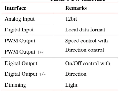
Table 1 I/O interface
Interface Remarks
Analog Input 12bit
Digital Input Local data format
PWM Output Speed control with
PWM Output +/- Direction control
Digital Output On/Off control with
Digital Output +/- Direction
Dimming Light
In table 1 has specified the supported input and control method of output. As an input, digital sensor and analog sensors can be support both, and various control methods also can be supported such as on/off, on/off with direction, PWM (Pulse Width Modulation) for speed control, and PWM with direction. Which involves encoding a control data into a pulsing signal. Its main use is to allow the control of the power supplied to electrical
[image:2.595.303.493.499.645.2]will be controlled by digital output. Especially for the analog sensor, both the current signal and the voltage signal could also be measured.
2.2Connection structure
[image:3.595.56.281.286.449.2]Sensors and actuators which are equipped at the smart farm system can be chosen depending on the optimal environment for crops and livestock. Depending on its necessary condition, a sensor or actuator can be added or deleted. To support this, the scalability should be guaranteed. Figure 1 shows the connection structure of the sensor-actuator interface module with the main controller. The sensor-actuator interface module can communicate the sensor-actuator interface module with the main controller via the local Modbus protocol. The equipped sensors and actuators on the sensor-actuator interface module are configured by using the Modbus protocol. It means that the functionality which the command can be performed by using the pre-defined command in Modbus protocol is supported.
Figure 1 Architecture of Sensor-actuator Interface Module
[image:3.595.307.516.371.636.2]Therefore, the sensor/actuator can be controlled corresponding to predefined functionalities, which guarantees the extensibility for the sensor/actuator addition. With a result, available functionalities can be standardized by using the Modbus protocol. It is usefully used for communicating the sensor-actuator interface module with the main controller. There are many sensor types in the smart farm system, but the following sensor types are supported in the proposed structure.
Table 2 Sensors for the smart farm system Sensor type Remarks
Temperature Indoor and outdoor temperature
Humidity Indoor humidity
CO2 Indoor carbon dioxide
DO Dissolved oxygen of nutrient
solution
EC Electrolysis of a nutrient solution
PH The acidity of nutrient solution
Photo Illumination, intensity
Motion Indoor motion detection
Rain Outdoor weather environment
Wind direction Outdoor weather environment
Wind speed Outdoor weather environment
Load cell Growing bed weight measurement
Sensor types can be added as needed, so the proposed structure has the configurable characteristic which can classify according to the sensor model.
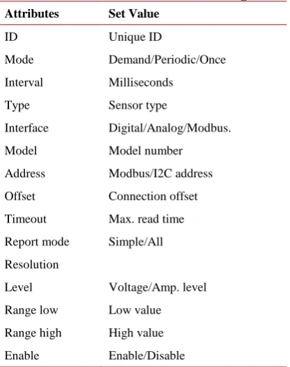
2.3Device attributes
Each sensor or actuator has its own characteristics depending on the type, so each should be determined before connection by a software setting.
The connection and operation of sensor and actuator can be configured using the characteristics shown in table 3, which can be done through the main controller. Therefore, when the sensor type or connection is added, deleted or changed, a dynamic sensor configuration is possible by changing the software setting after the hardware connection.
The characteristic elements related to a sensor are as follows.
Table 3Attributes for sensor configuration Attributes Set Value
ID Unique ID
Mode Demand/Periodic/Once
Interval Milliseconds
Type Sensor type
Interface Digital/Analog/Modbus.
Model Model number
Address Modbus/I2C address
Offset Connection offset
Timeout Max. read time
Report mode Simple/All
Resolution
Level Voltage/Amp. level
Range low Low value
Range high High value
Enable Enable/Disable
III.3.CONTROL SOFTWARE
To ensure the compatibility and scalability of the various sensors and actuators that are installed in the smart farm, the sensor actuator interface module must be able to control the sensors and actuators independently of the main controller. This paper proposes the most useful 'holding register' among various kinds of registers
[image:3.595.47.257.620.787.2]independently from the main controller.
The main controller can control the sensor actuator interface module through an internally determined message. The message between the main controller and the sensor actuator interface module is designed in the form of an abstract message about the type of the sensor and the operation of the actuator, not the command dependent on each sensor or actuator, thereby ensuring compatibility.
In the sensor actuator interface module, the process of the message and the operation process of the sensor and the actuator are designed to be separated.
To be able to do this, holding registers which are the highest usability in Modbus protocol will be used. The holding registers are shared for the message processing and sensor/actuator control.
Messages from the main controller are written to the holding registers and the sensor actuator interface module periodically checks the holding registers. The identified command is processed independently by the sensor actuator interface module and the processing
[image:4.595.316.536.221.577.2]
Figure 2 SW structure of Sensor-actuator Interface Module
result is written to the holding register.
This process allows the sensor actuator interface module to run independently and asynchronously with the main controller, ensuring the scalability and compatibility of each device.
3.1Software structure
Figure 2 shows the software structure of the sensor-actuator interface. It is composed that the message processing part, system configuration part, and I/O controlling part. The message processing part has two main functionalities; one is for communication between the main controller and the Modbus driver, the other is for recording processed data from the message to the holding register.
Holding register addresses are preallocated depending on each action/or command. So, when some command is transmitted to the sensor-actuator interface, that command is updated at the corresponding register. And the command will be performed by checking the value of the corresponding register. The system configuration part is used for setting sensor/actuator information such as storing, setting, and deleting, etc. This is asynchronously performed referred to Modbus holding register. The controlling part is performing the command depending on the set-up information from the
main controller, and also interfacing with sensors and actuators connections.
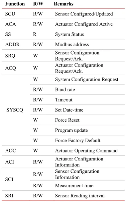
3.2 Functional Register Construction
The command from the main controller is performed via the corresponding holding register in the sensor-actuator interface. One or more action should be referring to one or more holding register field values for performing one specific command. Table 4 shows the construction of holding registers. The function of each holding register is described below, which are not intended for the whole functions but only for the main part.
Table 4 Holding Register components construction Function R/W Remarks
SCU R/W Sensor Configured/Updated
ACA R/W Actuator Configured Active
SS R System Status
ADDR R/W Modbus address
SRQ W Sensor Configuration
Request/Ack.
ACQ W Actuator Configuration
Request/Ack.
SYSCQ
W System Configuration Request
R/W Baud rate
R/W Timeout
R/W Set Date-time
W Force Reset
W Program update
W Force Factory Default
AOC W Actuator Operating Command
ACI R/W Actuator Configuration
Information
SCI
R/W Sensor Configuration
Information
R/W Measurement time
SRI R/W Sensor Reading interval
3.2.1Sensor Configured/Updated
Figure 3 SCU register Configuration
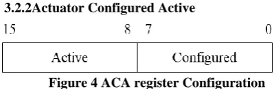
[image:4.595.46.279.309.429.2]3.2.2Actuator Configured Active
Figure 4 ACA register Configuration
As shown in Figure 4, the upper bits of the ACA register indicates whether the actuator is active or not. And, lower bits of the ACA register indicate whether it is configured or not. And, as described above, before doing any actions related to the actuator, it should be checked whether not only the actuator is active or not, but also the actuator is configured or not. This register allows the main controller to check and synchronize the connection and operation of the actuator connected to the sensor actuator interface module.
[image:5.595.313.518.163.222.2]3.2.3System Status
Figure 5 SS register Configuration
System status register indicates the status of the sensor-actuator interface module. Because each module operates independently, the status information of each module must be verified. The status of each module can be checked through the value of this register.
[image:5.595.55.255.244.299.2]3.2.4Sensor Configuration Request/Ack.
Figure 6 SRQ register Configuration
The holding registers for sensor configuration request and acknowledge is defined in Figure 6. To be able to support various sensors, many kinds of sensors should be available to set depending on its type. When to configure their new sensor, the main controller sends a request message to be set-up the sensor. In the message, required sensor information such as model number, sensor number, interface of the sensor, type of sensor, and the reading interval is enclosed. This will be processed in the message processing unit in the sensor-actuator interface. Then, the sensor related required information will be stored in the appropriate holding register. And, this holding register will be referred for acknowledge of the sensor.
3.2.5Actuator Configuration Request/Ack.
Figure 7 ACQ register Configuration
To connect various actuators, the configuration is required depending on its drive type. The main controller can request the setting via the register which is shown in Figure 7. Depending on the location of the port where the actuator is connected, actuator related information can be configured.
Actuator related information is composed of actuator mode, number, type, direction, and polarity.
3.2.6System Configuration Request
Through the system configuration request, the system related setting information of sensor-actuator module interface will be configured. the system related setting information can be composed of a baud rate, timeout, date-time, reset, and program update factory default reset. Using this information, the system will be initialized and configured.
[image:5.595.311.518.320.380.2]3.2.7Actuator Operating Command
Figure 8 AOC register Configuration
As shown in Figure 8, the command for driving motor can be configured. In this holding register, the command value, the direction, and polarity, and the actuator number should be set depending on its specification. With this configuration setting, the actuator which is obtained by the actuator number can be controlled to determine the direction with command value between 0 and 254.
[image:5.595.52.256.379.457.2]3.2.8Actuator Configuration Information
Figure 9 ACI register Configuration
ACI register is configured for storing an actuator. To add a new actuator, ACQ information should be transmitted from the main controller. And, the transmitted information should be composed of actuator type, direction and polarity, and the value. These are referred for driving actuators. If some actuators are activated and the ‘run' command is transmitted, then this holding register should be referred for the confirmation whether this actuator supports the type of transmitted command. Because actuators are controlled in a different way. It is specified in their spec-sheet. And, the supported control type is defined in Table 5.
Table 5 supported actuator type
No Type Interface
1 AC ONOFF Pin1 - ONOFF
2 DC_ONOFF Pin1 - ONOFF
3 DC_ONOFF_DIR
Pin1 - ONOFF Pin2 - Direction Pin1 - CW ON Pin2 - CCW ON
4 DC_PWM Pin1 - PWM
5 DC_PWM_DIR
Pin1 - PWM Pin2 - Direction Pin1 - CW PWM Pin2 - CCW PWM
[image:5.595.305.519.551.725.2] [image:5.595.52.263.632.713.2]Figure 10. SCI register Configuration
SCI register is used for storing sensor configuration information which is equipped sensor information.
Many information should be configured like the sensor type such as temperature, humidity, and CO2, etc., sensor interface such as digital and analog signal, and measuring interval, model type which is used for the combined sensor, Especially, model type is needed for a combined sensor which is capable of many sensors at on device. For example, some of the CO2 sensors are not only supporting the measuring CO2 value, but also the measuring humidity and temperature. In this case, to configure more information is needed for obtaining humidity using a CO2 sensor. First set the model type as CO2, then set the sensor type depending for its various sensors.
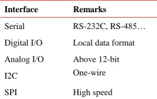
[image:6.595.306.546.72.267.2]The Sensor value field has the value from the sensor and is generally stored as a value with multiple times of values. For example, the temperature value of 34.5 degrees is stored as a number of 345, which is ten times higher, so that the increased precision is supported. Time of Measurement is the time the Sensor value is gathered and is formatted as the number of seconds. In table 6, supported sensor interfaces are shown.
Table 6 Supported sensor interface Interface Remarks
Serial RS-232C, RS-485…
Digital I/O Local data format
Analog I/O Above 12-bit
I2C One-wire
SPI High speed
3.3Software process
This chapter proposes the method of the sensor actuator interface module to operate independently of the main controller.
As mentioned above, each sensor actuator interface module communicates with the main controller using the Modbus protocol, and several interface modules can be connected to the main controller. Each module has a unique ID and receives and processes commands or data transmitted from the main controller.
Figure 11 shows the overall software process. The software of the sensor actuator interface module has a two-step process based on the Modbus holding register to ensure the independence of each module.
The first step is message processing. At this step, the sensor actuator interface module receives command or configuration data from the main controller and writes the data to the corresponding registers. It also reads the updated register
value and sends to the main controller. In this process, sensor or actuator operations are executed, only message processing and register read/write operations are executed.
The second step is the operation processing loop. At this step, the sensor actuator interface module
Figure 11 Software process of Sensor-actuator Interface Module
periodically checks the updated registers through the message processing step and executes the commands. In this processing, each command is executed by referring to only the value of the holding register regardless of the command of the main controller, and the execution result is updated to the holding register.
In this process, messages exchanged between the main controller and the sensor actuator interface module take the form of abstract messages that indicate the device number and action of the sensor or actuator regardless of the data type of device. The sensor actuator interface module converts the abstract message into a command suitable for each device by referring to the pre-set information of the sensor and the actuator. For example, in order to operate the motor, the main controller transmits only the number, direction, and value of the actuator, not the command corresponding to the specification of the actuator. Then, the sensor interface module can generate an output signal corresponding to each device with reference to pre-set information.
In addition, separating the time point of processing the message and the time point of executing the operation of the device by using the holding register, even if multiple sensor actuator interface modules are installed, independence of each operation can be assured. Thus, the scalability of the sensor and the actuator can be secured.
[image:6.595.88.250.462.564.2]3.3.1Sensor Configuration Process
[image:6.595.305.527.591.723.2]Main controller requests the configuring the sensor on the sensor-actuator interface module. When to add or to update sensor information, main controller request sensor configuration by SRQ and the sensor information is stored in the SCI field and the index in the SCU field is enabled. When to delete the sensor, the sensor information is deleted in the SCU field and the index in the SCU field is disabled.
[image:7.595.59.277.144.275.2]3.3.2Actuator Configuration Process
Figure 13 Actuator configuration process
Adding or updating actuator to the sensor-actuator interface can be performed via ACQ field by requesting of the main controller. First, the actuator information is stored at the ACI field. Then, the index of ACA field is enabled. Deleting actuator configuration is performed by deleting date in ACL field and disabling index in the ACA.
[image:7.595.58.280.379.507.2]3.3.3Sensor Data Read Process
Figure 14 Sensor data read process
To read sensor data and write sensor data can be processed as shown in Figure 14. The sensor value will be periodically updated. At that time, the update data status is recorded at the update field in SCU. Thus, as the main controller checks the update field of SCU, updated measured sensor data can be transmitted to the main controller.
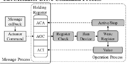
3.3.4Actuator Drive Command Process
Figure 15 Actuator drive command process
The main controller can set the command to drive the actuator via AOC field. After the command is checked, the status of the actuator is confirmed to avoid setting the same
command again. And, ACI field should be checked about the actuator information such as actuator type and output interface. The actuator information can be referred for properly controlling the actuator depending on its characteristics. After then, the changed status of the actuator should be recorded in the ACA field. And, this information is used for synchronizing with the main controller.
IV.CONCLUSIONANDFUTUREWORK
This paper proposes a structure of scalable and configurable sensor-actuator interface for the smart farm control system. The proposed interface structure makes easy to extend sensor-actuator interface modules which are used for interfacing between sensor-actuator and the main controller, from which the scalability and interoperability can be obtained. The interface module is communicated with the main controller by using local Modbus protocols or other interfaces which is a widely used industrial communication protocol. Modbus protocol supports holding register which can be used as user definition. Using the holding register, the configuration, data acquisition, and data writing can be independently and asynchronously performed. The proposed sensor-actuator interface module supports digital and analog sensors, and the user can easily install sensor or actuator devices on their interface module regardless of its connection interface and model type. It also supports various control types as combining operating commands depending on various actuator types.
The proposed sensor-actuator interface module for the smart farm is useful to standardize as a data converter for the smart farm field. Because the standardization is not enough stage to utilize in a real field. Many companies make their own system using self-standard. It causes a lack of compatibility. So, if minimum functions for them are provided, then the smart farm systems which are made by other companies can have the compatibility. And, also the other companies can reduce the development period to the market. Moreover, this proposed module can be used in the livestock industry and the aquaculture industry. The sensor-actuator interface module will be developed and improved through future works.
REFERENCES
1. Moon Taekwhan, Kim Gunwoo, Kim Hyunsung, Oh Jungeun, Lim Jeayun, Kim Dongjin, Choi Kyungwha, IoTBased GinsengSprouts SmartfarmSystem, Proceedings of Symposium of the Korean Institute of communications and Information Sciences, 2017.6, 1133-1134 2. Guerbaoui, M., A. Ed-dahhak, Y. EIAfou, A. Lachhab, L. Belkoura, and
B. Bouchikhi, Implementation of direct fuzzy controller in greenhouse based on labview, International journal of electrical and electronics engineering studies. (2013), Vol.1, No.1, pp1-13.
3. M. GUERBAOUI, and A. ED-DAHHAK, and Y. EL AFOU, and A. LACHHAB, and L. BELKOURA, and BENACHIR BOUCHIKHI, (2013) Implementation of Direct Fuzzy Controller In Greenhouse Based on Labview,. International journal of Electronics Engineering Studies (IJEEES), Vol. 1, Issue 1, September 2013, pp 1-13.
[image:7.595.51.267.610.720.2]5. Prabhu, S.R.Boselin, Environmental Monitoring and Greenhouse Control by Distributed Sensor Network (November 26, 2016). Int. J. Advanced Networking and Applications, Volume: 5 Issue: 5 Pages: 2060-2065, 2016
6. Lee, M.H., C.S. Shin Y.Y. Jo, and H. Yoe, Integrated management system of a greenhouse environment in ubiquitous agriculture. Journal of communications of the Korea information science society, (2009), Vol.27, No.6, pp21-26.
7. Kim, S.Y., H.H. Kim, and H. Yoe., Design of IoT sensorbased greenhouse skylights control system, 2014 Autumn Conference of the Korean institute of communications and information sciences, p. 176-177, KAIST, Korea.
8. Prem Prakash Jayaraman, Ali Yavari, Dimitrios Georgakopoulos, Ahsan Morshed, Arkady Zaslavsky, Internet of Things Platform for Smart Farming: Experiences and Lessons Learnt, Sensors 2016, 16(11), 1884 9. Jeong-hwan Hwang, Meong-hun Lee, Hui-dong Ju, Ho-chul Lee,
Hyun-joong Kang, Hyun Yoe, Implementation of Swinery Integrated Management System in Ubiquitous Agricultural Environments, The Journal of The Korean Institute of Communication Sciences 35(2), 2010.2, 252-262
10. Hwang Jeong hwan, Yoe Hyun., A Study on the Ubiquitous Livestock Farm Management System Based Wireless Sensor Networks Using Smart Phone. The Journal of Korean Institute of Communications and Information Sciences, 2011, 91-92.
11. Korea Rural Economic Institute (KREI), Strategies and tasks of ICT convergence for the creative agriculture realization. (2014), pp.85-104. 12. Anna Yang, Jae-Gon Kim, Bo-Hyun Cho, Hee-Dong Park., An architecture and Design of Data Converter for IoT-Based Smart Farm. International Journal of Smart Home Vol. 12, No. 4 (2018), pp.7-12 13. Seong-gyu Lee, Bo-hyun Cho, Hee-dong Park., Design of Scalable
Sensor and Actuator Interface Module for Smart Farm. International Journal of Smart Home Vol. 12, No. 4 (2018), pp.1-6
AUTHORS PROFILE
Seong-Gyu, Lee received the B.S and M.S. degree from University of Seoul, Korea, in 2013. He is currently working toward the Ph.D. degree in the Department of Electronics and Information Engineering, Dongguk University, Korea. He is now working for the development of a smart farm in global smart solution Inc. His current research interests include Internet of Things, smart farm/factory.
Email:[email protected]
Anna Yang, received the MS. degree from Korea Aerospace University, Korea, in 2017. She is currently working toward the Ph.D. degree in the Department of Electronics and Information Engineering, Korea Aerospace University, Goyang-city, Korea. Her current research interests include IoT/wearable media applications, and MPEG standards.
Email:[email protected]
Byung-Hoon, Jeon, He received B.S and M.S degree in Electrical Engineering from Dongguk University, Korea, in 1992 and 1994, and the Ph.D. degree in Electronics engineering from Keio University, Japan, in 1999. He is now a professor in Department of Electrical Engineering, Dongguk University.
Email: [email protected]
Hee-Dong Park, He received BS degree in Electronics from Kyungpook National University, in 1982, M.S. degree in Computer Engineering from Pohang Institute of Science and Technology (POSTECH), and Ph.D. degree in Computer Science from Gyeongsang National University. He was a research staff in Electronics and Telecommunications Research Institute (ETRI). He is now a professor in Department of software Engineering, Joongbu University. His research interests include Internet of
Things, computer network, parallel and distributed computing, embedded systems, and system software.