Abstract: Microstrip Patch Antenna is a compact low profile antenna which can be embed on the surface. This paper explains various feeding techniques applicable for rectangular microstrip antenna for 3.4 to 3.6 GHz for WiMax applications. Based on contact and non-contact techniques various feeding methods are discussed here. RF power is feed directly to the patch using conducting element for contact feed where as in non-contact feed the power is feed to the patch and the microstrip line through electromagnetic coupling. The simulation results shows the comparative study of various performance metrics such as Return Loss, Radiation Pattern in 2D and 3D, VSWR, Field Directivity, Total Power Efficiency, Current Distribution and Total Field gain using IE3D EM software.
Keywords :Antenna Efficiency, Directivity, Microstrip Patch Antenna, Feeding Techniques, Return Loss, Radiation Pattern.
I. INTRODUCTION
I
n wireless communication, antenna is one of the primary components. It is used as transceiver for the RF waves over a different frequency ranges. Based on the technology and direction of radiation pattern the antenna can be categorized as so wired and wireless antenna also omni directional, directional and semi-directional antenna respectively. Microstrip Patch Antenna (MSA) plays main role in Wireless Communication. Now days in aircraft, space communications, military applications there is a demand of low profile, low cost, compact broadband antenna are required for communicating data between two ends [1]. MSA are classified as microstrip patch antenna, printed antenna, printed slot antenna and travelling wave antenna. Patch antenna is the basic type of microstrip antenna. In Microstrip Patch Antenna (MSPA), the dielectric substrate is between radiating patch and the ground plane. Patches are available in numerous shapes such as circular, triangular, rectangular and ring etc. The author in [4] proposed the rectangular microstrip patch antenna operate in different frequency bands. Compared to conventional antenna MSPA have more advantages in terms of cost and structure [3]. Many researchers are addressed to design MSPA with improvedRevised Manuscript Received on November 17, 2019.
* Correspondence Author
Dr.T.Blesslin Sheeba, Professor, Department of ECE in R.M.K. Engineering College, Mail: [email protected]
T. V. Padmavathy, Professor, Department of ECE in R.M.K. Engineering College, Mail: [email protected]
D.S. Bhargava, Assistant professor in ECE in R.M.K Engineering College, Mail: [email protected]
S.Jagadeesh Babu, Assistant Professor, Department of ECE in R.M.K. Engineering College, Mail: [email protected]
performance in terms of gain, bandwidth and power [2], [5] and [6].
II. RELATED WORKS
In this section the antenna performance metrics are discussed in terms of design techniques, feeding methods and topologies. Microstrip patch antenna finds wide applications compared to conventional antenna due its flexibility, bandwidth and cost [7]-[9]. The single element edge feed rectangular microstrip patch antenna was discussed in [11]. Here the patch dimensions are calculated based on transmission model equation. The impedance of microstrip line and quarter wave length transformer are not mentioned in their work. The designed antenna was simulated using Sonnet tool. Photonic antenna with pin diode was proposed in [10]. In this PIN diode convert the optical signal to RF signal for radiation. The patch was radiated by 50 ohm transmission line. In this the design equations not mentioned. High gain RMSPA with four element antenna was proposed in [12] and [13]. The fabricated antenna provided less antenna efficiency and poor return loss. These types of antenna not suitable for medical applications. Defective ground structure antenna was presented in [14]. The antenna quoted in [14] had some advantages with respect to size of patch, gain and bandwidth.
III. ANTENNA GEOMETRY
Microstrip Patch Antenna contains a conducting rectangular patch of width W and length
L
thickness of dielectric substrate ish
and having dielectric constant
r. Usually to get wider bandwidth, the width W of Patch is larger than lengthL
. The length of the patch should be slightly less thanhalf wavelength
2
to operate the antenna in the transverse
magnetic field dominant
TM
10
mode, where 𝝀 in thedielectric medium.To design a microstrip patch antenna some parameters are to be calculated such as length and width of the patch. Here the proposed antenna has minimum targeted frequency is 3.6 GHz. A suitable dielectric substrate should be choosing with a thickness
h
. A resistant substrate with a dielectric constant
r of 4.4, dielectric loss tangent
tan of 0.002 and substrate height h of 1.6mm.
Design of Feeding Techniques for Slotted
Rectangular Microstrip Patch Antenna
(RSMA)
A. Design Equations of Patch Antenna
Antenna’s resonant frequency can be controlled by the length of patch. The following equation shows the relation between physical length and the resonant frequency. The patch length can be found from,
L eff r
f
C
L
2
2
(1)The variation in length
L
andh
are negligible up to frequency 2GHz.Because of fringing electrically theL
is extended to
L
. Extension length is the additional length required due to the fringing field and it can be calculated using equation (2),)
8
.
0
/
)(
258
.
0
(
)
264
.
0
/
)(
3
.
0
(
412
.
0
h
W
h
W
h
eff effL (2)
Antenna dimensions and the height of the substrate decide the fringing effect. The electromagnetic waves travels in both substrate as well as in air. Therefore, in order to include this effect we have to find this effective dielectric index. This can be written as,
2 1 12 1 2 1 2 1 W h r r eff
(3)
Where h=height of the substrate
The actual length of the patch is
L eff L
L 2
(4)
The radiating patch width is
1 2
2
r r
f C
W (5)
Where C = 3 x
10
8m/s (free space velocity)r
f
= Resonant frequencyr
= Dielectric constant of the substrateThe length and width of the substrate can be obtained from
h
W
W
h
L
L
P s P s6
6
(6)Feed point location can be calculated from equation (7) and (8)
Along X direction from
L
Piseff P
L
X
2
(7)Along Y direction from
W
Piseff P
W
Y
3
(8)B. Proposed Geometric Structure
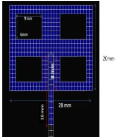
Fig.1 shows the proposed geometric structure of antenna consists of four slotted rectangular patch with a dimension of
L
W
and is fed using an inset planar feed. The structure of a rectangular patch antenna has Width, 28mm
W LengthL20mm and Dielectric constant=4.4.
IV. FEEDING TECHNIQUES
Feed lines are used to radiate energy Basically there are four types of feeding techniques are used in microstrip patch antenna they are edge feed, inset feed, coaxial feed and proximity feed. Since antenna is radiating from single side of substrate it is easy to feed it from ground plane. While designing an antenna one of important factor is impedance matching. The maximum power will be transferred only if there is impedance matching between feed line and input impedance of the antenna. If there is mismatching of impedance then the overall efficiency of antenna is reduced. A. Edge Feed or Microstrip Feed
Here the patch is excited through microstrip line. In edge feeding the feed is etched from the substrate so the structure is planar. The drawback of this type of feeding method is radiation from the feed line intensifies the cross polarization. Since the feed line size is smaller than size of the patch which leads the undesired radiation in the Millimeter wave range. Fig. 2 (a) and (b) shows the geometry structure and equivalent circuit of microstrip patch antenna with edge feed for the frequency 3.6GHz.
B. Probe Feed or Coaxial Feed
The probe feed is also known as coaxial feed. In coaxial feed there are two conductors. The internal coaxial cable is soldered to the radiating element where as the external coaxial conductor is attached to
the ground plane. The equivalent electrical network is
Patch Antenna
L1
[image:2.595.372.492.60.201.2]R L2
Fig. 1 Proposed Geometric Structure
[image:2.595.45.288.309.679.2] [image:2.595.305.563.541.654.2]shown in figure. The patch is located at (0, 0) and the probe is fed at (2,0), (3,0), (4,0), (5,0), and (6,0).The advantage of this type of feeding is, the position of the inner cable is adjusted in a desired direction in order to match the input impedance of the antenna. But this technique leads the impedance mismatch due to substrate thickness. If the substrate thickness increases the enlarged the probe length and makes the input impedance more inductive which causes the mismatch impedance.
C. Proximity Feed
Proximity feed is also known as electromagnetic coupling feed. This feeding technique uses two dielectric substrate. Feed line is attached between the two substrate and patch is placed on the upper substrate. The structure of antenna has of a rectangular patch with quad slot as a radiating patch, dimension of W × L and is excited using proximity feed. The structure consists of a rectangular patch antenna. Width (w) = 28mm, Length (L)= 20mm and Dielectric constant=4.4.The benefit of this type of feeding is it eliminated the undesired radiation and gives higher bandwidth. But this technique has some cons that is the fabrication of antenna is more complex as well as the cost is high. This type of feeding technique gives high antenna efficiency and radiation efficiency only if both the dielectric is aligned properly.
V. SIMULATION RESULTS A. Efficiency of Antenna
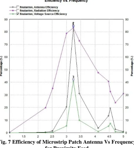
The following Fig.5, 6 and 7 shows the radiation efficiency, antenna efficiency vs frequency and voltage source efficiency for edge feed, probe feed and . As the frequency increases the radiation efficiency of the antenna get decreases. Here the antenna efficiency is 78.28%, voltage
[image:3.595.317.553.128.300.2]source efficiency is 32.77% and radiation efficiency is 81.99% for edge feed, antenna efficiency is 44.79%, voltage source efficiency is 18.13% and radiation efficiency is 78.46% for probe feed and antenna efficiency is 82.478% , voltage source efficiency is 40.52% and radiation efficiency is 83.08% for proximity feed
[image:3.595.37.178.163.301.2]Fig. 5 Efficiency of Microstrip Patch Antenna Vs Frequency for Edge Feed
Fig. 6 Efficiency of Microstrip Patch Antenna Vs Frequency for Probe Feed
Fig. 7 Efficiency of Microstrip Patch Antenna Vs Frequency for Proximity Feed
Patch
Antenna R L1
C1
C2
Patch Antenna
R L2
C L1
Fig. 4 (a)Geometric Structure of Proximity Feed (b) Equivalent Circuit
[image:3.595.307.549.338.455.2] [image:3.595.313.541.503.755.2] [image:3.595.42.295.537.646.2]B. Directivity
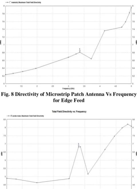
[image:4.595.48.288.217.547.2]The total field directivity of 3.6GHz Microstrip patch with various feeding techniques are shown in Fig.8,9 and 10. The maximum directivity of the antenna is indicating the direction of theta. The two and three dimensional diagram shows the total directivity of antenna with respect to edge, probe and proximity feed. At low frequency that is below the operating frequency as the value of theta increases the value of directivity is decreased. On other hand when antenna operating high frequencies the directivity is almost constant but when it is in 30 degree, the proximity feed provides high directivity compared to edge and probe feed.
[image:4.595.308.556.223.842.2]Fig. 8 Directivity of Microstrip Patch Antenna Vs Frequency for Edge Feed
Fig. 9 Directivity of Microstrip Patch Antenna Vs Frequency for Probe Feed
Fig. 10 Directivity of Microstrip Patch Antenna Vs Frequency for Proximity Feed
C. Return Loss
This is the one of the main parameter which is used to measure reflected power from the antenna due to mismatch of impedance. If the reflected power and input power are equal then return loss of the antenna is 0dB.The antenna is said to be an efficient only if the return loss is very low. The plot 11, 12 and 13 shows that -12.2dB, -4.13dB and -35.5dB for edge feed, probe feed and proximity feed respectively at the operating frequency 3.6GHz.
[image:4.595.312.554.247.518.2]From the graph we infer that high return loss indicates maximum input power is entering into the antenna which means that only minimum power is reflected back from the antenna. So the simulation results show that proximity feeding technique radiates more power compared to edge and probe feed.
Fig. 11Return Lossof Microstrip Patch Antenna Vs Frequency for Edge Feed
Fig. 12Return Loss of Microstrip Patch Antenna Vs Frequency for Probe Feed
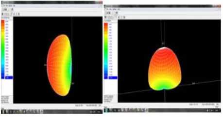
[image:4.595.49.286.600.762.2]D. Radiation Pattern
Radiation pattern is the picturesque illustrating the properties of antenna. This three dimensional graph shows the direction of radiation intensity. The Red colour shows the direction of maximum radiation which indicates the main lobe. The following Fig. 14,15 and 16 shows the radiation pattern with respect to directivity and gain of the proposed antenna for edge feed, probe and proximity feed.
E. Current Distribution
[image:5.595.304.549.51.216.2]The proposed antenna is used for defense, Medical and communication applications. The operating frequency is varying from 3.6GHz to 3.9GHz. The dielectric material used here is FR4 which as dielectric constant 4.4. Here we compared three different feeding techniques. The proposed antenna is simulated using IE3D EM simulation tool. Fig.17, 18 and 19 shows the current distribution for edge feed, probe feed and proximity feed.
[image:5.595.302.548.63.366.2]Fig. 17 Current Distribution of Microstrip Patch Antenna with Edge Feed
[image:5.595.59.284.175.304.2]Fig. 18 Current Distribution of Microstrip Patch Antenna with Probe Feed
Fig. 19 Current Distribution of Microstrip Patch Antenna with Proximity Feed
F. Analysis of Feeding Techniques
The Table 1 shows the performance metrics of different feeding techniques
Table 1 Analysis of Feeding Techniques Parameters
Edge Feed
Probe Feed
Proximity Feed Antenna
Efficiency 78.28% 44.79% 82.47% Radiation
[image:5.595.302.549.433.624.2] [image:5.595.54.284.494.615.2]Voltage Source
Efficiency 32.77% 18.13% 40.52% Directivity 6.86dB 6.84dB 6.94dB
Gain 5.47dB 3.11dB 6.12dB
Return Loss -12.2dB -4.13dB -35.5dB VI. CONCLUSION
In this paper, a relative study between feeding techniques for a RSMA is done. The edge feeding, probe feed and proximity coupled feeding are compared on the basis of various parameters such as antenna efficiency, radiation efficiency, voltage source efficiency, Directivity, Reflection Gain, S11 parameter and Radiation Pattern. The simulation is carried out using IE3D EM simulation tool. Based on simulation result the proximity feed provides better results compared to edge and probe feed. The Proximity feed provides low return loss and high gain for the dielectric material which as dielectric constant 4.4 at an operating frequency of 3.6GHz. Also proximity feed gives good impedance matching between feed line and antenna impedance therefore this type of feeding provides good communication between transmitter and receiver that is it provides less reflection between source and destination. Thus the Proximity Coupled feed is more useful for the X-Band applications.
REFERENCES
1. Gary, R., Bhartia, P., Bahl, I. & Ittipboon, A. (2001).Microstrip Antenna Design Handbook. Boston: Artech HouseInc., pp. 1 - 812.
2. Ogunlade Michael Adegoke, Charles Okand aNyatega,,Design Of Dual Band Coax Patch Antenna For GSM and Bluetooth Application, International journal of science and research,3(12),998-1002,2012. 3. Sourabh Bisht, Shweta Saini, Dr Ved Prakash, Bhaskar Nautiyal, Study
The Various Feeding Techniques of Microstrip Antenna Using Design and Simulation Using CST Microwave Studio, International Journal of Emerging Technology and Advanced Engineering, 4(9), 318-324, 2014. 4. Sanjay R. Bhongale, Pramod N. Vasambeka,Comparison of Stripline and
Coaxial Feeding In Rectangular Microstrip Patch Antenna, International Journal of Electronics Communication and Computer Technology,5,21-24,2015.
5. Balanis, C. A. (2005). Antenna Theory: Anaysis and Design.3rd ed. New Jersey: John Wiley and Sons, Inc. pp. 1 - 144,811 - 876
6. ]K. Praveen Kumar, K. Sanjeeva Rao, T. Sumanth, N. Mohana Rao, R. Anil Kumar, Y.Harish,(2013) Effect of Feeding Techniques on the Radiation Characteristics of Patch Antenna: Design and Analysis International Journal of Advanced Research in Computer and Communication Engineering Vol. 2, Issue 2.
7. Khraisat, Y. S. (2012). Design of 4 Elements RectangularMicrostrip Patch Antenna with High Gain for 2.4GHzApplications. Modern Applied Science, 6(1): 68 – 74.
8. Hemant Kumar Varshney, Mukesh Kumar, A.K.Jaiswal, Rohini Saxena and Anil Kumar (2014) Design Characterization of Rectangular Microstrip Patch Antenna for Wi-Fi Application, Vol.4, No.2, E-ISSN 2277 – 4106, P-ISSN 2347 – 5161.
9. D. Sanchez-Hernandez and I. D. Robertson, “A Survey of Broadband Microstrip Patch Antennas,” Microwave Journal, pp. 60-84, sept 1996. 10.Dipak K. Neog, Shyam S. Pattnaik, Dhruba. C. Panda, SwapnaDevi,
BonomaliKhuntia, and Malaya Dutta, “Design of a Wideband Microstrip Antenna and the Use of Artificial NeuralNetworks in Parameter Calculation”, IEEE Antenna and Propagation Magzine, vol. 47, No. 3, pp. 60-65, june 2005
11.Martin, M. A., & Sayeed, A. I. (2011). A Design Rule for Inset-fed Rectangular Microstrip Patch Antenna. WSEAS Transaction on Communication, 1(9), 63 - 72.
12.Buttar, T. S., & Sharma, N. (2014). Design of Rectangular Microstrip Antenna for Wireless Communication. International Journal of Modern Sciences and Engineering Technology (IJMSET), 1(6), 47 - 52. 13.Khraisat, Y. S. (2012). Design of 4 Elements Rectangular Microstrip Patch
Antenna with High Gain for 2.4GHz Applications. Modern Applied Science, 6(1): 68 - 74.
14. Prakash Kuravatti, “ Comparison of Different Parameters of the Edge Feed and the Inset Feed Patch Antenna”, International Journal of Applied Engineering Research, Vol.13,No. 13, pp. 11285-11288, 2018.
AUTHORSPROFILE
Dr.T.Blesslin Sheeba received her Ph.D in Crytptographic Algorithms for Small Embedded Applications from Sathyabama University, Chennai. She is working as Professor in the department of ECE, RMK Engineering College, Chennai. She has 26 years of Teaching and research experience. She has published more than 25 research papers in International and National Journals. Her current area of research includes security and architecture issues in networks and Antenna design. She is recognized as Fellowship member by The Institution of Engineers (India) also she is a member of various professional bodies such as Life member of Indian Society for Technical Education ISTE, IACST, ACM and ISSE.
T. V. Padmavathy Professor, Department of ECE in R.M.K. Engineering College, has 24 years of teaching and research experience in the in the fields of Wireless sensor networks, Under Water Acoustic Sensor Networks and Antenna Design. She has graduated from Institution of Engineers (India), in Electronics and Communication Engineering. She has obtained her Master degree in Control and Instrumentation from College of Engineering, Guindy, Anna University, Chennai and Ph.D. degree from Anna University, Chennai. She has published more than 50 research papers in International and National Journals and conferences in the area of Mobile Ad hoc Networks, Wireless sensor networks, Under Water Acoustic Sensor Networks and Antenna design and she has four Patents in Wireless Sensor Networks. Her current area of research includes security and architecture issues of Mobile ad hoc networks, Wireless sensor networks and Millimeter Wave Antenna design for Wireless Communications. She is a technical paper reviewer for African Journal of Engineering Research and Journal of Engineering and Technology Management. She is recognized as Fellowship member by The Institution of Engineers (India) also she is a member of various professional bodies such as Institute of Electrical and Electronics Engineers (IEEE), Life member of Institution of Electronics and Telecommunication Engineers (IETE), International Association of Engineers (IAENG), ACM, ISSE and Life member of Indian Society for Technical Education ISTE.
D.S. Bhargava Assistant professor in Electronics and Communication Engineering department of R.M.K Engineering College, has 5 years of teaching experience. He received his Bachelor’s degree from J.N.N Institute of Engineering in Electronics and Communication Engineering in the year 2012 and Master’s degree in VLSI Design from R.M.K Engineering College in the year 2014. His area of interests includes Cognitive radio networks and VLSI Design technology. He has published 7 research papers in International and National Journals and conferences in the area of VLSI Design, Networking and Cognitive radio networks. He is a Life member of ISTE.