WASTE LEVEL SENSOR
NUR SY AZWANI BINTI SALIHON
This Report Is Submitted In Partial Fulfillment of Requirements for the Bachelor of Electronic Engineering (Telecommunications Electronics)
Faculty of Electronic and Computer Engineering
Universiti Teknikal Malaysia Melaka
April20ll
UNIVERSTI TEKNIKAL MALAYSIA MELAKA
FAK.ULTI KEJURUTERAAN ELEKTRONIK DAN KEJURUTERAAN KOMPUTER
BORANGPENGESAHANSTATUSLAPORAN
PROJEK SARJANA MUDA ll
Tajuk Projek Waste Level Sensor
Sesi Pengaj ian 2010/2011
Saya NUR SY AZWANI BINTI SALIHON mengaku membenarkan Laporan Projek Sarjana Muda ini disimpan di Perpustakaan dengan syarat-syarat kegunaan seperti berikut:
I. Laporan adalah hakmilik Universiti Teknikal Malaysia Melaka.
2. Perpustakaan dibenarkan membuat salinan untuk tujuan pengajian sahaja.
3. Perpustakaan dibenarkan membuat salinan laporan ini sebagai bahan pertukaran antara institusi pengajian tinggi. 4. Sila tandakan ( '</ ) :
D
SULIT*D
TERHAD*[I]
TIDAK TERHAD(TANDATANGAN PENULIS) Alamat Tetap:
(Mengandungi maklumat yang berdarjah keselamatan atau kepentingan Malaysia seperti yang termak'tub di dalam AKT A RAHSIA RASMI 1972)
(Mengandungi maklumat terhad yang telah ditentukan oleh organisasi/badan di mana penyelidikan dijalankan)
Disahkan oleh:
(COP DAN T ANDA T ANGAN PENYELIA) ENCa.~UIIOIIIAJI'
Peu,anft No 39, Jalan Bendahara 2!2, Taman Bendahara, 45000
Kuala Selangor, Selangor
111
"I hereby declare that this report is the result of my own work except for quotes as
cited in the references."
Signature
Author
Date
:
.
...
~
...
.
: NUR SY AZW ANI BINTI SALIHON
: 30 APRIL 2011
iv
"I hereby declare that I have read this report and in my opinion this report is
sufficient in terms of the scope and quality for the award of Bachelor of Electronic
Engineering (Computer Engineering) With Honors."
Signature
Supervisor's Name
Date
: Engr. Khairuddin Bin Osman
J--
j
'
d
;>-e I 1v
Dedicated to my family, specially to my beloved mother, father, brother and sisters,
my lecturers and lastly my friends
vi
ACKNOWLEDGEMENT
Alhamdulillah, thank to Allah S.W.T because of his blessing and truth, I
finally finish my final year project successfully. In completed this project, I was met
with many people that help me a lot until I successfully write this thesis. There are
many problems occur during my project work. But this not a big matter cause I have
many reference from my senior and other lecturer from my faculty.
First and foremost, I would like to express my heartily gratitude to my
supervisor, Engr. Khairuddin Bin Osman for the guidance given throughout the
progress of this project.
My appreciation also goes to my family who has been so tolerant and
supports me all these years. Thanks for their guidance, encouragement, advice and
emotional supports that they had given to me along my way to prepare this project
Finally, my project would not be carried out smoothly without the continuing
support and encouragement given by my lecturers, and my friends. I would like to
express my sincere gratitude to them especially for their helping during the time in
Vll
ABSTRACT
This project details the process used to develop the waste level sensor. In
particular waste level sensor was using the PING ultrasonic distance sensor to sense the level of the waste. As sensor detected the waste level from the top of the tank, the data will be transmitted to the Visual Basic through the PIC 16F877 A
microcontroller.
The aims of this project are to measure industrial waste level and convert it to digital signal and model the waste level by using microcontroller to measure the waste level. The aim was also to measure industrial waste level by using Liquid Crystal Display. The measurement will be transmit and receive distant level signal by using The Ping ultrasonic distance sensor.
Other than that, this water level sensor also can be applied in industry where
the chemical liquid in the tank can be measured. So that if the chemical liquid is
going to overflow, the Visual Basic will display the status of the waste level thus the quality of the environment can be improved immediately.
The Waste Level Sensor consists of a hardware platform that is controlled by
a microcontroller. The prototype developed for this project is functional and the results of all the testing undertaken have been successful.
viii
ABSTRAK
Projek ini rnenceritakan rnengenai sesuatu proses yang digunakan untuk
rnenghasilkan pengesan paras buangan bahan kirnia. Pengesan yang digunakan
dalarn projek ini adalah jenis Sensor Jarak Ultrasonik PING yang akan rnengesan
paras buangan bahan kirnia. Apabila sensor rnengesan paras buangan bahan kirnia
tersebut dari atas tangki, data akan dihantar ke Visual Basic rnelalui rnikropengawal
PIC16F877 A.
Matlarnat projek ini adalah untuk rnengukur paras buangan bahan kirnia dan
rnenukarkannya dalarn isyarat digital dan rnernodelkan paras sarnpah dengan
rnenggunakan mikrokontroller untuk rnengukur tahap buangan bahan kirnia.
Matlarnat projek ini juga adalah untuk rnengukur tahap buangan bahan kirnia industri
rnenggunakan paparan kristal cecair yang mana pengukuran akan dihantar dan
rnenerirna isyarat tahap jauh menggunakan Sensor Jarak Ultrasonik PING.
Selain daripada itu, pengesan paras buangan bahan kimia ini juga boleh
diaplikasikan dalarn industri dirnana cecair kirnia di dalarn sesebuah tangki dapat
diukur. Jadi apabila cecair kirnia ini rnencapai aras lirnpahan air, Visual Basic akan
rnernaparkan status paras buangan bahan kimia, dengan itu kualiti alarn sekitar akan
tetjamin.
Tangki pengesan paras buangan bahan kirnia ini rnengandungi perkakasan
yang dikawal oleh rnikropengawal. Prototaip bagi projek ini telah berfungsi dan hasil
TABLE OF CONTENTS
CHAPTER TITLE
I
n
PROJECT TITLE
REPORT STATUS VERIFICATION FORM
STUDENT'S DECLARATION
SUPERVISOR'S DECLARATION
DEDICATION
ACKNOWLEDGEMENT
ABSTRACT
ABSTRAK
TABLE OF CONTENTS
LIST OF FIGURES
LIST OF TABLE
INTRODUCTION
1.1 Overview
1.2 Project Objective
1.3 Problem Statement
1.4 Project Scope
1.5 Methodology
1.6 Thesis Outline
LITERATURE REVIEW
2.1 Components Used in Waste Level Sensor 2.1.1 Microcontroller PIC16F877 A
©
Universltl Teknikal Malaysia Melaka2.1.2 Ultrasonic Sensor
2.2 Types of Sensor
2.3
2.2.1 The PING Ultrasonic Distance Sensor
Literature Review of the Waste Level Sensor
2.3.1 Sonar Made Simple
III
RESEARCH METHODOLOGY
3.1 Methodology
3.2 Literature Review
3.2.1 Selecting Microcontroller
3.2.1.1 Microcontroller PIC 16F877 A
3.2.1.2 Datasheet of PIC 16877 A
3.2.1.3 Connection to PIC16F877A
3.2.2 RS232 to TTL
3.2.3 Visual Basic Programming
IV
RESULT AND ANALYSIS
4.1 Preliminary Result
4.1.1
An
Ultrasonic Sensor4.1.2 Microcontroller PIC 16F877 A
4.1.3 RS232 to TTL
4.2 Expected Result
4.2.1 Project development
4.3 Project Analysis
4.4 Discussion
V
CONCLUSION AND RECOMMENDATION
5.1
Conclusion5.2 Recommendation
REFERENCES
APPENDIX A APPENDIXB APPENDIXC APPENDIXD
©
Universlti Teknikal Malaysia MelakaXI
53
54
56
58
65
Xll
LIST OF FIGURES
NO TITLE PAGE
1.1 Methodology of the project. 4
2.1 Pin Diagram ofPIC 16F877A. 9
2.1 Ultrasonic Sensor. 10
2.2 The PING Distance Ultrasonic Distance Sensor. 12
2.3 The Dimension of the Sensor. 13
2.4 The Devantech SRF04 Sonar Range Finder Sensor and the
IntelliBrain robotic controller. 14
2.5 Sonar Ping and Echo. 15
2.6 Devantech SRF04 Signals. 16
2.7 Devantech SRF04 Connection. 17
2.9 Range Sensor Connection. 17
2.8 Connections to the IntelliBrain Controller. 18
3.1 Methodology of the Project. 21
3.2 PIC 16F877 A. 23
3.3 Connection of Oscillator with Pin 13 And 14. 25
3.4 Connection with Voltage Regulator 7805. 27
3.5 Circuit of Microcontroller PIC 16F84A. 28
3.6 Block diagram of RS232 to TTL. 29
3.7 RS232 to TTL circuit. 30
Xlll
4.3 Circuit of Microcontroller PIC 16F84A. 37
4.4 RS232 to TTL Circuit. 38
4.5 Equipment and Circuit that being used for this project. 39
4.6 Ping Ultrasonic Distance Sensor at the top of the tank. 40
4.7 PIC16F877A Circuit. 41
4.8 The circuit of RS-232 Converter. 41
4.9 Output shown at the Visual Basic. 42
4.10 Block Diagram of the Waste Level Sensor. 42
4.11 Measurement of height of the tank. 43
4.12 Cleared water with input=25cm. 44
4.13 Cleared water with input=22cm. 44
4.14 Cleared water with input=17cm. 45
4.15 Coloured water with input=22cm. 45
4.16 Coloured water with input=l7cm. 46
4.17 Coloured water with input= 15cm. 46
4.18 Cleared water with input=25cm. 47
4.19 Cleared water with input=20cm. 48
4.20 Cleared water with input=17cm. 48
4.21 Coloured water with input=22cm. 49
4.22 Coloured water with input=20cm. 49
4.23 Coloured water with input=15cm. 50
XlV
LIST OF TABLE
NO TITLE
PAGE
2.1 Connector Parts and Tools. 18
3. 1 Key Features ofPIC16877A. 24
3.2 Connection of Port A. 25
3.3 Connection of Port B. 26
3.4 Connection of Port C. 26
3.5 Connection of Port D. 26
3.6 Connection of Port E. 27
4.1 Measurement of the height of the tank. 43
4.2 MeastJrement of height of the waste when height of the tank is 28
em and limit is 20 em. 43
4. 3 Measurement of height of the waste when height of the tank is 28
CHAPTER I
INTRODUCTION
1.1
OverviewLevel sensors detect the level of substances that flow, including liquids. The
substance to
be
measured can be inside a container or can be in its natural form forexample river or lake. The level measurement can be either continuous or point values.
Continuous level sensors measure level within a specified range and determine the exact
amount of substance in a certain place, while point-level sensors only indicate whether
the substance is above or below the sensing point. This project used continuous level
sensor that is Parallax PING ultrasonic distance sensor.
The Parallax PING ultrasonic distance sensor provides precise, non-contact
distance measurements from about 2 em (0.8 inches) to 3 meters (3.3 yards). It is very
easy to connect to BASIC Stamp® or Javelin Stamp microcontrollers, requiring only
one
110
pin. The PING sensor works by transmitting an ultrasonic (well above humanhearing range) burst and providing an output pulse that corresponds to the time required
for the burst echo to return to the sensor. By measuring the echo pulse width the distance
to target can easily be calculated and the height of waste level will be calculated by
using Visual Basic Programming.
2
1.2 Project Objective
The main objectives of this project are:
1. To measure industrial waste level and convert it to digital signal.
11. To model the waste level by using microcontroller to measure the waste
level.
m. To measure industrial waste level by using LCD display. The measurement
will be transmit and receive distant level signal by using The Ping ultrasonic
distance sensor.
1.3 Problem Statement
Monitoring on industrial waste water discharge had been implemented across the
country since decades but is usually confine to site. Monitoring and controlling
industrial process maybe a tedious task where a person must be employed on site in
order to monitor an industrial process which is a waste of money and time should there
be no problem on site. Environmental Quality Act, 1974 and the Environmental Quality
(Sewage and Industrial Effluents) Regulations, 1979, require all Industries with known
point source of waste water discharge to install monitor and report flow measurement of
wastewater discharges from an industrial outlet.
But, nowadays people are neglecting about these waste. There are many
industrial waste produce by the industry. So, in order to keep our country clean from all
the waste, a sensor that can detect and measure the industrial waste level will be
produce. It will convert to digital signal. By using microcontroller, the waste level will
be control and convert in term of 7-segment display. This project is the improvement of
previous project and one of the projects made by my supervisor to detect industrial
3
Various types of waste level system that available in market nowadays, but this
system alone with the traditional system can't overcome the intrusion problem. To make this system more efficient and useful for industry, it should be upgraded to be more efficient. This project is designed with the monitoring system to make the users easy to
monitor the level of industrial waste. Waste monitoring system is a safe option to
monitoring waste levels as it doesn't require climbing on top of the tank and reaching in to make measurements. All it involves is monitor the waste level on the LCD display,
displaying the level of the waste.
1.4 Project Scope
The scope ofwork will include designing a circuit that will measure waste levels
that measures physical parameters with an analog voltage output using PIC
microcontroller and sense by The Ping ultrasonic distance sensor. It will also include
development and analyze The Ping ultrasonic distance sensor. Then, I need to simulate the circuit using many techniques to sensor, testing and troubleshooting. Finally, the project write-up will begin.
1.5 Methodology
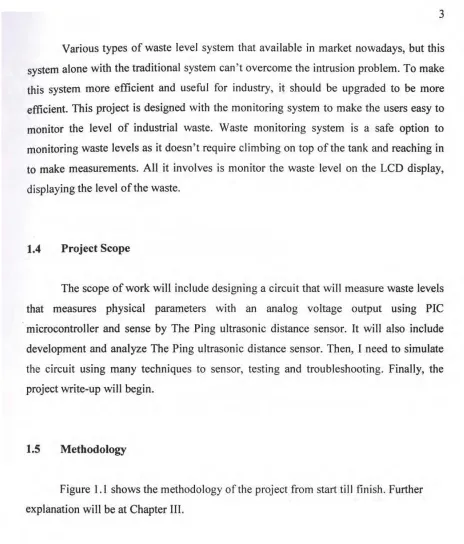
Figure 1.1 shows the methodology of the project from start till finish. Further explanation will be at Chapter III.
[image:17.588.81.545.53.597.2]4
Figure 1.1: Methodology of the project.
1.6 Thesis Outline
Chapter I gave an introduction about the project as well as problem statement, objective and project scope for project.
Chapter 2 is a literature review where the main part of waste level sensor will be described and understanding all components that will be used for this project. The purpose ofthis chapter is to provide an overview the scope of study for this project.
5
Chapter 4 is the result and discussion where all the preliminary result of the
analysis will be shown. Discussion and observation of the outcome of the research in
relation to evidences obtained from project and theories will be made in this chapter.
Chapter 5 is conclusion for this project, which describe the overall project based
on the observation of the result obtained and summarize the entire project. This chapter
also discusses the recommendation for future planning.
CHAPTER II
LITERATURE REVIEW
This chapter consists of some information about water level sensor and also an overview of the literature that has been published in relation to the waste level sensors.
2.1 Components Used in Waste Level Sensor
2.1.1 Microcontroller PIC16F877 A
PIC is a family of Harvard architecture microcontrollers made by Microchip Technology, derived from the PIC 1650 originally developed by General Instrument's Microelectronics Division. The name PIC was originally an acronym for "Programmable Intelligent Computer".
7
The PIC architecture is distinctively minimalist. It is characterized by the
following features with separate code and data spaces (Harvard architecture). It also has
a small number of fixed length instructions.
Most instructions are single cycle execution (4 clock cycles), with single delay
cycles upon branches and skips. It has a single accumulator (W), the use of which (as
source operand) is implied (i.e. is not encoded in the opcode). All RAM locations
function as registers as both source and/or destination of math and other functions.
Other than that, this microcontroller has a hardware stack for storing return
addresses also has a fairly small amount of addressable data space (typically 256 bytes),
extended through banking. Data space mapped CPU, port, and peripheral registers.
The program counter is also mapped into the data space and writable (this is used
to synthesize indirect jumps). Unlike most other CPUs, there is no distinction between
"memory" and "register" space because the RAM serves the job of both memory and
registers, and the RAM is usually just referred to as the register file or simply as the
registers.
This PIC is particularly suited to implementation of fast lookup tables in the
program space. Such lookups are 0(1) and can complete via a single instruction taking
two instruction cycles. Basically any function can be modeled in this way. Such
optimization is facilitated by the relatively large program space of the PIC and by the
design of the instruction set, which allows for embedded constants.
To summarize, a microcontroller contains (in one chip) two or more of the
following elements in order of importance:
I. Instruction set.
ii. RAM.
111. ROM, PROM or EPROM.
IV. 1/0 ports.
8
v. Clock generator.
VI. Reset function.
vii. Watchdog timer.
viii. Serial port.
ix. Interrupts.
x. Timers.
xi. Analog-to-digital converters.
xii. Digital-to-analog converters.
PIC stands for 'Peripheral Interface Controller', general instrument as small, fast,
inexpensive embedded microcontroller with strong input/output capabilities. The
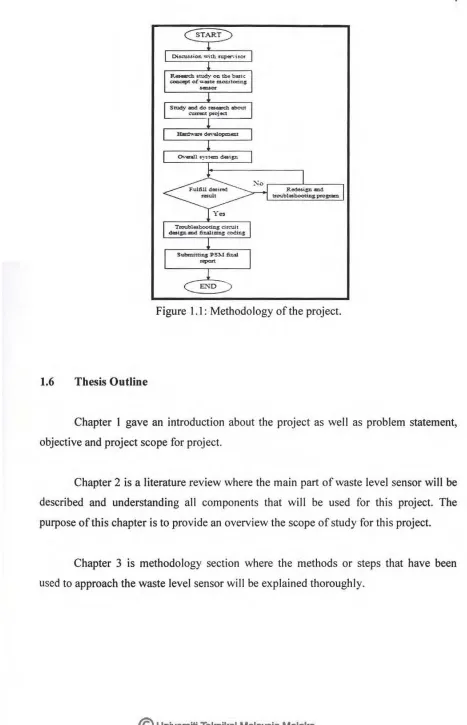
PIC16F877A is CMOS Flash-based 8 bit microcontroller. It packs into 40-pin package
with 3 ports for input/output which are Port A, Port B, Port C and Port D. In this project,
PIC16F877 A will be use. PIC I 6F877 A is in either baseline core or mid-range core
devices in the PIC's family core architecture. PIC I 6F877 A also have enhanced core
features, eight-level deep stack, and multiple internal and external interrupt sources.
PIC18F877A has been chosen because of its USART (Universal Serial
Asynchronous Receiver Transmitter) function. In this project, USART is used to
communicate between hardware and PC serial port. The details explanation of USART
function will be discussed in the next sub-chapter.
Besides, this microcontroller also has input/output port just enough for the
MCLRM>P- RAO/ANO-
RA1/A.N1RA2JAN2NR'Et
RASINWSs
RBliROIAN5
-
RE1JWWAN.6-
RE2JCSIAN7V s s
OSCHCLKlN OSC2/CU<OUT RCOfT10SOIT1CKI
RC11T10SIJCCP2
-- RSeiPGC _ . RBS ... RB4
- RB31PGM
- v s a
- RD71PSP7
-~oe/P:Pa:
- bSIP PS
[image:23.588.169.485.91.397.2]- RD41PSP4 - RC7/RXIDT - RCS/TXICK - RC51800 - RC41SO\ISDA - RD31PSP3 - R02A=ISP2
Figure 2.1: Pin Diagram of PIC 16F877A.
2.1.2
Ultrasonic Sensor
9
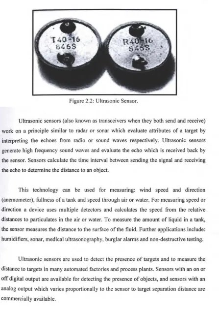
Ultra means "beyond" and sonic means "sound". Ultrasonic refers to sound waves that have higher frequency than the human audible range. The sound waves whose frequency lies above the audible frequency of 20 kHz are called Ultrasonic waves. Ultrasonic sensors can detect small objects at considerable distances. They are able to disregard disturbing backgrounds and functions in fog, dust, dirt or extreme lighting is possible. They can detect any soft and hard materials.
No correction factors have to be applied and color does not matter. In this project used two ultrasonic sensors. One is ultrasonic transmitter and the other is ultrasonic receiver. They transmit and receive the signal with 40KHz frequency.
10
Figure 2.2: Ultrasonic Sensor.
Ultrasonic sensors (also known as transceivers when they both send and receive) work on a principle similar to radar or sonar which evaluate attributes of a target by interpreting the echoes from radio or sound waves respectively. Ultrasonic sensors generate high frequency sound waves and evaluate the echo which is received back by the sensor. Sensors calculate the time interval between sending the signal and receiving the echo to determine the distance to an object.
This technology can be used for measuring: wind speed and direction (anemometer), fullness of a tank and speed through air or water. For measuring speed or direction a device uses multiple detectors and calculates the speed from the relative distances to particulates in the air or water. To measure the amount of liquid in a tank, the sensor measures the distance to the surface of the fluid. Further applications include: humidifiers, sonar, medical ultrasonography, burglar alarms and non-destructive testing.
[image:24.588.106.554.73.708.2]