International Journal of Innovative Technology and Exploring Engineering (IJITEE) ISSN: 2278-3075,Volume-8 Issue-6, April 2019
Abstract. The PMBLDCM is utilized to drive a mechanical gadget heap of Associate in Nursing cooling through a three-stage VSI encouraged from a controlled DC interface voltage. A buck half-connect DC-DC gadget is utilized as a solitary stage Power issu Correction (PFC) gadget for encouraging a Voltage supply electrical converter (VSI)
principally based static magnet Brushless DC
Motor(PMBLDCM) drive. “The forepart of this ozone depleting substance gadget might be a Diode Bridge Rectifier (DBR) bolstered from single-stage AC mains. The speed of the mechanical gadget is managementled to accomplish vitality protection utilizing an idea of the voltage control at DC connect corresponding to the required speed of the PMBLDCM. so the VSI is worked exclusively as Associate in Nursing electronic commutator of the PMBLDCM. The stator curl flow of the PMBLDCM all through advance change of reference speed is controlled by a rate electrical circuit for the reference voltage at DC interface. The arranged PMBLDCM drive with voltage the executives based ozone harming substance gadget is planned, sculpturesque Associate in Nursingd its execution is reenacted in Mat lab-Simulink surroundings for a forced air system mechanical gadget driven through an one.5 kW, 1500 cycles for
each moment PMBLDC engine.” The examination
consequences of the arranged speed the executives subject square measure presented to exhibit Associate in Nursing enhanced power of the arranged drive framework with ozone depleting substance highlight in wide determination of the speed Associate in Nursingd an info AC voltage.
Keywords: “Power Factor Correction (PFC), Voltage Source Inverter (VSI), Permanent Magnet Brushless DC Motor (PMBLDCM), Mat lab- Simulink, Diode Bridge Rectifier (DBR”)
I.INTRODUCTION
Permanent magnet brushless “DC motors (PMBLDCMs) square measure most popular motors for a mechanical device of Associate in Nursing air-conditioning (Air-Con) system thanks to its options like high potency, wide speed vary and low maintenance needs. The operation of the mechanical device with the speed management ends up in Associate in Nursing improved potency of the system whereas maintaining the temperature within the cool zone at the set reference systematically” [1]. the prevailing air conditioners largely have a single-phase induction motor to drive the mechanical device in „on/off‟ management mode. This ends up in raised losses due to frequent „on/off‟ operation with
Revised Manuscript Received on April 07, 2019.
V Mani Kumar, Department of EEE, Godavari Institute of Engineering and Technology (A), Rajahmundry, India,
D Ravi Kishore, Department of EEE, Godavari Institute of Engineering and Technology (A), Rajahmundry, India,
raised mechanical and electrical stresses on the motor, thereby poor efficiency and reduced lifetime of the motor.
“The PMBLDCM “drive, fed from a single-phase AC mains through a diode bridge rectifier (DBR) followed by a DC link condenser, suffers from power quality (PQ)” disturbances like poor power issue (PF), raised total harmonic distortion (THD) of current at input AC mains and its high crest issue (CF). it's chiefly thanks to uncontrolled charging of the DC link condenser which ends up in a very periodical current wave having a peak price over the amplitude of the fundamental input current at AC mains. Moreover, the PQ standards for low power equipment‟s emphasize on low harmonic contents and close to unity power issue current to be drawn from AC mains by these motors” [2] Therefore, the projected theme to be used of an influence issue correction (PFC) “topology amongst numerous accessible topologies is nearly inevitable for a PMBLDCM drive. Most of the prevailing systems use a lift device for PFC as the front-end device Associate in Nursingd an isolated DC-DC device to provide desired output voltage constituting a two-stage PFC drive. The DC-DC device employed in the second stage is sometimes a fly back or forward device for low power applications and a full-bridge device for higher power applications”. In order to enhance the ability issue, some device taking leading power ought to be connected in parallel with the load. One of such devices will be a electrical condenser. The electrical condenser attracts a number one current and partially or fully neutralizes the lagging reactive part of load current. This raises the ability issue of the load. Despite the employment of fine quality check meter instrumentation, high current “flow will typically stay unobserved or underneath calculable by the maximum amount four-hundredth. This severe underestimation causes too high running temperatures of apparatus and nuisance tripping. this can be just because the average reading check meters normally employed by maintenance technicians don't seem to be designed to accurately live distorted currents and might solely give indication of the condition of the availability at the time of checking. Power quality conditions modification ceaselessly and solely instruments giving true RMS activity of distorted waveforms and neutral currents will give the right measurements to accurately confirm the ratings of cables, bus bars AND circuit breakers. High harmonic environments will manufacture sudden and dangerous neutral currents. in a very balanced system, the fundamental currents can get rid of, but, triple-N‟s can add, therefore harmonic currents” at the third, 9th, 15th etc.
PV System fed Topology for BLDC Motor Drive
with PFC
will flow within the neutral. ancient three part system meters square measure solely ready to calculate the vector of line to neutral current measurements, which can not register actuality reading. Integra 1530, 1560 and 1580 supply a three part four wire versions with a neutral fourth CT permitting true neutral current activity and protection in high harmonic environments.
II. BRUSHLESS DC MOTOR
Brushless Direct Current (BLDC) motors are one of the motor types rapidly gaining popularity. BLDC motors are used in “industries such as Appliances, Automotive, Aerospace, Consumer, Medical, Industrial Automation Equipment and Instrumentation. As the name implies, BLDC motors do not use brushes for commutation; instead, they are electronically commutated. BLDC motors have many advantages over brushed DC motors and induction motors. A few of these are”:
• Better speed versus torque characteristics • Highdynamic response
• Highefficiency • Long operating life • Noiselessoperation • Higher speed ranges
In addition, “the ratio of torque delivered to the size of the motor is higher, making it useful in applications where space and weight are critical factors. In this application note, we will discuss in detail the construction, working principle, characteristics and typical applications” of BLDC motors. BLDC motors are a “type of synchronous motor. This potential the magnetic fields generated by means of the stator and via the rotor rotate at the same frequency. BLDC motors do now not experience. BLDC motors come in single-phase, 2-phase and 3-phase configurations. Corresponding to its type, the stator has the identical variety of windings. Out of these, 3-phase motors are the most popular and extensively used. This application word focuses on 3-phase motors. The stator of a BLDC motor consists of stacked metal laminations with windings placed in the slots that are axially cut alongside the inner periphery as shown in Fig.1 [4]. Traditionally, the stator resembles that of an induction motor; however, the windings are dispensed in a exclusive manner. Most BLDC motors have three stator windings linked in star fashion. Each of these windings are constructed with numerous coils interconnected to form a winding. One or extra coils are placed in the slots and they are interconnected to make a winding. Each of these windings are disbursed over the stator periphery to structure an even numbers of poles. There are two sorts of stator windings variants: trapezoidal and sinusoidal motors. This differentiation is made on the foundation of” the interconnection of coils in the stator windings to provide the different kinds of returned Electromotive Force (EMF).
Fig. 1 Stator of BLDC motor
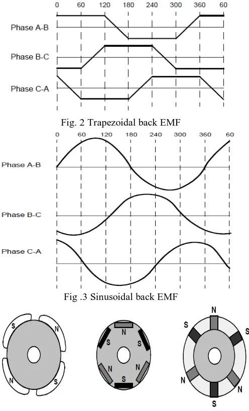
[image:2.595.306.554.277.686.2]As their names indicate, the tetragon motor provides a back voltage in tetragon fashion and also the curved motor‟s back EMF is curved , as shown in Fig. 2 and Fig. 3. additionally to the rear voltage, the section current conjointly has tetragon and curved variations within the various forms of motor. This makes the force output by a curved motor drum sander than that of a tetragon motor. However, this comes with an additional value, because the curved motors take additional winding interconnections thanks to the coils distribution on the stator coil bound, thereby increasing the copper intake by the stator windings. relying upon the management power provide capability, the motor with the right voltage rating of the stator are often chosen. 48 volts, or less voltage rated motors square measure utilized in automotive, robotics, small arm movements and shortly. Motors with one hundred volts, or higher ratings, square measure utilized in appliances, automation and in industrial applications.
Fig. 2 Trapezoidal back EMF
[image:2.595.79.261.689.771.2]Fig .3 Sinusoidal back EMF
Fig. 4 Rotor magnet cross sections
International Journal of Innovative Technology and Exploring Engineering (IJITEE) ISSN: 2278-3075,Volume-8 Issue-6, April 2019
It is important to know the rotor position in order to understand which winding will be energized following the energizing sequence. Rotor position is sensed using Hall effect sensors embedded into the stator.” “Most BLDC motors have three Hall Sensors embedded into the stator on the non-driving end of the motor. Whenever the rotor magnetic poles pass near the Hall sensors, they give a high or low signal, indicating the N or S pole is passing near the sensors. Based on the combination of these three Hall sensor” signals, the exact sequence of commutation can be determined[5].
III. SINGLE STAGE P.F.C CONVERTER The PMBLDCM “drive, fed from a single-phase AC mains through a diode bridge rectifier (DBR) followed by a DC link capacitance, suffers from power quality (PQ) disturbances like poor power issue (PF), multiplied total harmonic distortion (THD) of current at input AC mains and its high crest issue (CF)”. it's principally thanks to uncontrolled charging of the DC link capacitance which ends up in an exceedingly periodical current undulation having a peak price above the amplitude of the fundamental input current at AC mains. Moreover, the PQ standards for low power equipment‟s emphasize on low harmonic contents and close to unity power issue current to be drawn from AC mains by these motors [2].
Therefore, the planned theme to be used of an influence issue correction (PFC) topology amongst numerous out there topologies is sort of inevitable for a PMBLDCM drive. Most of the present systems use a lift convertor for greenhouse emission as the front-end convertor associate degreed an isolated DC-DC convertor to provide desired output voltage constituting a two-stage PFC drive. The DC-DC convertor utilized in the second stage is typically a fly back or forward convertor for low power applications and a full-bridge convertor for higher power applications.
However, these 2 “stage greenhouse emission converters have high price and quality in implementing 2 separate switch-mode converters, so one stage convertor combining the greenhouse emission and voltage regulation at DC link is a lot of in demand, The single-stage greenhouse emission converters operate with only 1 controller to manage the DC link voltage at the side of the ability factor correction. The absence of a second controller includes a larger impact on the performance of single-stage greenhouse emission converters and needs a style to control over a way wider vary of operational conditions”. For the planned voltage controlled drive, a half-bridge buck DC-DC convertor is chosen due to its high power handling capability as compared to the only switch converters.
Moreover, it's shift losses reminiscent of the only switch converters as only 1 switch is operational at any instant of your time. It may be operated as a single-stage power issue corrected (PFC) convertor once connected between the VSI and therefore the DBR fed from single-phase AC mains, besides dominant the voltage at DC link for the specified speed of the Air-Con mechanical device [3].
IV. PROPOSED SPEED CONTROL SCHEME OF PMBLDC MOTOR FOR AIR CONDITIONER
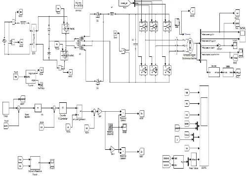
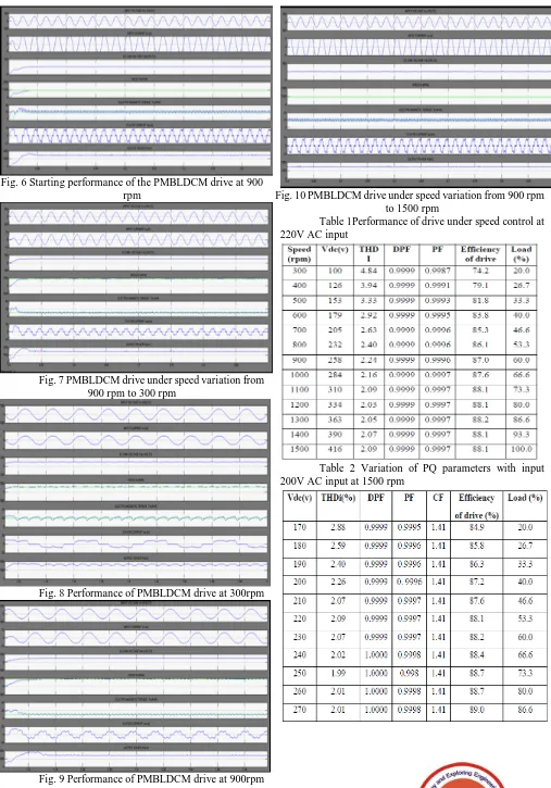
[image:3.595.309.558.452.630.2]The simulation circuit of projected drive for magnet brushless dc motor is shown in below fig. 5. The PMBLDCM drive, fed from a single-phase AC mains through a diode bridge rectifier (DBR) followed by a DC link capacitor. For the projected voltage controlled drive, a half-bridge buck DC-DC device is chosen due to its high power handling capability as compared to the only switch converters. It is operated as a single-stage power factor corrected (PFC) device once connected between the VSI and therefore the DBR fed from single-phase AC mains, besides dominant the voltage at DC link for the required speed of the Air-Con mechanical device. The projected “PMBLDCM drive is sculptured in Mat lab- Simulink surroundings associate degreed evaluated for an air-con compressor load. The mechanical device load is taken into account as a relentless force load adequate rated force with the speed control needed by air-con system. A 1.5 power unit rating PMBLDCM is employed to drive the air conditioning compressor, speed of that is controlled effectively by dominant the DC link voltage. The careful knowledge of the motor and simulation parameters square measure given in Appendix. The performance of the projected fluorocarbon drive is evaluated on the premise of various parameters like total harmonic distortion (THD) and therefore the crest issue (CF) of this at input AC mains, displacement power issue (DPF), power issue (PF) and potency of the drive system at completely different speeds of the motor. Moreover, these parameters are evaluated for variable input AC voltage at DC link voltage of 416 V that is resembling the rated speed (1500 rpm) of the PMBLDCM”. The results square measure shown in Fig. 6 and Fig. 7 and Tables one &.2 to demonstrate the effectiveness of the projected PMBLDCM drive during a wide selection of speed and input AC voltage.
Fig. 6 Starting performance of the PMBLDCM drive at 900 rpm
Fig. 7 PMBLDCM drive under speed variation from 900 rpm to 300 rpm
[image:4.595.47.554.45.770.2]Fig. 8 Performance of PMBLDCM drive at 300rpm
Fig. 9 Performance of PMBLDCM drive at 900rpm
Fig. 10 PMBLDCM drive under speed variation from 900 rpm to 1500 rpm
Table 1Performance of drive under speed control at 220V AC input
International Journal of Innovative Technology and Exploring Engineering (IJITEE) ISSN: 2278-3075,Volume-8 Issue-6, April 2019
VI. CONCLUSION
A new speed management strategy of a PMBLDCM drive is valid for a mechanical device load of associate degree cooling that uses the reference speed as the same reference voltage at DC link. “The speed management is directly proportional to the voltage management at DC link. the speed electric circuit introduced within the reference voltage at DC link effectively limits the motor current among the required price throughout the transient condition (starting and speed control). the extra fluorocarbon feature to the planned drive ensures nearly unity PF in big selection of speed and input AC voltage. Moreover, power quality parameters of the planned PMBLDCM drive area unit in conformity to a world customary IEC 61000-3-2. The proposed drive has incontestable smart speed management with energy economical operation of the drive system within the wide range of speed and input AC voltage. The planned drive has been found as a promising candidate for a PMBLDCM driving Air-Con load in 1-2 kW power vary.Through this project work we've created an effort to research Power Factor” Correction convertor with the assistance of simulations. In future the hardware implementation of the fluorocarbon circuit will be done and its results obtained in real – time things may be compared with the simulation results.
REFERENCES
1. T. Kenjo and S. Nagamori, „Permanent Magnet Brushless DC Motors‟,
Clarendon Press, Oxford, 198
2. T. J. Sokira and W. Jaffe, „Brushless DC Motors: Electronic
Commutation and Control‟, Tab Books USA,
3. J. R. Hendershort and T. J. E. Miller, „Design of Brushless Permanent-
Magnet Motors‟, Clarendon Press, Oxford, 1994
4. J. F. Gieras and M. Wing, „Permanent Magnet Motor Technology –
Design and Application‟, Marcel Dekker Inc., New York, 2002
5. B. Singh, B. N. Singh, A. Chandra, K. Al-Haddad, A. Pandey and D. P.
Kothari, “A review of single-phase improved power quality AC-DC converters”IEEE Trans. Industrial Electron. vol. 50, no. 5, pp. 962 –981, Oct. 2003
6. B. Singh and S. Singh, “Single-phase power factor controller topologies
for permanent magnet brushless dc motor drives,” IET Power Electron., vol. 3, no. 2, pp. 147–175, Mar. 2010.
7. C. L. Xia, Permanent Magnet Brushless DC Motor Drives and
Controls. Hoboken, NJ, USA: Wiley, 2012.
8. P. Pillay and R. Krishnan, “Modeling of permanent magnet motor drives,”
IEEE Trans. Ind. Electron., vol. 35, no. 4, pp. 537–541, Nov. 1988.
9. M. A. Rahman and P. Zhou, “Analysis of brushless permanent magnet
synchronous motors,” IEEE Trans. Ind. Electron., vol. 43, no. 2, pp. 256– 267, Apr. 1996.
10. J. Moreno, M. E. Ortuzar, and J. W. Dixon, “Energy-management system
for a hybrid electric vehicle, using ultra capacitors and neural networks,” IEEE Trans. Ind. Electron., vol. 53, no. 2, pp. 614–623, Apr. 2006.
11. Y. Chen, C. Chiu, Y. Jhang, Z. Tang, and R. Liang, “A driver for the
singlephase brushless dc fan motor with hybrid winding structure,” IEEE Trans. Ind. Electron., vol. 60, no. 10, pp. 4369–4375, Oct. 2013.
12. X. Huang, A. Goodman, C. Gerada, Y. Fang, and Q. Lu, “A single sided
matrix converter drive for a brushless dc motor in aerospace applications,” IEEE Trans. Ind. Electron., vol. 59, no. 9, pp. 3542–3552, Sep. 2012.
13. H. A. Toliyat and S. Campbell, DSP-based Electromechanical Motion
Control. New York, NY, USA: CRC Press, 2004.
14. N. Mohan, T. M. Undeland, and W. P. Robbins, Power Electronics: