International Journal of Innovative Technology and Exploring Engineering (IJITEE) ISSN: 2278-3075,Volume-8 Issue-6, April 2019
Abstract: In this paper an Archimedean spiral reconfigurable antenna is presented for wireless communication applications of LTE 33-37, Mobile terminals, industrial, scientific and medical group (ISM), PCS Band, UMTS, Widespread Tunable Range, Defense and scientific, IOT, Radio Altimeters etc., The Dimension of designed proposed antenna are\ 40mm×35 mm on FR4 epoxy with thickness of 0.8 and dielectric constant 4.4. The proposed antenna takes a spiral element fed by a feeding line. For switching purpose, PIN diodes are utilized in this design. The proposed antenna can be operating at different frequencies basing on the Switching ON and OFF state of PIN Diodes.The study has shown that the designed antenna can reduce the complete antenna size and improving the bandwidth and also operating at different frequencies. There is a good matching in between measured and simulated results.
Index Terms: Archimedean Spiral, ISM Band, PIN Diode, Frequency Reconfigurability, PCB Band.
I. INTRODUCTION
Wireless communications are growing very rapidly in past years and communication devices are becoming very portable. As day by day there has been a tremendous growth in wireless communications particularly in the field of reconfigurable antennas. Reconfigurable antenna means a antenna which supports different operating frequencies range bands [1]. By using reconfigurable antenna, we may easily change to different operating frequency band. From this not only decreases the size of a transmitter and receiver antenna but also reduce in costs by replacing single antenna in the place of multiple antennas [2]. The change of frequency, polarization and radiation pattern can be easily done in reconfigurable antenna. The first experiment on reconfigurable antennas focused by Schaubert in 1983. From then onwards reconfigurable antennas has a different application but all of them are based on switching mechanism. In past frequency reconfigurable antenna designs has been projected to obtain large tuning ranges by using different tuning elements and antenna topologies.
Revised Manuscript Received on April 07, 2019.
N.V.K Ramesh, Research Center, Department of ECE, Koneru Lakshmaiah Education Foundation, A.P, India
B.T.P. Madhav, Research Center, Department of ECE, Koneru Lakshmaiah Education Foundation, A.P, India
P.V. Ramana Rao, Research Center, Department of ECE, Koneru Lakshmaiah Education Foundation, A.P, India
S. Salma, M. Mahaveer, Research Center, Department of ECE, Koneru Lakshmaiah Education Foundation, A.P, India
K. Manisha, Research Center, Department of ECE, Koneru Lakshmaiah Education Foundation, A.P, India
N.V. Sai Santhosh, Research Center, Department of ECE, Koneru Lakshmaiah Education Foundation, A.P, India
The field provided for installation of other antennas in the electronic devices are moreover smaller. So, it is difficult to install multiple antennas for pattern diversity and polarization at a one terminal. When compared with other multiband antennas, reconfigurable antennas mainly preferred basically because it offer characteristic advantages like little in size, low price and mainly it can function at multiple band [3] and [4]. It has better efficiency. The inspiration for implementing a reconfigurable antenna is because of its properties. By eliminating the use of different antennas so it provides rise in degrees of operational freedom that enlarge system efficiency. Reconfigurability is a significant aspect for wireless and satellite communications [5]. Also, in radar applications, reconfigurability of antenna is essential for multi-function operation [6]. The architecture of reconfigurable antenna uses limited area by considering the merit of combined different functionality antennas into single antenna. So moreover, there is a reduction in area occupied by different antenna elements and there is an improvement in the performance and purpose. Within small antenna which has more functionality has vast range of applications in space communications.
The spiral antenna was the mostly used antenna because of its compact form factor and superior performance characteristics. Spiral antenna has constant input impedance and are capable of less than 2:1 Voltage fixed wave ratio. The proposed antenna design consists of Archimedean spiral antenna [7] and [8] which is commonly used as broad-bandwidth antennas. Archimedean spiral antennas are generally operating in the range of 0.1 GHz to 40 GHz. They utilized to radiate in the either sides of the spiral plane, where the unidirectional pattern is essential in several circumstances.
Reconfigurability is possible only when PIN diodes must include in the antenna architecture. The current study is also pointed the usage of PIN diode switch technology in combination with printed antenna geometry in order to obtain different bands and polarization applications. PIN diodes have many advantages like good reliability, compact size, low cost. PIN diodes have high switching speed and it can easily make into a simple switch [9] and [10]. The operating frequency cannot be look over constantly because PIN diodes commonly shift between two pre-determined states namely ON and OFF. Switching ON and OFF effects the surface current path length and hence mode of operation varies. By monitoring the state of PIN diodes, the antennas can shift between several frequencies [11-25].
Design and Analysis of Archimedean Spiral
Reconfigurable Antenna
II. ANTENNADESIGNANDITSGEOMETRY For modern Wireless Communications the antenna should be in small size to reduce the weight of the equipment. The designed antenna is fabricated on FR4 Substrate with permittivity of 4.4 along with loss tangent of 0.02. The Fig.1 illustrations the designed antenna with all parameters are given as Ls=40 mm, Ws=35mm, L1=13mm, L2=5.4mm, W1=1.5 mm, W2=1.5mm, L3=11mm, W3=2mm, h=0.8mm, Rslot=14mm. An Archimedean Spiral planar curve is projected on the Substrate with thinness of 0.8 mm. The spiral antenna each arm is defined as equation below [26-30], [1]
Where r is the radius of the antenna which increases linearly with ,
is the angle between the spiral arm’s, α is the constant that controls the rate at which the spiral flares out. The phase difference between primary and another arm is 180 degrees. The radius and constant are same as like the first arm.
Fig.1 Proposed Archimedean Spiral Reconfigurable antenna. (a) Front plane (b) Ground plane.
The feed line with 50 ohm is inserted with the thickness of 0.8mm and width 1.5mm on the substrate material. 4 PIN diodes D1, D2, D3 and D4 with length and width of 1.35mm×0.35mm are used to attain multi band reconfigurable antenna. The dimensions of the designed Archimedean Spiral Reconfigurable antenna are presented in the Table.1 with antenna parameters in dimensions. The feed
line width ‘W1’ which is dependent on the increase
proportion of ‘α’ is given as below in the equation,
∴
W1 = (α × π) – Rslot [2]The proposed spiral antenna turns can be calculated in terms of ‘N’ in the below equation as,
∴
max1
slot
slot
r
R
N
W
R
[3]Where
r
max is the maximum length between boundary and center of the spiral andR
slot is the radius of the slot.Antenna Parameters
Dimensions in mm
L s 40
W s 35
L 1 13
L 2 5.4
L 3 11
W 1 1.5
W 2 1.5
W 3 2
h 0.8
N 2.5
Rslot 14
Table: 1 Dimensions of Designed antenna III. RESULTS&DISCUSSIONS.
The assurance of structured recurrence reconfigurable antenna with Archimedean spiral regarding reflection coefficient, radiation design, current conveyance, 3D polar plots and Recurrence Versus addition and productivity is introduced by utilizing Ansys software HFSS. In designed antenna four PIN diodes are placed in the spiral part. The sixteen various switching conditions are obtained from the four PIN diodes for ON and OFF. From the above mentioned sixteen switching cases, similar cases are eliminated, and the remaining cases are categorised into low and high frequencies. The low and high frequency case exhibits 3 and 2 bands of resonant frequencies. The comparison of simulated various switching conditions for low and high frequencies are presented in Fig. 2 and 3.
International Journal of Innovative Technology and Exploring Engineering (IJITEE) ISSN: 2278-3075,Volume-8 Issue-6, April 2019
In case 4 antenna resonate at 1.47- 1.57 GHz, 4.10 -4.69 GHz and 7.04-7.56 GHz with return loss of (-1.31 to -1.38), (-5.65 to -19.91) and (-8.62 to -16.25) dB.
In case 5 antenna resonate at 2.18- 2.2 GHz, 4.37 -4.83 GHz and 7.08-7.96 GHz with return loss of (-7.44 to -5.11), (-8.70 to -14.04) and (-8.39 to -9.67) dB. In case of lower frequencies proposed antenna has wide range of applications in L, S and C band. The switch conditions of the above cases from 1 to 5 are presented in the Table. 2.The examination of reenacted reflection coefficients of the above cases from 1 to 5 are displayed in Fig.2. By utilizing HFSS software, the radiation examples of proposed reconfigurable antenna with four diodes are simulated. The radiation patterns are used to characterize the radiated energy by the antenna. The radiated power is characterized graphically. The designed antenna radiation characteristics of E & H-plane are plotted at
resonant frequencies of
1.47/2.16/4.10/4.69GHz.omnidirectional radiation pattern is attained in E & H-plane has the bi directional radiation patterns. The E & H plane patterns are plotted in below Fig.3.
Table: 2 Low frequency switching cases with resonant frequencies.
Fig.2. Comparison of simulated reflection coefficient of
low frequencies at various switching conditions.
Fig.3. Radiation pattern of the Antenna proposed at different operating banads in E & H plane in 2D (a) 1.47 GHz (b) 2.16 GHz (c) 4.10 GHz and (d) 4.69 GHz.
Fig.4. Radiation pattern of the Antenna proposed at different operating bands in E & H planes in 3D (a) 1.47 GHz (b) 2.16 GHz(c) 4.10 GHz and (d) 4.69 GHz.
Generally, Gain characterizes the efficiency of the antenna. The power transferred in the peak radiation direction is described by antenna gain. The gain of this antenna is considered as function of angles. The 3D polar gain at resonating frequencies 1.47/2.16/4.10/4.69GHz are simulated as shows in below Fig. 4.
Cases Switch 1
Switch 2
Switch 3
Switch 4
Resonant frequencies
1 OFF OFF OFF OFF 2.07, 4.31-4.81,
7.05–7.2 GHz
2 OFF OFF OFF ON 2.10, 4.33–4.8,
7.10 – 7.9 GHz
3 OFF OFF ON ON 2.04–2.16,
4.24-4.87, 7.11-7.93 GHz
4 OFF ON ON OFF 1.47-1.57,
4.10-4.69, 7.04-7.56 GHz
5 ON OFF ON ON 2.18-2.22,
The proposed antenna with spiral of the currents is hugely concentrated. Along the feed element and spiral patch, the maximum amount of current is appropriated. The current distributions of this antenna is uniform and good. The current distributions of this antenna are presented in the below Fig. 5.
Fig: 5 Current distributions at resonating frequencies (a) 1.47GHz (b) 2.16GHz (c) 4.10GHz (d) 4.69GHz 3.2 HIGH FREQUENCY SWITCHING CASES.
The proposed antenna covers the high frequency ranges at various switching conditions. In Case 1 antenna resonates at 4.14 -4.65 GHz and 6.94-7.73 GHz with return loss of (-10.05 to -11.38) and (-9.56 to – 9.49) dB. In case 2 antenna resonate at 4.10 -4.65 GHz and 6.93-7.59 GHz with return loss of (-9.8 to -11.3) and (-9.57 to -10.4) dB. In case 3 antenna resonate at 4.08 -4.72 GHz and 7.01-7.66 GHz with return loss of (-10.13 to -8.79) and (-10.38 to -10.56) dB. In case 4 antenna resonate at 4.36 -5.02 GHz and 7.10-7.88 GHz with return loss of (-8.70 to -10.35) and (-10.05 to -11.38) dB. In case 5 antenna resonate at 4.39 -4.84 GHz and 7.11-7.90 GHz with return loss of (-10.12 to -11.47) and (-9.86 to -10.00) dB. In case of high frequencies proposed antenna has wide range of applications in S and C band. The switching conditions of the above cases from 1 to 5 are presented in the Table. 3. The comparison of simulated reflection coefficients of the above cases from 1 to 5 are presented in Fig.6.
Cases Switch 1
Switch 2
Switch 3
Switch 4
Resonant frequencies
Case 1
ON OFF OFF OFF 4.14-4.65,
6.94-7.73GHz Case
2
OFF OFF ON OFF 4.10-4.65,
6.93-7.59GHz Case
3
ON ON OFF OFF 4.08-4.72,
7.01-7.66GHz Case
4
OFF ON OFF OFF 4.36-5.02,
7.10-7.88GHz Case
5
ON ON ON ON 4.39-4.84,
[image:4.595.48.291.134.358.2]7.11-7.90GHz
Table: 3 High frequency switching cases with resonant frequencies.
Fig. 6. Comparison of simulated reflection coefficient of high frequencies at various switching conditions.
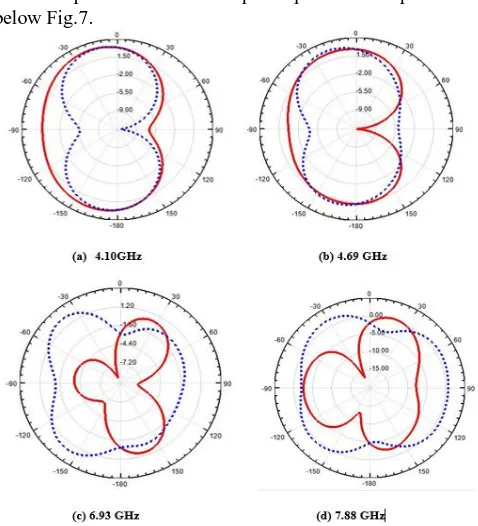
By using HFSS software, the radiation pattern of this reconfigurable antenna with four diodes are simulated.The radiation patterns are utilized to characterize radiated energy by antenna.The radiated power is characterized graphically. This antenna radiation characteristics in E & H plane are plotted at resonant frequencies of 4.10/4.69/6.93/7.88 GHz. Omni directional radiation is obtained in E & H plane has bi directional radiation pattern.The E & H plane patterns are plotted in below Fig.7.
Fig.7. Radiation pattern of the antenna proposed at different operating bands in E & H planes in 2D (a) 1.47
[image:4.595.308.547.411.674.2]International Journal of Innovative Technology and Exploring Engineering (IJITEE) ISSN: 2278-3075,Volume-8 Issue-6, April 2019
Fig.8. Radition pattern of the Antenna proposed at different operating bands in E & H plane in 3D (a) 4.10
GHz (b) 4.69 GHz (c) 6.93 GHz and (d) 7.88 GHz. Generally, the gain characterizes the efficiency of the antenna. The power transferred in peak radiation direction is described by antenna gain. The gain of antenna is considered as function of angle.The 3D polar gain at resonating frequencies 4.10/4.69/6.93/7.88 GHz are simulated as show in below Fig. 8. The designed antenna with spiral of the currents is hugely concentrated. Along the feed element and spiral patch, the maximum amount of current is appropriated. The current distributions of the designed antenna is uniform and good.The current distributions of the designed antenna is presented below Fig. 9
.
Fig: 9 Current distributions at resonating frequencies (a) 4.10GHz (b) 4.69GHz (c) 6.93GHz (d) 7.88GHz
The antenna gain characterizes how more power is delivered in direction of peak radiation. The simulated gain of the suggested antenna shown in the fig 10. The suggested antenna shows the peak gain of 3dB at lower resonant frequency of 3.1GHz and 5 dB gain at 4.1GHz higher resonant frequency. The parameter gain is utilized to characterize the distance travel by the wave. The fig.11 is the fabricated antenna which consists of measured reflection coefficient.
Fig: 10 Frequency Vs Gain of the Antenna
Fig: 11 Prototyped antenna (a) Front view (b) Ground view (c) Measured Reflection coefficient of the
prototyped antenna. IVCONCLUSION
By placing four diodes there is good frequencies shifting between them and good return loss is obtained which is less than -10 dB at operating bands. There is good arrangement made in between the measured and simulated results with respect to frequency reconfigurablity. In future the diodes can be placed vertically and study the frequency shifting to attain the wide band ranges for wide range of applications.
ACKNOWLEDGMENT
We are thankful to KLEF for their moral support and DST for their technical support through ECR/2016/000569, and EEQ/2016/000604
REFERENCES
1. B.T.P Madhav, et al,” Frequency reconfigurable monopole antenna with DGS and ISM band applications,” journal of Electrical Engineering, vol.69. pp.293-299,2018.
2. F. Dahalan, et al.,’Frequency-reconfigurable Archimedean spiral antenna,” IEEE antenna and wireless propagation letters, vol.12,pp.1504-1507,2013.
3. B. Piper, et al,” Electromagnetic modeling of conformal wideband and multi-band patch antennas by bridging a solid-object modeler with MoM software,” IEEE Antennas and propagation magazine, vol.46, pp.42-52,2004.
4. C.G.Christodoulou,et al,” reconfigurable antenna for wireless and space applications, ’proceedings of the IEEE, vol.100,pp.2250-2261,2012. 5. M.-I.Lai,et al,”Design of reconfigurable antennas based on an L-shaped
slot and PIN diodes for compact wireless devices,”IET Microwaves, Antennas & propagation,vol.3,pp.47-54,2009.
6. A.Siahcheshm,et al, ”A broadband circularly polarized cavity-backed
Archimedean spiral array antenna for c-band
application,”AEU-International Journal of electronics and
communication,vol.81,pp.218-226,2017.
7. P.Mookiah,et al,”Reconfigurable spiral antenna array for pattern diversity in wideband MIMO communication systems ”in 2008 IEEE Antennas and propagation society International symposium,2008,pp.1-4. 8. C.Won Jung,et al,”Reconfiguarable Scan-beam single-arm spiral antenna intrgrated with RF-MEMS switches,”IEEE transactions on antennas and propagation,vol.54,pp.455-463,2006.
9. T.LI,et al,”Frequecy-reconfigurable bow-tie antenna for
Bluetooth,WiMAX and WLAN applications,”IEEE antennas and Wireless propagation Letters,vol.14,pp.171-174,2015.
10.LHan,et al,”Frequency reconfigurable microstrip patch antenna,” WIT
Transactions on information and communication
technologies,vol.49,pp.423-430,2014.
11.O.A.Mashaal,et al,”ACoplanar Waveguide fed two arm Arichimedian spiralslot antenna with improved bandwidth,”
12.IEEE Transactions on antennas and
propagation,vol.61,pp.939-943,2013.
13.M.A.Babu,et al,”A Dual-polarization reconfigurable antenna with beam switching characteristics fors-band applications,”2006.
14.M.Jenath,et al,Review on frequency reconfigurable antenna for wireless applications,” in 2017 international conference on communication and signal processing(ICCSP),2017,pp.2240-445.
15.K.Murthy,et al,”reconfigurable Notch Band Monopole Slot Antenna for WAN/IEEE-802.11 n applications,”International Journal of Intelligent Engineering and systems,ISSN,pp.2185-3118,2017.
16.B.Madhav,et al,”Frequency Reconfigurable Antenna for Ku-Band
Applications,”ARPN Journal of Engineering and Applied
sciences,ISSN,vol.6608,pp.6527-6532,1819.
17.D.S.Rao,et al,”Microstrip Parasitic Strip oaded Reconfigurable Monopole Antenna,”ARPN Journal of Engineering and Applied sciences,ISSN,vol.6608,pp.1-7,1819.
18.A Manikanta Prasanth,et al,”Analysis of Defected Ground structure Notched Monopole Antenna,”ARPN Journal of Engineering and Applied Sciences,ISSN 1819-6608,vol.10,no.2,Feb-2015,pp.747-752. 19.Harish Kaza,et al,”Novel printed Monopole Trapezoidal Notch Antenna
with S-Band Rejection,”Journal of Theoretical and Applied Information Technology,ISSN:1992-8645,vol.76,no 1,2015,pp.42-49.
20.P.Lakshmikanth,et al,”Printed Log Periodic dipole antenna with Notched filter at 2.45 GHz Frequency for Wireless communication application,”
Journal of Engineering and Applied
sciences,ISSN:1816-949x,vol10,Issue 3,Aug-2015,pp
40-44.DOI:10.3923/jeasci.2015.40.44.
21.D S Ram Kiran,”Novel compact asymmetrical fractal aperture Notch
band Technologies,ISSN 1583-1078,vol 27,issue 2,December
2015,pp.1-12.
22.Habibulla khan,et al,”Novel Sequential Rotated 2x2 Array Notched Circular patch Antenna”Journal of Engineering science and Technology Review,ISSN:1791-2377,vol.8,Issue 4,Dec-2015,pp.73-77.
23.D S Ram kiran,et al,”Coplanar Waveguide Fed Dual Band Notched MIMO Antenna,”International Journal of Electrical andcomputer
Engineering (IJECE),ISSN:2088-8708,vol.6,No.4,August
2016,pp.1732-1741.
24.Y.S.V>Raman,”Analysis of Circularly polarized Notch Band Antenna
With DGS,”ARPN Journal of Engineering and Applied
Sciences,vol.1,No.17,September 2016.
25.Allam Vamsee Krishna,”Planer Switchable Notch Band Antenna With
DGS for UWB Applications,Lecture Notes in Electrical
Engineering,ISSN/;1876-1100,vol 434,2017,pp.509-518.
26.S.S.Mohan Reddy,Et al,Design and analysis of Circular Notch Band
DGS Monopole Antenna,Lecture Notes in Electrical
Engineering,ISSN:1876-1100,vol.434,2017,pp.409-417.
27.Kosuru Murty,et al,”Reconfiurable Notch Band Monopole Slot Antenna for WLAN/IEEE-802.1 ln Applications,International Journal of Intelligent Engineering and systems,ISSN:2185-3118,vol 10,No 6,oct-2017,pp.166-173.
28.Vamseekrishna Allam,Defected Ground Structure Switchable Notch Band Antenna for UWB Applicationssmart Innovation,system and Technologies,vol 77,pp.139-145,2018.
29.M Venkateswara Rao,et al,ANovel Ultra Wideband MIMO Antenna with WIMAX Band Notch Characteristics,Journal of Advanced Research in Dynamical and control systems,vol 9,issue 14,2017,pp.2094-2103. 30.M Venkateswara Rao,et al,”Conformal Band Notched Circular
Monopole Antenna Loaded with Split Ring Resonator,Wireless Antenna
loaded with Split Ring Resonator,Wireless Personal
communications,ISSN:1572-834X,2018,pp.1-12.
31.P Parshasaradhi,et al,”circular monopole Reconfigurable