Page 1 of 91
University of Southern Queensland
Faculty of Engineering and Surveying
The Skid Mounted Substation
A dissertation submitted by
Mr. Thiew Atem
In fulfilment of the requirements of
Courses ENG4111 and ENG4112 Research project
towards the degree of
Bachelor of Engineering (Electrical and Electronic)
Submitted: October, 2011
Page 2 of 91
Abstract
The research undertaken has collated a broad range of technologies and provided a guide to
assist the development of a new improved 66/11 kV skid mounted substation. This
dissertation investigated the impact of modern secondary systems in substations to utilities
and, takes a look at different approaches used by electricity services providers, for migrating
from today’s system to the future ones, typically using Supervisory Control and Data
Acquisition (SCADA) communication systems incorporated with IEC 61850 protocols. This
report covered most of the technical constraints associated with IEC 61850 standards and also
explained the impact it might have on 66/11 kV skid mounted substation design, construction
and operation. The implementation of IEC 61850 standards is possible if it meets the various
Page 3 of 91
University of Southern Queensland
Faculty of Engineering and Surveying
ENG4111 Research Project Part 1 & ENG4112 Research Project Part 2
Limitations of Use
The Council of the University of Southern Queensland, its Faculty of Engineering and Surveying, and the staff of the University of Southern Queensland, do not accept any responsibility for the truth, accuracy or completeness of material contained within or associated with this dissertation.
Persons using all or any part of this material do so at their own risk, and not at the risk of the Council of the University of Southern Queensland, its Faculty of Engineering and Surveying or the staff of the University of Southern Queensland.
This dissertation reports an educational exercise and has no purpose or validity beyond this exercise. The sole purpose of the course "Project and Dissertation" is to contribute to the overall education within the student’s chosen degree programme. This document, the associated hardware, software, drawings, and other material set out in the associated appendices should not be used for any other purpose: if they are so used, it is entirely at the risk of the user.
Professor Frank Bullen Dean
Page 4 of 91
Certification
I certify that the ideas, designs, and experimental work, results, analysis, and conclusions set out in
this dissertation are entirely my own efforts, except where otherwise indicated and acknowledged.
I further certify that the work is original and has not been previously submitted for assessment in
any other course or institution, except where specifically stated.
Thiew Atem
Student No: 0050086166
________
Signature
___________27/10/2011_______________
Page 5 of 91
Acknowledgements
“In all your ways acknowledge him, and he will make your paths straight” (Proverbs 3:6). It
is hard to put into words how much I appreciate the help and support given to me by many
great people during the course of my project. My deepest thanks to university’s supervisor Dr
Fouad Kamel, for guiding me and correcting various documents of mine with care and
attention. He has taken pain to go through the project and make necessary correction as and
when needed.
My deepest sense of gratitude to my work’s project supervisor Mr Kerry Williams and Mr
Darryl Sanders, (ERGON Energy Corporation) for their support and guidance. I would like to
extend my special thanks to ERGON Energy substation design team especially Norm Booth
for his support. I would like to express my sincere acknowledgement in the support and help
provided by Communication and SCADA team Mr Greg Borger and Mr Lou Hill in
particular.
It gives me immense pleasure to acknowledge my parents who tempered each other’s advice
to give me the right mix of keeping my feet on the ground, putting me through school and
believing that I “can do it”. Thank to my brothers, sisters and my friends for their support and
advice and my grandparents for giving me inspiration. I would like to thank Abuk Manyok
Majok and Garang Malual Jok who tirelessly supported and helped me to prepare this thesis.
I would also like to thank staffs and colleagues at the USQ Faculty of Engineering and
Surveying without them this project would have been a distant reality. I also would like to
extend my heartfelt thanks to my elder brother Bul Atem (who always been ahead of his time
and been the greatest mentor and enabler throughout my journey) and Awai Piok Kongor for
providing me with the opportunity to be where I am today. Without them, none of this would
Page 6 of 91
Table of content
Abstract ... 2
Limitations of Use ... 3
Certification... 4
Acknowledgements ... 5
Table of content ... 6
List of figures ... 11
List of table ... 12
Dissertation layout ... 13
Chapter 1 ... 14
1. Introduction ... 14
1.1 The 66/11 kV Skid Mounted Substation ... 16
1.2 Skid Mounted Substation structure and fundamentals ... 17
1.2.1 Mathematical methodology for Skid Mounted Substation ... 18
1.3.0 66/11 kV Skid Mounted Substation Major Components ... 19
1.3.1 The 66 kV Circuit Breaker ... 19
1.3.2 The 66 kV Current Transformer ... 22
1.3.3 66/11 kV Power Transformer ... 23
1.3.3.1 Method of grounding transformer neutral ... 23
1.3.3.2 Tap changer ... 24
Page 7 of 91
1.3.4 The 11 kV Plant ... 28
1.3.4.1 The 11 kV Reclosers ... 28
1.4.0 Skid Mounted Substation ancillary components ... 28
1.4.1 Protection system ... 29
1.4.2 Communication systems ... 30
1.4.3 Skid Mounted Substation control ... 30
1.4.4 Skid Mounted Substation Earthing systems ... 30
1.4.5 AC/DC Supplies Systems ... 32
1.4.6 Skid Mounted Substation lightning protection systems ... 32
1.4.7 Metering functions ... 34
1.4.8 Skid Mounted Substation Safety ... 34
1.4.8.1 Risk associated with Skid Mounted Substation ... 36
1.4.8.2 Control measure ... 36
1.4.9 Environmental safety ... 37
1.5.0 Summary ... 37
Chapter 2 ... 38
New Improved 66/11 kV Skid Mounted Substation ... 38
2.1. Introduction ... 38
2.1.1 Circuit breaker theory ... 39
2.1.2 Gas Insulated Switchgear (GIS) ... 39
2.1.3 Circuit breaker technology ... 40
Page 8 of 91
2.1.5 Indoor Gas Insulated Switchgear (GIS) ... 42
2.1.6 GIS hazards and safety ... 43
2.1.7 Security of GIS ... 44
2.1.8 GIS impact on environment ... 44
2.1.9 Future possibilities ... 45
2.2 Conclusion ... 46
Chapter 3 ... 47
3.1.1 Supervisory Control and Data Acquisition (SCADA) ... 47
3.1.2 Data Type ... 48
3.1.3 Data communication ... 49
3.1.4 Communication network ... 55
3.1.5 Impact of deregulation ... 55
3.1.6 Competition ... 55
3.1.7 Technical development and influence on the data transfer ... 56
3.1.8 New technologies ... 56
3.1.9 Satellite (VSAT) ... 57
3.2. Synchronous digital hierarchy (SDH) ... 57
3.2.1 Integrated services digital network (ISDN) for backup ... 58
3.2.2 Future development ... 58
3.2.2.1 Communication ... 58
3.2.2.2 Network hierarchy ... 58
Page 9 of 91
3.3 Summary and conclusion ... 59
3.3.1 Architecture ... 59
3.3.2 Standardisation ... 60
3.3.3 Protocols ... 60
3.3.4 Data Rates ... 61
3.3.5 Networks ... 61
3.3.6 Managing network ... 61
3.3.7 Integration strategies ... 62
3.3.8 Conclusion ... 62
Chapter 4 ... 63
4.1 The IEC 61850 Standards ... 63
4.1.1 Introduction to IEC 61850 ... 63
4.1.2 The need for IEC 61850 ... 63
4.1.4 Advantages of IEC 61850 ... 65
4.1.5 Goal of IEC 61850 ... 65
4.1.6 The logical interfaces in substation automation ... 66
4.1.7 Logical Nodes (LN) ... 67
4.1.8 Physical Interfaces ... 68
4.1.9 Communication Independent Interface ... 68
4.1.10 Engineering for IEC 61850 standard ... 69
4.1.11 Interoperability features ... 72
Page 10 of 91
4.1.13 Advantages and disadvantages ... 74
4.1.14 Summary ... 74
4.1.15 Conclusion ... 75
Chapter 5 ... 76
5.1 Analysis and recommendation for communication standards ... 76
5.1.1 Substation Automation System (SAS) ... 76
5.1.2 Incorporating SCADA RTU with IEC 61850 communication Standard ... 76
5.1.3 Recommendation ... 77
5.1.4 IEC 61850 network and SCADA legacy architecture ... 78
6. Conclusion ... 81
6.1 Skid Mounted Substation ... 81
6.2 Gas Insulated Switchgear (GIS) ... 82
6.3 The IEC 61850 standard ... 82
6.4 Supervisory Control and Data Acquisition (SCADA) ... 82
6.5 Future improvement ... 83
7. Appendices ... 84
7.1 Appendix B: Timeline ... 86
Appendix C- Glossary ... 88
Page 11 of 91
List of figures
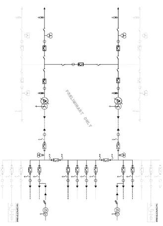
Figure 1: A typical single line diagram for SMS (Ergon Energy, 2011) ... 15
Background ... 16
Figure 2: Skid Mounted Substation (Ergon Energy, 2011) ... 16
Figure 3: A typical 66/11kV zone substation (Ergon Energy, 2011) ... 17
Figure 4: Schematic typical relay-circuit breaker combination ... 19
Figure 5: Total fault clearing time ... 20
Figure 6: A typical outdoor 66kV “live head” circuit breaker (Ergon Energy, 2011) ... 21
Figure 7: A typical outdoor HV Current Transformer (Ergon Energy, 2011) ... 22
Figure 8: A typical earthing of the neutral ... 24
Figure 9: A typical de-energized tap changer ... 25
Figure 10: OLTC with transition resistors type ... 26
Figure 11: OLTC with both diverter and tap selector ... 27
Figure 12: Earth potential (Ergon Energy, 2011)... 31
Figure 13: A typical earth potential variation (Ergon Energy, 2011) ... 32
Figure 14: A typical substation lightning protection (Ergon Energy, 2011) ... 33
Figure 15: Burning substation ... 35
Figure 16: A typical substation clearance and equipment failure (Ergon Energy, 2011) ... 36
Figure 17: SMS diagram (Ergon Energy, 2011) ... 37
Figure 18: A typical GIS switchgear ... 40
Figure 19: 66kV (GIS) Gas Insulated Switchgear (Ergon Energy, 2011) ... 41
Figure 20: A typical GIS switchgear (Ergon Energy, 2011) ... 42
Figure 21: A relocatable GIS switchgear (Ergon Energy, 2011) ... 45
Page 12 of 91
Figure 23: A typical IEC 61850 enable secure substation ... 64
Figure 24: Logical interfaces in Substation automation (CIGRE, 2007) ... 67
Figure 25: A typical basic IED configuration (left) and system specification (right) (CIGRE 2007) .. 70
Figure 26: System configuration and the use of SCD file (CIGRE 2007) ... 71
Figure 27: Specification for IED configuration (CIGRE 2007) ... 72
Figure 28: Configuration interface process (CIGRE 2007) ... 73
Figure 29: Typical substation configuration language ... 77
Figure 30: Typical relay to relay application for legacy architecture ... 78
Figure 31: A typical hardwired performance (UCA, 2011) ... 79
Figure 32: Typical network architecture for IEC 61850 (UCA, 2011) ... 80
Figure 33: A typical IEC network performance (UCA 2011) ... 80
List of table
Background ... 16Table 1: Transformer data specification ... 27
Page 13 of 91
Dissertation layout
Chapter 1: Introduction to general overview about existing 66/11 kV Skid Mounted
Substation
Chapter 2: Described the development of Gas insulated switchgear (GIS) technology and
the types of circuit breaker.
Chapter 3: Concerns with new improved 66/11 kV skid mounted substation design based
on the concept specifications and changes recommended for switchgear,
interfacing of the SCADA control and communication into the control centre
and complying with the general intent of the specification for substations
requirements.
Chapter 4: Provides details of a modern communication technology, the IEC 61850
standards and its impact on substation design, construction and operation.
Chapter 5: Discuss the outcomes and recommendation in both chapter 3 and chapter 4.
Chapter 6: Overall conclusion and future research.
Chapter 7: Appendixes
Page 14 of 91
Chapter 1
This chapter introduced background information about the existing 66/11 kV skid mounted
substation in terms of structure, fundamental, component, interface, function and
communication.
1. Introduction
The aim of this research is to develop a new improved 66/11 kV Skid Mounted Substation a
re-locatable small scale Distribution Substation with a capacity of 10 MVA. The design is
based on the concept specifications and changes recommended for switchgear interfacing
with the SCADA control and communication systems.
This dissertation cover challenges facing the current 66/11 kV skid mounted substations such
as dismantling of outdoor circuit breaker. It will analyse and investigate the advantages and
disadvantages of both the use and impact of available communication technologies inside and
outside the skid mounted substation. The improved design will incorporate features such as
Gas Insulated Switchgear (GIS) and Supervisory Control and Data Acquisition (SCADA) and
Communications that align with the new IEC 61850 standards protocols.
The main objectives of the project are:
1. Review 66/11 kV Skid Mounted Substation design process
2. Introduce the new IEC 61850 protocol to the existing Network
3. Changing the type of circuit breaker
4. Design a new improved 66/11 kV 10 MVA Skid Mounted Substation
The document provides background information about the current 66/11 kV skid mounted
Page 15 of 91
improved 66/11 kV skid mounted substation design and the implications of using different
[image:15.595.136.465.159.614.2]communications technologies in protection and control systems design.
Figure 1: A typical single line diagram for SMS (Ergon Energy, 2011)
Page 16 of 91
Background
1.1
The 66/11 kV Skid Mounted Substation
A skid mounted substation is a fully assembled single transformer substation with an ultimate
firm capacity of typically 10 MVA and is mounted on a fabricated structural skid base for
outdoors use. They are manufactured in a workshop and lifted onto a heavy transport vehicle
for relocating between sites. They are generally used for temporary supply during lengthy
maintenance periods, substation re-builds, other special substation project work, or temporary
demand augmentation needs.
The Skid Mounted Substation (SMS) is based on a modular concept that is designed to be
self-contained and easily transportable. The substation skid is pre-assembled for
simplification of installation and to minimize on-site works, testing, cost and construction
lead time. As shown in figure 2, the skid mounted substation provides the utility with a
flexible method of response for emergency applications such as equipment failure, rapid load
[image:16.595.109.445.489.735.2]increases and weather related disruptions such as cyclones.
Page 17 of 91
1.2 Skid Mounted Substation structure and fundamentals
The existing Skid Mounted Substation (SMS) design consists of a given set of devices that
protect, supervise and operate a part of the system, e.g., 66/11 kV power transformer, 66 kV
circuit breaker and three 11 kV feeder reclosers. The protection and control for the circuit
breaker, reclosers, transformer and Remote Terminal Unit (RTU) are included in the design
and all are reviewed and considered in this project for change to suit the new design.
The 66 kV outdoor switchgear is connected to the outdoor power transformer. The secondary
side 11 kV distribution switchgear includes outdoor reclosers whilst the, protection, SCADA,
metering, communications, DC supplies and other equipment are housed within the
substation outdoor control cubicles. The connection to the local primary distribution network
is done with overhead connections. But an underground cable connection option is available.
The base model includes a SCADA connection system that provides full remote control and
[image:17.595.73.521.430.704.2]monitoring.
Page 18 of 91
1.2.1 Mathematical methodology for Skid Mounted Substation
Transformer rating given Sbt = 10 MVA
High Voltage side Vbl = 66 kV
Low voltage side Vbl = 11 kV
Base phase voltage Vb = ?
Base impedance Zb = ?
Base impedance on HV = ?
Base impedance on LV = ?
Base load current = ?
Solution
Assume star connection
Ib = Sbt/(sqrt3 x Vbl) (1)
= 10000000/(sqrt3 x 66000) = 87.477 A
Vb = 38.105 kV
Zb = 38105/87.477
= 435.601Ω
HV impedance Z = Vb / Ib = 435.6 Ω
LV impedance Z = 12.1Ω
The base value for impedance is given by the value for line to line voltage square divided by
the base MVA (transformer rating). The maximum rated apparent power is typically selected
in this case 10 MVA. In order to achieve magnitude current compensation, individual phase
current is normalized on power transformer side by dividing the base current. The base
Page 19 of 91
1.3.0
66/11 kV Skid Mounted Substation Major Components
1.3.1 The 66 kV Circuit Breaker
Circuit breakers and protective relays are used in combination to detect and isolate faults.
Circuit breakers (CB) are the main making and breaking devices in an electrical circuit that
allow or prevents the flow of power from source to the load. The 66 kV circuit breaker is
capable of supplying a maximum fixed load at a given security level. Under fault conditions,
a monitoring relays send a signal to a breakers to change status. A protective relay detects,
evaluates the fault and determines when the circuit breaker should be open. Closed CB has
sufficient energy to open its contacts stored generally in charged springs. When a protective
relay signals to open the circuit, the stored energy is release causing the circuit breaker to
open with the exception where protective relays are mounted on the CB. The connection
between the relay and the CB is by hard wiring. As shown in figure 4, the important parts of
the circuit breaker are the trip coil, latching mechanism, main and auxiliary contacts.
Page 20 of 91
During fault isolation, the time interval between each event is in an order of a few
milliseconds through the following procedures:
Relay receives information, analyses and determines that the circuit breaker should be
opened.
Relay closes its contacts energizing the trip coil of the circuit breaker.
Circuit breaker is unlatch and opens its main contact under the control of the tripping
spring.
The trip coil is de-energized by opening of the circuit breaker auxiliary contacts.
The main important characteristic in term of protection is the speed in which the main current
is opened after a tripping impulse is received and the capacity of the circuit that the main
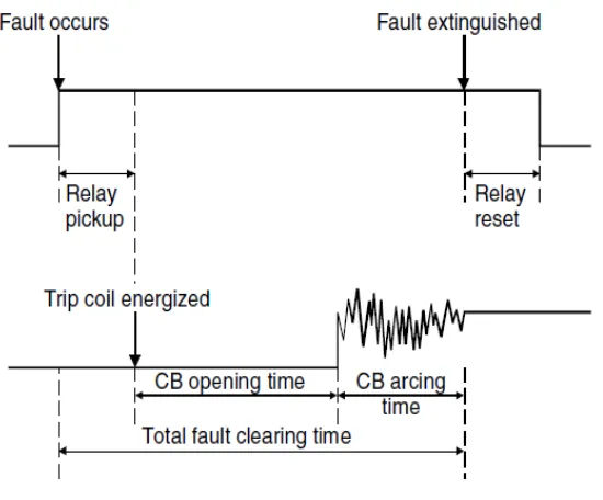
[image:20.595.171.446.408.636.2]contacts are capable of interrupting. Figure 5 shows a typical fault clearing time.
Figure 5: Total fault clearing time
The CB opening time is the time between instant of application of tripping power to the
Page 21 of 91
instant of separation of the main circuit breaker contacts to the instant of arc extinction of
short circuit current. The combination of both opening and arcing time as a result gives total
fault clearing time.
The circuit breaker has a minimum short time fault current rating of 31.5 kA for one second.
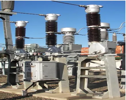
The circuit breaker must be transported separately from the skid mounted substation, due to it “live head” design. Figure 6 shows an example of a typical outdoor “live head” circuit
[image:21.595.75.514.263.609.2]breaker.
Figure 6: A typical outdoor 66kV “live head” circuit breaker (Ergon Energy, 2011)
This project addresses the issue of dismantling the outdoor circuit breaker during relocation
and finds room within the SMS to accommodate the gas insulated (G)IS switchgear. More
Page 22 of 91
circuit breaker (CB) assembly, SF6 gas filling, wiring and testing work is performed on site
prior to commissioning.
This additional work has created problems with the deployment time and resources and does
not fit within the intended purpose or scope for the substations. Therefore, solution needed to
be found to overcome this problem.
1.3.2
The 66 kV Current Transformer
The current transformer (CT) is used for monitoring current or transforming primary current
into a reduced secondary current of 1 amp or 5 amps for metering, protection relays and
[image:22.595.122.474.365.649.2]control equipment. Figure 7 below shows a typical current transformer.
Figure 7: A typical outdoor HV Current Transformer (Ergon Energy, 2011)
Fundamentally all current transformers follow the same basic principles of dividing the
measured current in the primary by the primary to secondary turns-ratio. A current
Page 23 of 91
current on its secondary side. Current transformers (CTs) provide a means of scaling large
primary input currents into smaller, manageable secondary currents for measurement, control
and protection.
In the case of the SMS, a set of 11 kV current transformers is installed inside of the power
transformer along with a set on the neutral.
The Current Transformer will be used in the new improved design project to measure the
actual current in the substation and produce proportional currents in their secondary windings
which are isolated from the main power system.
These replica currents are used as inputs to protection relays which automatically isolate part
of the power circuit under fault conditions, yet permit other parts of the plant to continue
operation.
1.3.3
66/11 kV Power Transformer
A power transformer is a device that transfers electric energy in any part of the circuit
between the generator and the distribution network. General issues such as, typical operation
for the transformer, grounding of transformer neutrals, tap changers, types of transformer
faults, technology of transformer protective relays, backup protection and the overall
protection of the network transformers are discussed briefly in this section. Figure 8 shows a
typical operation of the transformer.
1.3.3.1Method of grounding transformer neutral
Three phase transformers winding are generally connected in star or delta configuration. The
windings of star connected transformer are joined at one end to form neutral which is
Page 24 of 91
grounding can be used in special circumstances. Figure 9 show a typical earthing of the
neutral
Figure 8: A typical earthing of the neutral
By connecting the neutral to earth and monitoring the current flowing in the neutral via a
current transformer any fault or out of balance current can be detected and operate a relay to
protect the transformer or other equipment from damage.
1.3.3.2Tap changer
Network power transformers and large voltage regulators are equipped with manual or
automatic tap changers so that the voltage ratio and hence the secondary voltage can be
varied as the load supplied by the transformer changes.
The de-energized or off circuit tap changer is used for regulating the voltage after the
transformer has been completely de-energised for safety operation.
It allows the voltage ratio of the transformer to be adjusted to suite voltage requirements for
the transformer. The linear selector with bridge contact, shown below in figure 10 is typically
Page 25 of 91
Figure 9: A typical de-energized tap changer
In figure 10, the bridging contact 4 and 5 connects all the turns of the winding in the circuit.
If the bridging contacts turn to move across, it will take out one additional for each position
until, at the other end of the range, it bridges contacts 2 and 7 leaving the minimum number
of turns in the circuit.
1.3.3.3Two types of On-load tap changer (OLTC)
There are two types of OLTC which includes diverter with selector switch and transition
resistor type. On-load tap changers are used to enable transformation ratio to be varied while
the transformation is energised and may be supplying power to the loads connected to it.
OLTC is located at the top of the range and fitted with separate tap selector and a diverter
switch for each phase. The diverter-switch is only capable of switching the rated load current
Page 26 of 91
It doesn’t switch fault current, hence overcurrent blocking is require to inhibit tap changing
when the current coming through exceeded the maximum rated current. Figure 11 shows on
load tap changer with diverter switch and tap selector.
Figure 10: OLTC with transition resistors type
The tap changers are known as “resistor type” because they use short time rated transition
resistors to carry the load during the switching operation. During operation sequence, a
transition contact moves to the next fixed contact, resulting in circulating current flowing
through it transition resistor. At the midpoint through the switching sequence, the trailing
transition contact moved across to the previous fixed contact and the main moving contact is
midway between fixed contacts. The circulating current dropped to half because there are
Page 27 of 91
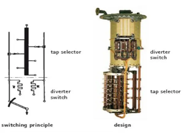
Figure 11: OLTC with both diverter and tap selector
In each phase, there are two moving contacts within the tap selector, one is capable to select
the odds numbers and the other for selecting the even taps numbers as shown above. Since
the tap position numbers must be either odd or even, only one of the moving contacts carries
current at a time, except during tap changer.
Table 1: Transformer data specification
Rated Voltage Ratio 66,000/11,000 V
Rated KVA (ONAN) 10,000 kVA
Insulation Level HV 325 kV
Insulation Level LV 95 kV
Number of phases 3
Frequency (Hz) 50
Vector Symbols Dyn11 or Dyn1*
Winding Terminations – HV & LV Bushing
Earthing on all windings Effectively earthed
[image:27.595.59.536.470.765.2]Page 28 of 91
Protective devices Buchholz – main tank and tap-changer Oil
and winding temperature pressure relief
HV, LV and LV Neutral
Tapping range (% of rated input voltage) -15% (boost), +5% (buck)
With OLTC Taping steps voltage 1.25% of 66kV
Impedance 10 % on 10 MVA base
The transformer vector group can be converted between DYn1 and DYn11 by adjusting links
on the transformer as per requirements.
1.3.4
The 11 kV Plant
1.3.4.1The 11 kV Reclosers
Reclosers are non-air insulated pole mounted switch installed outside of a substation that trip
automatically to clear faults, and then reclose after a predetermined time interval. An 11 kV
recloser is installed on each of the three phase outgoing 11 kV feeders.
Reclosers have current transformers, capacitive voltage transformers (CVT), circuit breaker
mechanisms and lightning arresters/mountings all contained within a fully welded and sealed
stainless steel enclosure. These reclosers have a minimum rated primary current of 800
Amperes and a maximum rated short time current of 12.5 kA. They have the ability to be
connected to the SCADA system for remote operation and integration.
1.4.0
Skid Mounted Substation ancillary components
The 66/11 kV SMS’s components include the following systems: protection, metering,
Page 29 of 91
role in substation design operation. There are other components which are not critical to the
performance of the system but are primarily used for measurement or maintenance functions.
These include monitoring operation of device, switching tools and oil containment apparatus.
1.4.1 Protection system
Protection performance requirements specify the balance between the conflicting goals of
reliability and security. Reliability goals require maximum sensitivity and fast response time
to detect and clear all faults quickly with very low probability of a failure to trip. While
security goals require maximum selectivity and slow response time to minimize the
probability of spurious operation leading to an unwanted trip on a faultless circuit. Security is
very important during normal, fault and faultless conditions. Power system equipment assets
such as generators, busbars, transformers and power lines are monitored by protective relays
designed to detect faults and operate isolating devices designed to interrupt damaging fault
current.
Protective relays analyse the output currents and voltages measured by instrument
transformer on the high-voltage apparatus. For instance, the power transformer is equipped
with differential protection scheme as the main form of protection with instantaneous
over-current and earth fault detection as backup.
The earth fault protection (EFP) function protects mostly the line or any other electrical node
by local zero current measurement or calculation against rapid increasing short circuit current
to ground. The protection earth fault trips if the current flowing in the neutral exceeds some
predetermined level.
Current and voltage signals are monitored to decide whether the protection has to act to
Page 30 of 91
the breaker. However, each level of substation involves several protection relays of different
types and each relay is assigned to manage a specific type of fault.
1.4.2 Communication systems
SCADA communication provides periodic exchange of short data messages between a
central platform in the control centre and the remote terminal units (RTU) in substations. The
messages contain status indications, measurements, commands, set point and synchronizing
signals that can be transmitted in real time and requiring high data integrity, accuracy and
short transfer time. The communication system provides interfacing between the local
substation programmable remote terminal units (RTU) local SCADA and the Network
Control Centre SCADA system. The goal of SCADA communication systems is to control
and monitor the operation of the network.
1.4.3 Skid Mounted Substation control
The skid mounted substation (SMS) has integrated control systems that optimise the
operation of the substation within the electricity distribution network. This is the case for any
control with SCADA point both internal and external to the substation interface that provides
access to substation real time operational data and operational metering data.
1.4.4 Skid Mounted Substation Earthing systems
The earthing system is used to accommodate a skid mounted substation and provide an
earthing system connection to which transformer neutrals or earthing impedances connected
in order to pass the maximum fault current. The earthing system ensured that no thermal or
mechanical damage occurs on the equipment within the substation, thereby resulting in safety
to operation and maintenance personnel. Substation earthing provides a safe return path for
Page 31 of 91
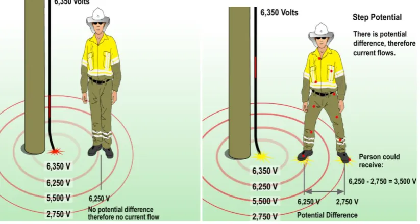
Figure 12: Earth potential (Ergon Energy, 2011)
Substation earthing control earth potential fluctuation step, touch voltages and provide
lightning protection. Touch voltage is the difference in potential between the surface potential
and the potential at earthed equipment whilst a man is standing and touching the earth
structure as shown in figure 13. Step voltage is the potential difference developed when a
man bridges a certain distance with his feet whilst not touching any other earthed equipment.
Page 32 of 91
Figure 13: A typical earth potential variation (Ergon Energy, 2011)
Line arresters are used to reduce the risk of having dangerous touch or step voltages due to
power frequency earth potential rise. If the skid mounted substation is to be deployed on a
green field site, an adequate earth grid must be provided on site prior to installation. The earth
system is designed to ensure that it complies with the standards and safety requirement.
1.4.5 AC/DC Supplies Systems
The SMS has a very reliable three phase four-wire, 415V AC power supply. This supply is
sourced either directly from an 11 kV/433V station service transformer or a 25 kVA auxiliary
winding built into the main power transformer.
The skid mounted substation is equipped with a highly reliable 48 V DC supply for auxiliary
critical systems within the substation. This supply is able to power the critical systems of the
skid mounted substation for a minimum of 10 hours during and after an emergency situation.
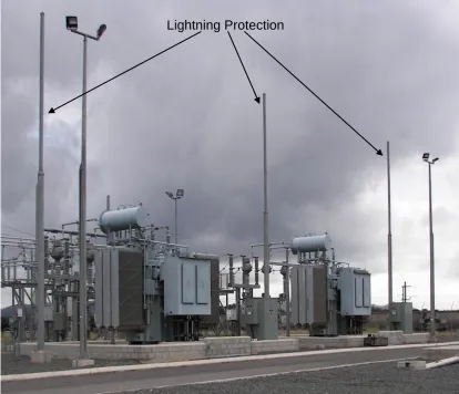
1.4.6 Skid Mounted Substation lightning protection systems
The lightning protection system provides adequate lightning protection for the safety of plant,
Page 33 of 91
calculate the level of protection for a substation. This along with the equipment basic impulse
levels (BIL) and the earth system design form an integral part of the insulation co-ordination
system design of the substation.
Surge diverters are installed on the power transformer primary side of 66 kV circuit breaker,
the 11 kV bus, and the 11 kV reclosers. If the skid mounted substation is to be deployed on a
green field site, adequate lightning protection is provided on site prior to installation s shown
[image:33.595.90.505.298.654.2]in figure 14.
Figure 14: A typical substation lightning protection (Ergon Energy, 2011)
An appropriate lightning protection of substation networks is required to minimize damage to
equipment, power plant and public.
Page 34 of 91
1.4.7 Metering functions
The metering system is installed on 66/11 kV Skid Mounted Substation to provide statistical
or revenue metering information where available. There are two types of energy metering
which include external and internal metering. The external metering represents either the
conventional energy meters external to the substation digital system but feeding it with
energy information through contact pulses or other devices with serial communication. The
internal energy meter calculates the energy from the voltage and current. Metering in this
context includes both measuring for operation purposes and metering for billing.
1.4.8 Skid Mounted Substation Safety
Why do we need to be extra conscious in considering substation safety? Staffs are expected
to visit substation sites for maintenance and other services design requirement. There is a
range of safety policies. The detailed application of these policies to major substation
construction, operation and maintenance is checked as part of the detailed design process. In
particular, all new sites will meet regulatory and Australian Standard requirements for
electrical clearances. Space will be allowed in the substation to carry out maintenance,
replacement of plant and extension of the facility without the need to remove adjacent
equipment from service where ever practicable. Auxiliary systems will be designed with the
safety of operating and maintenance control in mind. Figure 15 shows a burning substation
Page 35 of 91
Figure 15: Burning substation
To maintain reasonable safety procedures, the following are put into consideration to ensure
the safety for plant equipment, environment and the public. Earth potential rise (step and touch potential)
Electromagnetic fields (EMF)
Access – public members must not gain access to substation
Clearance
Fire
Equipment failures – some pieces of plant can fail explosively which may causing
Page 36 of 91
Figure 16: A typical substation clearance and equipment failure (Ergon Energy, 2011)
1.4.8.1Risk associated with Skid Mounted Substation
There are several risk associated with SMS which include but not limited to:
Transformer oil leak
Transformer tank rupture causing possible fire
Major components e.g. CT fail with porcelain rupture, surge arrestors fail with
porcelain rupture
1.4.8.2Control measure
Major component need to be correctly tightened to support frames otherwise
looseness causing conductors to be stressed and made loose.
All connection must be correctly tightened otherwise risk of looseness causing hot
spots
Transformers protection devices e.g. Oil level and winding temperature indicators and
Buchholz relays need to be checked regularly to ensure correct set up and operation to
Page 37 of 91
1.4.9 Environmental safety
Environmental safety is very important. Therefore, the substation is laid out to allow the noise and
EMF levels to be within acceptable levels at the substation boundary. Oil containment is provided for
all transformers with a capacity and the storm water drainage system is designed to allow monitoring
of discharges from site.
To reduce the use of the Greenhouse gases, vacuum-switching technology is used wherever possible.
At voltages above 33 kV where vacuum circuit breakers are not available, the use of SF6 gas is
minimized. In general, SF6 is used when no other economic alternative is available.
1.5.0 Summary
The project is mainly focusing on changes to SCADA communication system that aligned
with IEC 61850 communication standards protocols. The existing 66/11 kV SMS design has
outdoor 66 kV Circuit Breaker that need to be dismantled to relocate. Therefore, the primary
focus of the new design project is to eliminate this and find room within the SMS to
accommodate the Gas Insulated Switchgear (GIS). In doing this, the system will be
connected to the network much quicker and more readily transportable as a fully assemble
SMS.
Page 38 of 91
Chapter
2
New Improved 66/11 kV Skid Mounted Substation
2.1. Introduction
Industry Standards which govern the design, testing and application of power devices and
communication interfaces have undergone significance changes since their original
publication. This revolution of standards follows changes in both advancing technology of
equipment and increasing demands imposed on them due to the complex environment which
they are applied. This ever-ending technology development makes it critical for engineers to
be aware of the current status of, and recent changes to these standards in order to properly
specify and applied the equipment.
This section will begin with a theory of circuit breakers, describing method used and any
significant changes made or used currently. Described and show the method of operation of
various technologies of interrupters that have been and currently being used in medium and
high voltage circuit breakers. Provides comparative information to help understand the GIS
Page 39 of 91 2.1.1 Circuit breaker theory
Circuit breakers (CB) are breaking devices designed to open and close a circuit by
non-automatic means and to open the circuit non-automatically on a predetermined overcurrent
without damage to itself when properly applied within it rating.
A circuit breaker must be able to be switched open and closed manually and to protect a
circuit from overcurrent by opening automatically. This allows a breaker to be used
repeatedly without replacement.
The switching function of CB provides easy isolation for the circuit or circuits protected by
the circuit breaker from the rest of the electrical system, allowing safe modification or
maintenance of the equipment in the circuit. All CBs are intended to switch load and some
are specifically rated for switching load such as lighting in commercial and in industrial
buildings on a regular basis.
2.1.2 Gas Insulated Switchgear (GIS)
Gas Insulated Switchgear is metal-enclosed switchgear in which the insulating medium is SF6
at higher than atmospheric pressure. GIS technology is typically of modular design and filled
with a minimum quantity of SF6. It has low life cycle cost compare to air insulating
Page 40 of 91
Figure 18: A typical GIS switchgear
2.1.3 Circuit breaker technology
The SF6 circuit breakers are based on SF6 puffer principle used in Gas Insulated Switchgear
(GIS) applications. SF6 puffer circuit breakers have good interruption capabilities and are
particularly well suited to application in a GIS environment that also uses SF6 for the main
dielectric medium.
The downside with SF6 puffer circuit breakers is the relatively high driven energy
requirement. The flow of high pressure gas necessary to travel along over the length of the
arc drawn between the contacts is generated by the mechanical compression of SF6 gas in the
puffer interrupter cylinder. The energy requirement for this operation can be considerable and
additionally a high energy mechanism leads to high reaction forces on the GIS support
framework and foundations.
The advantage is using the interruption methods such as thermal, auto-expansion or self-blast
interrupters that requires less energy. These methods can overcome high operational energy
Page 41 of 91
The existing 66kV outdoor circuit breaker requires dismantling for relocation. This is to be
eliminated by changing the type of CB and making a room to accommodate it. The more
compact the switchgear is, the less space it occupies, there is a chance that the installation
will fit within the available space and be more readily transportable. Figure 19 shows typical
containerized indoor gas insulated switchgear (GIS).
[image:41.595.62.535.227.494.2]
Figure 19: 66kV (GIS) Gas Insulated Switchgear (Ergon Energy, 2011)
2.1.4 Gas insulated switchgear transport design
The best scenario is the installation of the switchgear module within a container for easy
transportation regardless of whether it is used as a moveable or stationary on the Skid
Mounted Substation. GIS is disassembled for packing and shipment. The equipment is
designed to minimize the number of disassembled parts, while considering performance,
maintenance, ease of installation and transportation. The disassembled parts are packed as a
Page 42 of 91
2.1.5 Indoor Gas Insulated Switchgear (GIS)
The main role of buildings indoor GIS switchgear installations is to house all primary and
secondary equipment. Indoor GIS design in particular, requires specials measures against
dust penetration GIS room, SF6 ventilation system and direct connection of switchgear
earthing grid with the building reinforcement.
As the volume of the container is limited it can be used for full GIS only for rated voltages up
to 245kV or very small switchgear. Relocatable equipment is considered as GIS of variable
layout which can be moved to new locations of use and service with little dismantling,
[image:42.595.75.482.345.620.2]assembly and commissioning effort.
Figure 20: A typical GIS switchgear (Ergon Energy, 2011)
Moveable GIS are needed for temporary distribution of energy in cases when the planning
Page 43 of 91
temporary means of supply during network upgrading, for rebuilding of substations or
increasing load demand.
2.1.6 GIS hazards and safety
Like most fire protection systems, which are based on minimizing the hazards for the
operators, public, environment protection and assets by limiting damage to power
transformers and to adjacent apparatus, equipment, buildings and other single elements and
minimizing the outage of power to the customer.
Sulphur Hexafluoride (SF6) is a relatively non-toxic gas but is a greenhouse gas. The good
dielectric and other physical properties have led to the extensive use of SF6 as an insulating
medium in switching equipment such as circuit breakers. While SF6 is inert during normal
use, toxic by-products can be produced that pose a threat to health of workers who come into
contact with them. The side-effect includes long term respiratory damage, skin irritations and
acidic burn damage.
An indoor GIS installation does not require any specific fire precautions except for special
interface applications such as oil or cable terminations. No pressurised porcelain or other
potential risk of explosion due to failure of insulation is involved.
With the use of SF6 insulation risk of oil or fire can be eliminated. In general and
independently, indoor installation requires more considerations than outdoor installations.
The following has been considered in the design:
1. Appropriate material for walls
2. Ceilings
3. Fire barriers
4. Escape routes
Page 44 of 91
6. Emergency exits
2.1.7 Security of GIS
Gas Insulated Switchgear (GIS) is inherently suited to provide high levels of security due to
increased reliability and availability compared to other technologies such as Air Insulated
Switchgear (AIS) and other solutions which result in increased levels of availability of power
supplies. All conductors in GIS are enclosed in earthed metal enclosures which make it
impossible for casual intruders to accidentally come into contact with high voltage
connections. This means that the risk of accidental electric shock during sites visit is
eliminated compared to conventional switchgear design.
2.1.8 GIS impact on environment
Transports are considered as a big contributor to the negative environmental influence. The
disconnecting circuit breaker system will off course reduce that part as the less use of
material and the decreased number of apparatus implies less transports. Sulphur hexafluoride
gas (SF6) is a gas with outstanding isolating and extinguishing qualities and is for the time
being the only technical and commercial alternative for high voltage (HV) circuit breakers
(CBs). However, SF6 has the drawback that it contributes to the greenhouse effect and must
therefore be handled with caution. For this reason, the used amount must be kept as low as
possible and that is the case of Skid Mounted Substation design.
Containerized switchgear solutions used special indoor applications but are protected from
some of the environmental factors such as rain, wind, strong solar radiation and extreme
pollution. The type shown in figure 21 is solidly constructed for transportation and this helps
Page 45 of 91
Although the total length of SF6 seals is the greatest within GIS, consideration should be
given to the fact that GIS equipment can be installed indoor, thus minimizing exposure to
environment and extending the life of the sealing systems.
GIS produce lower levels of noise due to the fact that equipment is completely enclosed, and
[image:45.595.94.483.241.488.2]the SF6 gas in the enclosures is a very efficient sound absorber.
Figure 21: A relocatable GIS switchgear (Ergon Energy, 2011)
However, every action should be taken to keep the level of SF6 emission to minimum, since
the amount of SF6 within the substation become larger as a result of gas insulated technology
developed.
2.1.9 Future possibilities
Sulphur hexafluoride gas SF6 circuit breakers have better maintenance and failure
performance than disconnected switches. That means that the traditional way of (isolating
Page 46 of 91
systems and disconnected switches rather decrease the availability than increase it. In this
case, the best way to increase the availability is to avoid using disconnected switches and use
circuit breakers (CBs). However, due to safety aspects a disconnected function is necessary.
In a disconnecting circuit breaker, disconnection function is integrated in the circuit breaker
and it is then possible to design disconnected switches free substation solutions.
2.2 Conclusion
The requirement to change type of circuit breaker has been reflected in the associated gas
insulated switchgear (GIS) equipment. As mentioned earlier, the 66kV outdoor type circuit
breaker will be replaced by modern SF6 circuit breaker. This will eliminate the dismantling
Page 47 of 91
Chapter 3
3.1. Introduction
This section will look at current situation and outline the development of communication in
SCADA systems between control centres and Remote Terminal Units (RTU). Investigate the
possibility of integrating SCADA communication with IEC standards protocols.
This has been achieved by presenting a series of real service providers which explained the
future and transition from today’s situation to the future one. The outcomes will determine
the recommendation for future improvement for the systems design.
3.1.1 Supervisory Control and Data Acquisition (SCADA)
Supervisory Control and Data Acquisition (SCADA) is the central system that provides full
remote control and monitoring of the system. It has been in service for many years in power
utilities for operation and control of electrical systems. SCADA systems typically use low
speed (200 to 1200 bits per second), Point to point, point to multipoint or ring simple and
dedicated network structures. It provides support interfacing between the local substation
programmable remote terminal unit (RTU) and the network control centre SCADA system.
A SCADA system covers most functions necessary to monitor and control the operation of
Page 48 of 91
Control Centres are required to exchange information with generating stations, substations
and other Control Centres. The information to be exchanged comprise real time and historical
power system monitoring data including control and accounting data. Figure 21 shows typical
[image:48.595.145.482.249.529.2]control centre transported using router network.
Figure 22: Typical control centre transport using router network (CIGRE, 2000)
Most power system architecture and their operational organization often include different
hierarchical levels of Control Centres as well as geographically distinct back-up facilities.
3.1.2 Data Type
There are three sets of standards that are more applicable in different contexts of
Page 49 of 91
1. Semi-static Data
2. Real Time Data
3. Historical Data
The Semi-static data is suited to communication between control centres. It describes the
physical processes such as power system topology, functions such as asset parameters and
displays.
Real time data from the physical process involve features such as alarm, event, and status,
analogue measures of energy generation, load flow, voltage and current. In addition, real time
data may be imported from other information system such as SCADA nodes from external
SCADA systems.
Historical data has long term storage of selective real time data for trending, analysis and
planning purposes.
This dissertation describes the alternatives, takes a look at different approaches used or
planned by power utilities and highlights the number of difficulties using three
aforementioned sets of standards and draws a conclusion depending on the outcomes of the
investigation.
3.1.3 Data communication
Due to ever changing world of communication technologies, the need for higher availability
and faster information for data communication requirement is rapidly changing. Mostly
digital network communication systems are being installed for internal and external use by
communication services providers. This section focuses on data communication network
used:
Page 50 of 91
2. Centre-Centre and information exchange with other companies
3. Information access to mailboxes, info centres (Meteorology, Energy Stock Exchange)
4. Utility-wide office information (mail, maintenance, service, data exchange with
corporate database, video)
5. Telephone and facsimile services
The abovementioned types of data communication have different requirements when it comes
to:
1. Communication path
2. Speed transmission
3. Data volume
4. Quality (security, availability, reliability)
5. Transmission protocols
6. Interfaces to the network
7. EMC compatibility (especially within substations)
8. Integrity of data and mobility
In addition, the data communication requirements are affected by the Internet technology
strategies and IT development for electricity service providers. This widespread availability
of the internet technology may possibly affect future requirements of data communications if
appropriate control measures are not implemented. Table 2 gives an overview of the different
Page 51 of 91
Table 2: Service provider data communication requirements
Requirement
Type of data communication Interface Com path Transmissi on speed kbit/s Data volume Quality availability Transmission protocol Application protocol Special remarks
A Power network control and monitoring
A1
SCADA (supervisory control and data acquisition)
G.703, X.21, V.11, V.24
PDH 0.3-64 Small,
sporadic or cyclic
High 99.95–99.9%
IEC 60870-5-101
IEC60870-5-101
A2
LFC (load and frequency control)
G.703 ,X.21, V.11, V.24
PDH 0.3-64 Cyclic, permanent
High, 99.99% IEC60870-5-101
IEC60870-5-101
A3
Energy metering
G.703, X.21, V.11, V.24
PDH 0.3-64 0.5-10Kb periodic
High, 99.00% IEC60870-5-102
IEC60870-5-102
A4
Video for plant supervision
G.703 PDH 2 x 64 Medium,
permanent
Low. 99.99-99.5%
Proprietary
A5
Remote access for control and monitoring
Modem, 33.36kbit/s or 64kbit/s ISDN
Switched network
1.2-64 Small, as needed for services purpose
High, 99.95% Often proprietary
A6
Meteorological data acquisition
G.703, X.21, V.11, V.24
PDH or Switched network
1.2-64 Small, permanent
High, 99.00% n/a
A7
Line protection equipment
G.703, X.21, V.11, V.24
PDH 0.3–64 Small,
sporadic
High, 99.99% IEC60870-5-103
IEC60870-5-103
B
Centre to centre and information with other utilities
Router LAN Ethernet, TCP/IP to Frame – Relay G.703 or later ATM/SDH
PDH, or later ATM/SDH ISDN as a backup
2 x 64, may be increase if necessary
Medium, burst some kB to MB
High, 99.9 – 99.99%
depending on the application TCP-IP Frame-Relay encapsulation TASE.2 ELCOM 90 C
Page 52 of 91
C1
Access to data bases of general interest
Router LAN Ethernet, TCP-IP to ISDN
ISDN or analogue modem
64 or
33.6/56
Medium to very high: some kB to many hundreds MB
Medium to high, 99.0-99.90%
TCP-IP
C2
Access to manufacturer’s data base
C3
Access to external e-mail services
C4
Access to utility’s home page
C5
Access to meteo services
D Utility wide office information D1
Access to utility’s internet e-mail
Router LAN, Ethernet, TCP-IP to Frame Relay or eventually PC communication over modem
PDH or ISDN backup
64 Some kB High, 99.90% TCP-IP alone or with Frame-Relay
D2
Access to utility’s services (WAN, LAN) computer-computer link
PC: 1 to 2 x 64 other: n x 64
kB to MB Depend on the application
D3 Video for plant supervision PDH 2 x 64 ~12kBytes/ s
High, 99.95% Proprietary
D4
Access to utility’s meteo service
PDH 2 x 64 ~12kBytes/ s
High, 99.90% Replaced by F2
D5
Access to energy exchange planning
PDH or ISDN backup
1 to 2 x 64 Some kB High, 99.95% Frame-Relay
Page 53 of 91
E1
Red line phone (***)
Analogue 3.1 kHz
PDH 64 n/a Low, 99.99% A-law
E2
Utility’s phone (***)
Low, 99.90%
E3
Normal phone (***)
Analogue 3.1 kHz or ISDN
Analogue or ISDN
Analogue or 64
Analogue or A-law
E4
Transmission network’s service phone (***)
PDH 64 Low, 99.95% a-law
E5
Facsimile
Analogue or ISDN
Analogue 14.4; ISDN 64
Some hundred kB
High, 99.90% ITU…
F
Videoconferencing/videophone
Page 54 of 91
F1
Videoconferencing
G.703, X.21, ISDN
ISDN or PDH
n x 64 Some hundred MB
High, 99.90% ITU H.320 H.323 Frame structure H.261, H.263, data
transmission T.120
PABX own
F2
Videophone over internet (****)
Modem analogue or ISDN
Analo gue or ISDN 33.6/56 /64 Some ten MB High, 99.90 % H.323/ TCP-IP
PABX and Internet provider
H.323 supporting following voice compression algorithms: G.711/G.723.1/G.728/G.729/G.729A for respectively 64/6.3/16/8/8kbit/s
G Data (or phone) over satellite VSAT (propagation delay =~253ms*** V.24, x.25 Satellit e Mainly up to 9.6 seldom 32 or 64 Small to mediu m Mediu m, 99.0% or higher Veterby FEC ½, BPSK
Page 55 of 91
As shown above in table 2, it is clear that the type of data communication used by power
network for control and monitoring is the plesiochronous digital hierarchy (PDH).
3.1.4 Communication network
The communication used by most utilities today typically consists of:
1. Mesh microwave radio link
2. Copper cable (4-wire and coax)
3. Power line carrier Digital or analogue
4. Integrated Service Digital Network (ISDN) connection for backup transmission
5. Meshed optical fibre network
3.1.5 Impact of deregulation
The current deregulation in telecommunications as well as in the electricity power industries
and distribution sectors exerts a massive influence on the internal communications between
the electricity supply undertakings. In some cases it brings forth absolutely contradictory
trends and requirements.
3.1.6 Competition
Deregulation of the utilities has resulted in increased competition. The margins on energy
prices is more likely to drop as a result, the utilities are more likely to consider the cost more
carefully and built their network to be more affordable and reliable. This may lead the
transmission network to be used for the power generation and the commercial services which
may be reliable. Basically, the same data can be declared important or less important
Page 56 of 91
exists. The use of open systems and equipment complying with international standards
guarantees the protection of the investments.
3.1.7 Technical development and influence on the data transfer
In order to reduce the load both in the transmission network and at the control centre, more
local intelligence may be delegated to remote stations. For example the plausibility of the
meter values may be checked locally instead of sending the values of both the main and the
check meter to a control centre. This may reduce the quantity of data, but the use of standard
transfer protocol IEC 60870-5-101 for SCADA applications, which are often less efficient
than the previous optimised proprietary protocols, will increase the number of bits to be
transmitted, so that the need for transmission capacity will increase rather than decline.
Low speed data transmission between the control centres and remote stations may be
replaced by a transmission produced by remote database access at higher bit rates either at
control centre or at remote stations. For the database access between control centres,
frame-relay or similar protocols providing similar functionality are recommended to enable sharing
the available transmission capacity with many users.
3.1.8 New technologies
Internet brings access to databases of general interest, gives the opportunity to download new
software updates and offers an efficient e-mail service. However, the transmission of data
over the internet is not very secure, the data can be read and modified by unknown third
parties and the effective data through bit rate depends on the network load. Anti-viruses
Page 57 of 91
3.1.9 Satellite (VSAT)
Satellite transmission is usable for sites not easily accessible with traditional transmission
lines. Very small aperture terminals (VSAT) transmit at low bit rates of 300 to 9600bit/s at
low cost. A link availability of 99.0 % or higher (refer to table 2) can be guaranteed. If some
information is needed at many sites in a secure way, a broadcast transmission procedure is
not suitable. The best suggestion way is to consider sending the information first to hub. This
hub forward the information to one remote station after the other in such a way the
transmission quality can be individually checked.
3.2. Synchronous digital hierarchy (SDH)
The very high transmission capacity offered by Synchronous Digital Hierarchy (SDH)
systems is not strictly necessary for the stand-alone utilities in the near future. SDH is already
replacing plesiochronous digital hierarchy (PDH) for bit rates higher than 34 Mbit/s and is no
longer more expensive than PDH. It is also predicted that the availability of PDH equipment
will be phased out by the major manufacturers in the short term as the demand decreases.
Very few public telecommunications operators are ordering PDH equipment currently and
manufacturers tend to concentrate on the requirements of the public operators. Due to large
quantity of data transmitted, it is not possible to buffer them into the transmission equipment
as is commonly done when using the PDH technique. This means every switching operation
between the main transmission path and the auxiliary transmission path may lead to an
interruption of the link for some milliseconds depending on the reaction time of the
equipment and data will be lost. Data integrity should be ensured by using an appropriate
Page 58 of 91
3.2.1 Integrated services digital network (ISDN) for backup
The integrated services digital network is a low-cost solution for backup lines. Due to the
dial-in time of up to 2 seconds it is not usable for the transmission of line protection signals.
It is also subject to congestion at peak traffic hours after a disruption or when the
telecommunication service providers’ interruption.
3.2.2 Future development
It becomes more and more necessary to guarantee the interoperability of the systems used in
the private network with those used in the shared sectors. The equipment used must be
compatible with a system many neighbouring utilities can agree upon. The control centre
systems must enable remote database access, using relational databases.
3.2.2.1 Communication
The availability of transmission of communication data over optical fibre can possibly
replace the existing analogue transmission systems over private copper cables, rented lines
and also some analogue Power Line Carrier.
The network structure used for communication between control centres and remote stations
will still remain in many places as a logical star network for economic reasons, and as far as
possible, a physical ring or a meshed network.
3.2.2.2 Network hierarchy
There are two options availabl