Theses Thesis/Dissertation Collections
2009
Inside all-optical networks
Sana Tariq
Follow this and additional works at:http://scholarworks.rit.edu/theses
This Thesis is brought to you for free and open access by the Thesis/Dissertation Collections at RIT Scholar Works. It has been accepted for inclusion in Theses by an authorized administrator of RIT Scholar Works. For more information, please [email protected].
Recommended Citation
Rochester Institute of Technology (RIT)
College of Applied Science & Technology (CAST)
Electrical Computer and Telecommunications Engineering Technology
(ECTET)
Inside All-Optical Networks
By Sana Tariq
A Research Thesis Submitted in Partial Fulfillment of the Requirements
for the degree of
Masters of Science in Telecommunications Engineering Technology
(MSTET)
Course Advisor
Prof. Warren L.G. Koontz Professor and Program Chair
Telecommunications Engineering Technology College of Applied Science & Technology
Committee Members
Prof. Ronald Fulle Prof. Mark Indelicato
Scope of Document
This document is submitted as a graduate thesis for the MS in Telecommunications
Engineering Technology (MSTET) at Rochester Institute of Technology (RIT). The intended
audience of this document is the faculty and students of the department of Electrical,
Computer and Telecommunications Engineering Technology (ECTET) at the College of
Preface
In fall 2007, I joined Rochester Institute of Technology (RIT), for the MS Program in
Telecommunications Engineering Technology under a Fulbright scholarship. While working
with Prof. Warren Koontz in fiber optics courses and Prof Ronald Fulle, I was exposed to
cutting-edge technologies of telecommunications. I became extremely inspired by optical
communication technologies and its revolutions in telecommunications industry.
Optics will change the face of the telecom market over the next few decades. During a case
study in the course of next generation networks, I realized through my research that by the
year 2020 more than 80% of copper cables in the world would be replaced by high capacity
fiber optics.
My inspiration to optics and my passion to learn more about it led me to apply for a Fulbright
scholarship for doctorate-level research. I received this prestigious award once again for
conducting Ph.D. work in optical communication. I was accepted at two of the best Optics
Schools in the US, CREOL at the University of Central Florida and College of Optics at
University of Arizona. I have also been offered university graduate scholarships and
fellowships in admission offers from these prestigious schools. I will start my Ph.D. in Optics
this fall at UCF.
I wanted to choose a topic for my thesis that could employ my knowledge of networking and
years. I also wanted to explore optical communication in further depth as that would set the
stage for my future roadmap. I chose to work on all-optical networks, which is the next
biggest breakthrough in telecom infrastructure and IP and which has already changed the
Acknowledgements
I want to express my heartfelt gratitude to all those whose support and honest contributions
helped me complete this work.
First of all, I want to thank God Almighty for showering His unlimited blessings on me
throughout my life. I attribute all my success to God Almighty, Whose love and help in my
endeavors have always bore fruit.
My sincere thanks go to RIT ECTET department for providing all the support and resources
required to complete this work.
It gives me a great pleasure to express my earnest gratitude to my thesis advisor, Prof.
Warren L.G Koontz, Program Chair – TET and my course advisor. His always understanding
and always supporting attitude helped me achieve my ambitious academic objectives with a
relaxed mind. He helped me exploit my full potential for my work without being worn out. He
allowed me to follow my interests and guided and supported me in every way possible. He has
always been a constant source of energy to his students.
I want to pay special thanks to Prof. Ronald Fulle whose inspiration, vigor and confidence
motivated me to do something special in life. It is through his confidence and trust in my abilities
that I am able to bring out my best. I thank him once again for helping Prof. Koontz in giving me
online access to Opnet Transport Planner, which brought the final touch to my long and tiring
I want to thank all the faculty members of ECTET and NSSA with whom I took courses on
telecommunications and Networking that formed the foundation for my thesis. Prof. Mark
Indelicato, Prof. Charles Border and Prof. Shenoy helped me achieve crystal clear concepts on
tough subjects that helped me with my thesis and will continue to stay with me in my future
endeavors.
I also want to express my sincere gratitude to my course advisor, Sydney Seaver whose help and
support sailed me through in every difficult situation; from course work to thesis completion and
beyond.
It would not be an exaggeration if I attribute a greater part of my success and fulfillment in life to
my husband Saad Arif. My thesis could not have been completed without the support and
encouragement he offered me throughout. I owe special thanks to my loving and supporting
parents and family, who brought me where I am today; they always took pride in my
accomplishments. I want to thank God for blessing me with an angel baby girl Irsa, who gave me
a new bearing in life and helped me appreciate its beauty and exquisiteness in a new sense.
Problem Statement
This thesis will to explore various aspects of all-optical networks and prove that All Optical
Networks (AONs) perform better than electro-optical networks. Performance analysis of
electro-optical and all-optical networks will include node utilization, link utilization and
percentage of traffic routed under various conditions of traffic load on the network.
Abstract
Imagine a world where lightning speed Internet is as common as telephones today. Imagine
when light, the fastest moving thing in the universe, is the signal-carrying transport medium.
Imagine when bandwidth no more remains a constraint for any application. Imagine when
imagination is the only limit! This all can be made possible with only one technology and
that is optical communication. Optical networks have thus far provided a realization to a
greater extent to the unlimited bandwidth dreams of this era, but as the demands are
increasing, the electro-optic conversions seem to become bottlenecks in blended optical
networks. The only answer to this is a complete migration to „All-Optical Networks‟ (AONs)
which promise an end-to-end optical transmission.
This thesis will investigate various aspects of all-optical networks and prove that AONs
perform better than currently existing electro-optical networks. In today‟s‟ electro-optical
electro-optical and all-optical networks would include node utilization, link utilization and
percentage of traffic routed. It will be shown through Opnet Transport Planner simulations
that AONs work better under various traffic conditions.
The coming decade will see a great boom in demands on telecommunications networks. The
development in bandwidth-hungry applications like real-time video transmission,
telemedicine, distance learning and video on demand require both an unlimited amount of
bandwidth and dependable QoS. It is well understood that electrically switched networks and
copper cables will not be able to meet the future network demands effectively. The world has
already agreed to move towards optical communication techniques through the introduction
of fiber in access parts of the networks replacing copper. Now the race is to bring optics in
higher layers of OSI reference model. Optical communication is on the horizon, and new
discoveries are still underway to add to the value of available bandwidth through this
technology.
My research thesis will primarily focus on the design, architecture and network properties of
AONs and challenges being faced by AONs in commercial deployment. Optical components
required in AONs will be explored. A comparison between AONs and electro-optical
networks will also be shown through optical transport planner simulations.
Key words: All-Optical Networks, IP, Protocols, Optical Transport Planner, Optical
Introduction
This document is presented as a detailed thesis on all-optical networks. It is broken down into
chapters, each chapter highlighting different aspects of these networks. Below we provide a
brief overview of how this document is organized.
Chapter 1 begins with the introduction of optics. The past, present and future role of optics in
telecommunications industry is discussed. Optics is gaining importance in various research
areas due to a number of applications in military, medicine, industry, space explorations and
telecommunications. The use of optics in telecommunications is the main focus of this thesis.
Chapter 2 discusses the reasons for migration towards all-optical networks. Since the Internet
is becoming the center of future services, it would require a much larger bandwidth that is
only possible by completely avoiding electronic bottlenecks throughout the network. Various
advanced concepts are also presented. The promise of a bandwidth satisfying future demands
is enough to bring the technology from research test bed to the market.
In chapter 3, we have presented the evolution process of all-optical networks.
Telecommunication networks went through various transitions and constantly evolved to
meet bandwidth demands as applications and services developed. We have presented three
generations of network evolution. Chapter 4 discusses the invention of those devices that
paved the way to all-optical networks. These include devices involved in optical signal
responsible for end-to-end transmission of optical signals (like optical fibers, amplifiers and
couplers) and the devices that are responsible for routing these signals to the correct path
(optical switches and routers).
Chapter 5 discusses various multiplexing techniques that are employed in all-optical
networks. In this section, we discussed three popular types namely optical time division
multiplexing (OTDM), code division multiple access (CDMA) and wavelength division
multiplexing (WDM).
Chapter 6 is about various architectural forms of WDM networks, their advantages and
disadvantages and their implementation limitations. In chapter 7, we have discussed the most
commonly categorized types of all-optical networks. Chapter 8 begins with a discussion on
importance of IP in today‟s communications world and it then presents the idea of having the
strengths of IP world combined with those of all-optical networks. In chapter 9, overall
network architecture of WDM optical networks is explained. The relation of optical network
layers with OSI reference model is highlighted.
Chapter 10 discusses project Flamingo, which is one of the current projects on all-optical
networks. We have provided a brief design and architecture of this project. In chapter 11, we
have discussed the routing in all-optical networks. We have presented a few important
protocols in reference to optical domain and their possible extensions. Chapter 12 is about the
challenges being faced in the process of implementation of all-optical networks. We have
Chapter 13 involves the implementation of WDM networks on OPNET Transport Planner.
We have provided a comparison between all-optical networks and networks that have
electro-optical conversions and concluded that all-electro-optical networks are the favorite choice of the
List of Acronyms
AON All-Optical Networks
AP Access Points
ATM Asynchronous Transfer Mode
BER Bit Error Rate
CDMA Code Division Multiple Access
DWDM Dense Wavelength Division Multiplexing
EDFA Erbium Doped Fiber Amplifier EMI Electro Magnetic Interference
FTTH Fiber to the Home FTTC Fiber to the Curb FTTP Fiber to the Premises
IETF Internet Engineering Task Force IP Internet Protocol
IS-IS Intermediate Systems Intermediate Systems ITU International Telecommunication Union LED Light Emitting Diode
OOO Optical-Optical-Optical
OSI Open Standard Interface OSPF Open Shortest Path First OXC Optical Cross-Connect
PON Passive Optical Network QoS Quality of Service
RIP Routing Information Protocol RWA Routing Wavelength Assignment
SDU Service Data Units
TCP Transmission Control Protocol TON Transparent Optical Network
UDP Universal Datagram Protocol WDM Wavelength Division Multiplexing
WIXC Wavelength Interchange Cross-Connect WRN Wavelength Routed Network
Table of Contents
LIST OF FIGURES _________________________________________________________________________ 14
LIST OF EQUATIONS ______________________________________________________________________ 14
OPTICS: A BRIEF HISTORY _________________________________________________________________ 14
INTRODUCTION __________________________________________________________________________ 14 PAST:OPTICS IN TELECOMMUNICATIONS_________________________________________________________ 14
PRESENT:OPTICS IN TELECOMMUNICATIONS ______________________________________________________ 14 FUTURE:OPTICS IN TELECOMMUNICATIONS _______________________________________________________ 14
CONCLUSION ___________________________________________________________________________ 14
DRIVERS FOR ALL-OPTICAL NETWORKS ______________________________________________________ 14
INTRODUCTION __________________________________________________________________________ 14
USE OF INTERNET ________________________________________________________________________ 14
GRAPHICS AND 3D ENVIRONMENT _____________________________________________________________ 14 ONLINE MEDICAL CARE (TELE-MEDICINE) ________________________________________________________ 14 BUSINESS VIDEO CONFERENCING ______________________________________________________________ 14 REMOTE ASSISTANCE ______________________________________________________________________ 14 TRIPLE PLAY AND FUTURE HOME SERVICES ________________________________________________________ 14
CONCLUSION ___________________________________________________________________________ 14 AON EVOLUTION ________________________________________________________________________ 14
INTRODUCTION __________________________________________________________________________ 14 TELECOMMUNICATIONS NETWORK EVOLUTION ____________________________________________________ 14
CONCLUSION ___________________________________________________________________________ 14
OPTICAL COMPONENTS LEADING TO AONS ___________________________________________________ 14
INTRODUCTION __________________________________________________________________________ 14 LIGHT SOURCES _________________________________________________________________________ 14
OPTICAL FIBER __________________________________________________________________________ 14
Single-Mode Vs Multimode Fiber _______________________________________________________ 14
ALL-OPTICAL WIDE-BAND AMPLIFIERS __________________________________________________________ 14
Semi-conductor Laser Amplifier ________________________________________________________ 14
Doped Fiber Amplifier ________________________________________________________________ 14
OPTICAL COUPLERS _______________________________________________________________________ 14 TUNABLE LASERS (TRANSMITTERS) _____________________________________________________________ 14 TUNABLE FILTERS (RECEIVERS) ________________________________________________________________ 14
OPTICAL SWITCHING ______________________________________________________________________ 14 Relational Switches __________________________________________________________________ 14
Logic Switches ______________________________________________________________________ 14
WAVELENGTH CONVERSION _________________________________________________________________ 15
CONCLUSION ___________________________________________________________________________ 15 MULTIPLEXING TECHNIQUES IN AONS _______________________________________________________ 15
INTRODUCTION __________________________________________________________________________ 15 OTDM–OPTICAL TIME DIVISION MULTIPLEXING __________________________________________________ 15 CDM–CODE DIVISION MULTIPLEXING _________________________________________________________ 15
WDM–WAVELENGTH DIVISION MULTIPLEXING ___________________________________________________ 15 CONCLUSION ___________________________________________________________________________ 15 ARCHITECTURAL FORMS OF WDM NETWORKS ________________________________________________ 15
INTRODUCTION __________________________________________________________________________ 15
WDMLINKS ___________________________________________________________________________ 15 PASSIVE OPTICAL NETWORKS (PON) ___________________________________________________________ 15
BROADCAST AND SELECT NETWORK ____________________________________________________________ 15
Physical topologies in Broadcast and select network ________________________________________ 15
WDM broadcast and select network advantages/disadvantages ______________________________ 15
WAVELENGTH ROUTING WDMNETWORKS ______________________________________________________ 15
WRN-Fiber Cross Connect _____________________________________________________________ 15
WRN-Add drop Multiplexers ___________________________________________________________ 15
WRN-Static wavelength router _________________________________________________________ 15
WRN-Reconfigurable wavelength router _________________________________________________ 15
CONCLUSION ___________________________________________________________________________ 15
TYPES OF ALL-OPTICAL NETWORKS __________________________________________________________ 15
INTRODUCTION __________________________________________________________________________ 15 PASSIVE OPTICAL NETWORKS (PONS) __________________________________________________________ 15
TRANSPARENT OPTICAL NETWORKS (TONS) ______________________________________________________ 15
ULTRA-HIGH SPEED OPTICAL NETWORKS: ________________________________________________________ 15
CONCLUSION ___________________________________________________________________________ 15
IP OVER ALL OPTICAL NETWORK ____________________________________________________________ 15
INTRODUCTION __________________________________________________________________________ 15
IP IN TODAY’S COMMUNICATIONS _____________________________________________________________ 15 IP AND OPTICAL COMMUNICATIONS ____________________________________________________________ 15
CONCLUSION ___________________________________________________________________________ 15
OVERALL NETWORK ARCHITECTURE OF AONS _________________________________________________ 15
INTRODUCTION __________________________________________________________________________ 15 OPTICAL LAYER IN OSI REFERENCE MODEL ________________________________________________________ 15
SUB-LAYERS OF OPTICAL LAYER _______________________________________________________________ 15 GENERIC ARCHITECTURE OF OPTICAL WDM NETWORK _______________________________________________ 15
ALL-OPTICAL NETWORK: PROJECT FLAMINGO _________________________________________________ 16
INTRODUCTION __________________________________________________________________________ 16
FLAMINGO’S SCOPE _______________________________________________________________________ 16
FLAMINGO’S ALL-OPTICAL NETWORK____________________________________________________________ 16 CONCLUSION ___________________________________________________________________________ 16
ROUTING IN ALL-OPTICAL NETWORKS _______________________________________________________ 16
INTRODUCTION __________________________________________________________________________ 16 ROUTING IN OPTICAL NETWORKS ______________________________________________________________ 16
ROUTING INFORMATION PROTOCOL (RIP) ________________________________________________________ 16 INTERMEDIATE SYSTEMS-INTERMEDIATE SYSTEMS (IS-IS) ______________________________________________ 16
OPEN SHORTEST PATH FIRST (OSPF) ___________________________________________________________ 16 CONCLUSION ___________________________________________________________________________ 16 CHALLENGES FACED IN DEPLOYING AONS ____________________________________________________ 16
INTRODUCTION __________________________________________________________________________ 16
ROUTING AND WAVELENGTH ASSIGNMENT _______________________________________________________ 16
Static Vs Dynamic Traffic Demand ______________________________________________________ 16
Centralized Vs Distributed Control ______________________________________________________ 16
Wavelength Convertible Networks ______________________________________________________ 16
LACK OF SWITCHING/ROUTING EQUIPMENT_______________________________________________________ 16 HIGH CAPEX FOR AONS ___________________________________________________________________ 16
LACK OF NETWORK INTELLIGENT TOOLS _________________________________________________________ 16 LACK OF TRAINED PROFESSIONALS _____________________________________________________________ 16 CONCLUSION ___________________________________________________________________________ 16
OPTICAL TRANSPORT PLANNER SIMULATIONS ________________________________________________ 16
INTRODUCTION __________________________________________________________________________ 16
DESIGNING A NETWORK BASED ON FLAMINGO MODEL _______________________________________________ 16 PERFORMANCE COMPARISON:OOOVS OEONETWORKS _____________________________________________ 16 IMPACT OF INCREASING NUMBER OF WDM WAVELENGTHS ____________________________________________ 16 CONCLUSION ___________________________________________________________________________ 16 CONCLUSION ___________________________________________________________________________ 16
REFERENCES ____________________________________________________________________________ 16
APPENDIX A ____________________________________________________________________________ 16
List of Figures
Figure 1: Three Generations of Networks ... 9
Figure 2: Propagation of Light through an Optical Fiber. ... 12
Figure 3: Total Internal Reflection in Optical Fibers. ... 13
Figure 4: (a) Multimode Fiber (b) Single Mode Fiber. ... 15
Figure 5: A semiconductor optical amplifier. ... 18
Figure 6: Erbium doped fiber amplifier. ... 19
Figure 7: (a) Splitter, (b) combiner and (c) coupler. ... 19
Figure 8: 2 x 2 optical cross-connect (a) bar and (b) cross state... 23
Figure 9: A 4 x 4 non-reconfigurable wavelength router. ... 24
Figure 10: A P x P reconfigurable routing switch with M wavelengths. ... 25
Figure 11: The CORD architecture. ... 27
Figure 12: a) Wavelength selective cross-connect and) wavelength Interchanging cross connect ... 28
Figure 13: The low attenuation region of optical fiber. ... 30
Figure 14: Block diagram of a WDM transmission system... 31
Figure 15: Transmitter and receiver structures. ... 31
Figure 16: WDM Link. ... 33
Figure 17: A Typical Passive Optical Network (PON) ... 34
Figure 18: PON, connecting CO and ONUs. ... 35
Figure 19: WDM network with combiner/splitter ... 36
Figure 20: Broadcast and Select Organizations: a) Star b) Bus c) Ring. ... 36
Figure 21: Wavelength routing network. ... 40
Figure 22: 2 x 2 Cross Connects, (a) Bar State and (b) Cross State. ... 41
Figure 23: Acousto-optic Tunable Filter. ... 42
Figure 24: A 4 x 4 static wavelength router and its connections matrix. ... 43
Figure 25: A 3 x 3 reconfigurable wavelength router. ... 44
Figure 26: A Typical Passive Optical Network (PON) ... 46
Figure 27: Graph of Internet users per 100 inhabitants between 1997 and 2007 by ITU ... 50
Figure 28: (a) Typical protocol stack and (b) simplified protocol stack ... 52
Figure 29: Evolution of Optical Layer in OSI reference model ... 55
Figure 30: Optical layer -sub layers ... 57
Figure 31: Generic optical WDM network architecture ... 58
Figure 32: Interconnected City rings, AP-access points, B-intelligent bridges ... 60
Figure 33: Opnet Transport Planner Flamingo based network model ... 73
Figure 34: Flamingo based Electro-Optical Network ... 74
Figure 35: OOO Network Performance with Random Traffic Matrix (1-15)... 76
Figure 36: OEO Network Performance with Random Traffic Matrix (1-15) ... 76
Figure 38: Graph of OOO vs. OEO network (Link Utilization) ... 78
Figure 39: Graph of OOO vs. OEO network (% traffic routed) ... 79
Figure 40: OOO Network Performance with doubled WDM Wavelengths ... 80
List of Equations
Equation 1: Critical angle - Snell's Law. ... 13
Equation 2: Condition for Total Internal Reflection ... 14
Equation 3: Number of modes in a multimode fiber. ... 16
Equation 4: Normalized frequency. ... 16
1.
Optics: A Brief History
1.1 Introduction
„Optics is the science of light‟ or more formally “the branch of physics that deals with light
and vision, chiefly the generation, propagation, and detection of electromagnetic radiation
having wavelengths greater than x-rays and shorter than microwaves [1].” Optics is gaining
increasing importance in various research areas due to a number of applications in military,
medicine, industry, space explorations and telecommunications. The use of optics in
telecommunications is the main focus of this thesis.
1.2 Past: Optics in Telecommunications
It would be interesting to know that in 1880s Alexander Graham Bell tried to use optical
signal to carry voice through atmosphere. He made a telephone which he named
Photo-phone. He attempted to send the optical signal through air. Disappointed by loss of signal in
the air due to atmosphere, brilliant Alexander donated the experimental photo-phone to
Smithsonian Institution, where it stayed on shelf for years [2].
The invention of optical fiber cable is attributed to Koa and Hockham (1965). The possibility
of communication through total internal reflection over optical fiber was first discovered by
telecom for a future two decades ahead. Invention of lasers also played a crucial role in
making the attempts of optical signal transmission a reality.
1.3 Present: Optics in Telecommunications
Today optical communication has taken its place in access parts of telecom networks. With
the widespread use of Internet over past decade, the requirement for high bandwidth
transmission medium forced the use of optical fiber at physical layers. The introduction of
fiber in transmission layer, replacing copper, has increased the available bandwidth many
folds. Verizon‟s FTTH and NTT Docomo in Japan are examples of networks that have
deployed this technology. FTTH technology is spreading across Europe and Asian parts of
the world as well, serving people with high-speed Internet, video telephony, telemedicine,
distance learning and cable services.
For using optical communication at lower layers we need O-E-O conversions. A light signal
that leaves one end of transmission in optical domain is converted into electrical before
processing and routing through core network. Transmission speeds are very high but
processing speeds in core are comparatively slower due to electrical domain. Today the types
of telecom services that have dominated the Internet are mostly data rather than voice like in
the past. More and more bandwidth-intensive applications are coming and the existing
capacity on fiber links seems to be lacking in its ability to support the surge. Moreover
,O-E-O networks are only feasible on a smaller scale. As the traffic grows and network size
optical communication. It is already anticipated that optical communication will ultimately
become the survivor of World Wide Web when future applications are placed in it. The
dream of optical Internet and many other large-scale telecom networks supporting future
bandwidth demands could only be made a reality with next generation All-Optical networks.
The possibility of optical communication over www is explored in this thesis with discussion
on All-Optical networks in chapter 8.
1.4 Future: Optics in Telecommunications
The requirement of optical communication supporting future applications and larger scalable
networks led to the concept of all-optical networks. Optical communication technologies
employ optical signals to carry information over optical fiber at the speed of light. Until now
optical networks used signal propagation in form of light pulses, but switching and routing
was being done in the form of electrical signals. This involved O-E-O conversions. The
conversion of optical signals into electrical and then back to optical involved high equipment
cost, additional overhead and delays, while offering limited bandwidth. Today‟s ongoing
research in all-optical networks ensures that all user-network and network-network interfaces
are based on optical transmission. AONs also include network components, e.g., switches and
routers that have the capability of processing optical signals. The main advantage of avoiding
electro-optic conversions in the network is to keep a higher optical bandwidth throughout
optical communications could only be enjoyed when optical communication is brought to the
upper layers of OSI model involving switching and routing.
A very important aspect in AONs is transparency, which means that the data flows through
the network without being interpreted in switches or routers. Transparency brings advantages
of security and ease in network upgrades, i.e., network upgrades at terminals do not require
changes on networks themselves. Commercial all-optical networks are still not in place and
mostly exist in research arena. Only limited AON functions are being deployed in
commercial networks. AON is still considered a technology of the future!
There are two broad classes of AONs. The first class is WDM which uses various
wavelengths of light as separate channels of traffic on a single fiber to carry different streams
of traffic simultaneously. The second class is TDM which uses time-division multiplexing.
This thesis will concentrate on WDM optical networks.
WDM networks can be further divided into two main classes; broadcast-and-select networks
and wavelength-routed networks. In the first type all incoming signals are routed to all users
and user‟s equipment then separates the required signal for use. In wavelength routing, each
wavelength carries a particular user‟s signals and routing is done on basis of individual
wavelengths. A particular wavelength arriving at one port is routed to another port at the
same or a different wavelength.
Wavelength routing is an advanced version of WDM AONs. It can promise a higher
broadcast-and-select networks, there is less processing overhead and they are considered ideal for smaller
networks. We will discuss the different approaches of implementing AONs in the next
section.
1.5 Conclusion
In this section we discussed optics as a branch of science that deals with the study of light.
The history of optics can be traced back to 17th century. The role of optics in
telecommunications was initiated with the invention of Bell‟s photo phone and discovery of
lasers. The role of optics in today‟s telecom infrastructure is already paramount. We also
discussed the future of telecom networks when more and more optics will penetrate the
networks, giving an incredibly high data rate for future networks.
2.
Drivers for All-Optical Networks
2.1 Introduction
In this chapter we will discuss the reasons of migration towards all-optical networks. It was
already discussed that Internet is becoming the center of future services and would require a
much larger bandwidth that is only possible by completely avoiding electronic bottlenecks
throughout the network. “The total bandwidth of radio on the planet is 25GHz, whereas each
fiber hair has a capacity of 25,000GHz. Moreover, silica fiber can carry an infrared signal for
many miles with extremely low loss” [1]. The promise of a bandwidth satisfying future
2.2 Use of Internet
Internet users are increasing exponentially. The expectations of users from their Internet are
also increasing due to the availability of bandwidth intensive applications. Heavy graphical
user interfaces, online gaming, Java-enabled active pages, live audio and video streaming put
pressure on service providers to maintain an acceptable QoS along with meeting all future
connections and service demands. The trend helps us visualize a future where not only the
access part but entire network functions will perform in optical domain.
2.3 Graphics and 3D environment
Achieving realistic graphics quality requires both high-speed computing device and
communication medium. Online gaming with quality graphics involves transmitting higher
number of frames per second and high picture quality in each frame. Here we are talking
about bandwidth nearly 1 GHz. Similarly, the use of Internet by scientists for observing
simulations and sharing experimental results in run-time being millions of miles away (e.g.,
CERN) would require bandwidth of Giga bits/s with no delay.
2.4 Online medical care (Tele-Medicine)
Manual record keeping in hospital files is old fashioned. Each patient‟s history and reports
are now saved electronically. Imagine a patient on travel who encounters a life-threatening
emergency; his doctor would need his medical records instantly. Or a surgeon elsewhere
immediate decisions. This would certainly require a high-speed network with excellent QoS.
Here a bad QoS can mean loss of life. This could only be made possible by realizing an
optical Internet for the future. Tele-medicine support to rural areas could also be achieved by
improving tele-medicine feasibility.
2.5 Business Video Conferencing
In order to avoid business-related travel, many companies are moving towards the concept of
video conferencing. The quality of image, number of frames/second, picture-voice delivery
accuracy and avoiding delays are extremely challenging, as existing IP is just a best effort
service. Even if there is a broadband connection, electronic bottlenecks might be present
throughout the network.
2.6 Remote Assistance
In telecom and other industries vendor‟s headquarters are usually in one country while the
equipment is deployed world over. Giving a level-3 support through remote assistance is a
popular concept. Applying commands on a live network node will demand accuracy as well
as reliable service quality. A packet loss or extra delay could mean millions of dollars loss in
seconds.
2.7 Triple play and future home services
Telecom operators are already working to provide innovative recreational facilities to their
deploying fiber in access parts of their networks also called as „last mile‟. The trend of
today‟s networks and pressure on service providers predicts that just getting fiber in the last
mile would not be sufficient, as the number of users interested in these services is also
increasing with every passing day.
2.8 Conclusion
The applications discussed are numerous and more are still emerging on the horizon that
might lead towards a dream Internet made by all-optical WDM network, thus relieving the
existing networks with strained network capacity and creating a new era of business and
technology for human life.
3.
AON Evolution
3.1 Introduction
An all-optical network is a powerful concept of future networks. Telecommunication
networks went through various transitions and constantly evolve to meet bandwidth demands
as applications and services are being developed. We will see three major evolution stages of
telecom networks in this section.
3.2 Telecommunications Network Evolution
As they evolved, the networks can be broadly categorized in three generations:
- 2nd Generation (Optical in Access, Electronic in Core) - 3rd Generation (All-Optical Networks)
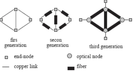
Figure 1: Three Generations of Networks1
In 1G, the whole network was electronic. Transmission medium was completely based on
copper cables (or radio waves), whereas the switching and routing was done through
electrical equipment. With the invention of optical fibers as means of transmission medium
for telecommunication signals, 2G networks exploited the high bandwidth and availability of
fiber in the access network, while the core (switching and routing) still remained in the
electrical domain. Although the huge bandwidth provided by optical fiber improved network
bandwidth to a large extent, it also invited the application developers to introduce new
features which were more bandwidth demanding. Soon the electronic core proved to be the
bottleneck of the networks and full capacity of fiber optics could not be exploited. This led to
1 Altan Kocygit, Demeter Gokisik, Semih Bilgen “All-Optical Networking”, Electrical and Electronics
the concept of third generation of networks called all-optical networks. In this network,
unlike its predecessors, the signal throughout end-to-end transmission remains optical. All
switching and routing is done completely by optical devices.
3.3 Conclusion
We discussed three generations of telecommunications networks. The first stage was based
only on copper, the second stage exists in today‟s telecom networks as „some fiber‟ and the
third generation future networks, when everything will be in the optical domain. We will
discuss the third generation of communication networks throughout this text.
4.
Optical Components Leading to AONs
4.1 Introduction
The devices that enabled the realization of all-optical networks in WDM environment are
discussed in this section. These devices are responsible for end-to-end transmission of optical
signals, ensuring the signal remains optical throughout.
4.2 Light Sources
The journey of an optical signal starts with the optical light source. It originates the light
signals tuned to a particular wavelength, and directs it on the fiber link at a particular angle.
A good light source in communications is referred to as the one that has a wide range of
price to make it more commercially feasible and attractive [8] [16]. Tuning time is a very
important factor of light sources. The source should be fast enough to avoid any bottlenecks.
Generally, for packet switching, a faster light source is required as compared to circuit
switching [8]. Various light sources are available, each with different characteristics and
technology. A choice of a particular light source depends on the application it will be used
for. Typically, tuning range (width of available wavelengths) and tuning time are the most
important parameters to consider.
4.3 Optical Fiber
Starting off with most important, and the base of, an optical network, an optical fiber is either
a glass or plastic hair-like fiber that is designed in such a way that enables it to carry light
waves along its length. The light waves form electromagnetic carrier waves that are
modulated to carry useful information. Use of fiber optics in communication technology has
enabled transmission over longer distances and at higher than normal rates.
There are three layers in a single strand of fiber, namely:
Core: is the innermost layer and is made up of Silica and a doping material. This is the layer that carries the light signal. A light wave once entering the fiber stays in the core
by the phenomenon, „total internal reflection,n‟ in which the light wave reflects back
Figure 2: Propagation of Light through an Optical Fiber.2
Cladding: is made up of pure silica and provides the high refractive index material that makes the light wave stay in the core.
Coating: is the external covering material that protects the glass inside. It is usually made of acrylate (plastic).
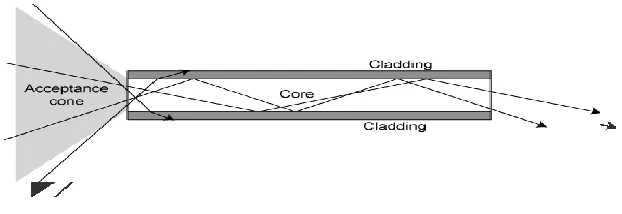
Transmission of optical signals through a fiber is accomplished by total internal reflection.
This phenomenon occurs when a light wave from rare medium (having low refractive index –
core) enters the denser medium (high refractive index – cladding), and it is deviated away
from normal (Figure 3). By increasing the incident angle, the corresponding refractive angle
also increases. The incident angle at which the corresponding refractive angle is 90° is called
„critical angle‟, any angle greater than critical angle will result in light reflecting back into the
rarer medium, thus resulting in total internal reflection.
Figure 3: Total Internal Reflection in Optical Fibers.3
The critical angle can be mathematically expressed as
Equation 1: Critical angle - Snell's Law. 4
Where,
is refractive index of cladding
is the refractive index of core
is the critical angle
Total internal reflection is achieved when
Equation 2: Condition for Total Internal Reflection5
3 M.S. Borella, J.P. Jue, D. Banerjee, B. Ramamurthy, B. Mukherjee, “Optical Components for WDM Lightwave Networks," Proceedings of the IEEE, vol. 85, no. 8, pp. 1274-1307, August 1997.
4 M.S. Borella, J.P. Jue, D. Banerjee, B. Ramamurthy, B. Mukherjee, “Optical Components for WDM Lightwave Networks," Proceedings of the IEEE, vol. 85, no. 8, pp. 1274-1307, August 1997.
Fiber optic cable is selected because of its vast advantages over other transmission media.
Because the transmission media is optic, therefore, more information can travel and that too,
with the speed of light plus optical pulses, are immune to electromagnetic interference (EMI)
and Radio Frequency Interference (RFI). It is not corroded by atmospheric conditions and
offers a very low BER (Bit Error Rate) of the order of 10-11. Fiber is flexible, and because it
is made with the cheapest resource on earth, i.e., sand, it is environmental friendly; unlike
copper it doesn‟t deplete natural resources. The only limiting factor for the bandwidth of an
optical fiber is dependent on the equipment that lights the fiber (e.g., laser).
4.3.1 Single-Mode Vs Multimode Fiber
There are multiple ways that an optical signal can travel through the fiber; each of these ways
corresponds to a particular mode. These modes are determined by the incident angle of the
optical beam. Ideally, total internal reflection can occur at any angle greater than the critical
angle, but light may not propagate through the fiber at all these angles. The reason is that,
some incident angles result in destructive interference, which doesn‟t allow light to
propagate. At other angles, it will cause constructive interference, which allows the light to
propagate.
All the angles that allow propagation of light through the fiber result in a specific mode. The
fiber that allows propagation of multiple modes of light is called a multimode fiber, and
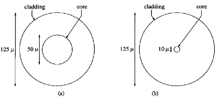
consequently the one that allows only one mode is single-mode fiber. Generally, fibers of
[image:38.595.117.471.152.318.2]thicker core are multimode.
Figure 4: (a) Multimode Fiber (b) Single Mode Fiber.6
One of the advantages of multimode fibers is that light could be injected easily on bigger core
and allow lesser coupling loss (the amount of power lost when the light is injected into the
core), for example, through an LED.
The following equation shows the number of modes, m in a multimode fiber:
Equation 3: Number of modes in a multimode fiber.7
where,
V is the normalized frequency which is given by:
6 M.S. Borella, J.P. Jue, D. Banerjee, B. Ramamurthy, B. Mukherjee, “Optical Components for WDM Lightwave Networks," Proceedings of the IEEE, vol. 85, no. 8, pp. 1274-1307, August 1997.
Equation 4: Normalized frequency.8
where,
,
a is the core radius,
is the wavelength of light in a vacuum.
The main drawback of multimode fiber is the introduction of intermodal dispersion. This
result is due to the difference in velocities of light for each incident angle; thus instead of a
sharp beam, multiple light rays are received at the far end, all separated in the time domain.
This effect increases with the distance between the two ends, thus offering a lower bit rate.
From Equation 3 and Equation 4, we see that the intermodal dispersion can be reduced by
decreasing the number of modes which can be reduced by decreasing the core radius,
reducing numerical aperture and/or increasing the wavelength of light.
With the invention of single mode fiber with a very small diameter of core [Figure 4(b)], the
problem of intermodal dispersion has been overcome. It allows only a single beam of light to
travel through, thus the signal can travel larger distances with limited signal loss. The
invention of single mode fibers is one breakthrough that paved the way towards all-optical
networks. The only problem with single mode fiber is difficulty in injection of light into a
very thin core. Thanks to the invention of lasers, this problem has been overcome to quite an
extent, further smoothing the way to all-optical networks.
4.4 All-Optical Wide-Band Amplifiers
Optical amplification is different from electro-optical amplification. Optical amplification is
considered 1R (regeneration), whereas electro-optical is 3R (regeneration, re-clocking,
reshaping). All optical amplification provides complete data transparency that is the desired
property for future‟s all-optical networks. 3R amplification tends to slow down the system‟s
overall performance due to lack of transparency, which makes it less practical for future
optical networks with higher bit rates.
In electro-optical WDM systems, each wavelength must be separated for amplification in
electrical domain and then recombined before further transmission. Electro-optical WDM
systems need multiplexers and de-multiplexers, whereas optical amplification can amplify the
entire WDM signal at once. Optical amplifiers use the concept of stimulated emission. Two
popular types of optical amplifiers are semi-conductor laser amplifier and rare-earth doped
fiber amplifiers.
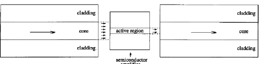
4.4.1 Semi-conductor Laser Amplifier
These types of optical amplifiers make use of an adapted semi-conductor laser (Figure 5).
Amplification is done by sending in a weak signal through the active region. Stimulated
Figure 5: A semiconductor optical amplifier.9
4.4.2 Doped Fiber Amplifier
These amplifiers exist within the lengths of fiber by adding an impurity (rare earth element)
which has a natural tendency of light amplification. Erbium is the most common rare earth
element used, which amplifies wavelengths of 1525 – 1560 nm. A strong signal is injected at
fiber end having lower wavelength (known as pump wavelength) which excites the rare earth
doping element. When data signal passes through these excited atoms, they stimulate them to
release photons which results in an amplified signal. This amplified signal is then normally
transmitted through the remainder of the fiber. These dopant elements are added throughout
the lengths of fibers at various intervals, thus providing optical amplifications as needed.
Figure 6: Erbium doped fiber amplifier.10
4.5 Optical Couplers
Optical couplers are the devices that split light out of the fiber or combine light into the fiber.
Splitters are the type of couplers that split the light out of the fiber into 2 or more fibers. The
reverse of a splitter is a combiner which combines light from 2 or more fibers into 1. Most
common types of splitters are 1 x 2 [Figure 7(a)], common combiners are the reverse of this,
i.e., 2 x 1 [Figure 7(b)]. A 2 x 2 coupler is simply a 2 x 1 combiner and then 1 x 2 splitter
[Figure 7(c)].
Figure 7: (a) Splitter, (b) combiner and (c) coupler.11
10 M.S. Borella, J.P. Jue, D. Banerjee, B. Ramamurthy, B. Mukherjee, “Optical Components for WDM Lightwave Networks," Proceedings of the IEEE, vol. 85, no. 8, pp. 1274-1307, August 1997.
4.6 Tunable lasers (transmitters)
These lasers are such that their wavelengths can be tuned as desired before transmitting.
Important factors to consider for tunable lasers are the tuning time (the time it takes to tune a
laser to the desired wavelength), tuning range (range of wavelengths) and whether the laser
can be tuned continuously within its range or whether only certain wavelengths can be
achieved discretely.
4.7 Tunable Filters (receivers)
Tunable optical receivers or filters are another category of devices that made WDM
all-optical networks a reality. Tunable all-optical filters are the ones that can pick a particular
frequency out of WDM signal. Tuning time and tuning range are important characteristics of
filters in WDM system. The range shows the number of possible channels that could be
filtered by the receiver. Tuning time and range become very important in scenarios like
WDM network when deployed with broadcast and select architecture.
4.8 Optical Switching
Current switching technique used in optical networks involves electro-optical conversions.
Whenever a signal through high-capacity fiber reaches a switch/router, before any processing
is done, the signal is converted back to its native state (electrical). Although electrical
switches are far more efficient, flexible and advanced and have high processing capabilities,
added electro-optical conversion each time the signal hits a switching device it results in
added delay and overhead to the whole system. This further limits the overall performance of
the system. Because of these reasons, an all- optical network concept has started to gain pace.
It has optical switching devices that are able to process and route data without having to do
any electro-optical conversions.
The control functions for switching in current optical-switching devices are still performed in
electronic domain but the data signals stay optical throughout. This means that the optical
signal is transparent to the switch and the switch is unaware of the signal format and its data
rate. Wavelength-dependant switches are also being developed for WDM networks.
All optical switches can be broadly classified into two main classes as discussed below.
4.8.1 Relational Switches
This class of switches institutes a relationship of the inputs with outputs. This relationship is
a control function of the switch and is not dependant on the actual input signal. The switch
performs the same control function or set of control functions irrespective of the input.
Directional couplers are one example of this class of switches. They perform either splitting
or combining irrespective of the data carried by the signal. Switches belonging to this class
can allow higher data rates as they cannot sense individual bits of the optic signal, instead as
a single continuous stream. This is called data transparency. Depending on the situation, this
flexibility since the individual portions of the signal cannot be sensed by the device and thus
cannot be switched.
Some of the commonly used relational switches are discussed below.
a. Optical Cross-connects
An optical cross-connect switches incident signals from input to the output. This switch is
considered to be wavelength independent because it cannot sense the wavelengths of incident
signal and cannot provide any de-multiplexing functionality. One of the very basic and
common optical cross connects is the 2 x 2 cross connect (Figure 8). It routes two input
signals to two output signals with 2 states; cross and bar. When the switch is in bar state, both
inputs follow the straight path to the output, i.e., input 1 to output 1 and input 2 to output 2
[Figure 8(a)]. When the state is cross, the two input signals are swapped at the output, i.e.,
input 1 becomes output 2 and input 2 becomes output 1 [Figure 8(b)].
[image:45.595.176.424.558.662.2]
Figure 8: 2 x 2 optical cross-connect (a) bar and (b) cross state.12
b.Non-reconfigurable wavelength routers
Wavelength routing is an important aspect of WDM networks. In a wavelength router a
mixture of wavelength received at one port is de-multiplexed into individual wavelengths.
This router can send each wavelength to designated port where different wavelengths
received can be recombined through a multiplexer into a WDM signal. The word
non-reconfigurable refers to the phenomenon that, when signal is split into its constituent
wavelengths, there are pre-defined fixed routes that a particular wavelength needs to follow.
There is no switching process during this stage. A non-reconfigurable wavelength router is
[image:46.595.170.429.407.631.2]shown in the figure below.
Figure 9: A 4 x 4 non-reconfigurable wavelength router.13
The decision of wavelengths forwarding to a particular port is pre-determined through a
matrix. This matrix is achieved through making permanent connections between
de-multiplexers and de-multiplexers.
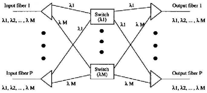
c. Reconfigurable wavelength router
This type of router offers greater flexibility in routing. In this scheme a WDM signal received
at a certain port is de-multiplexed into individual wavelengths. There is an array of switches
in column next to de-multiplexers as shown in the figure, each corresponding to a particular
wavelength. The switches can route a particular wavelength to a particular port. All
wavelengths received at a particular port are recombined into a WDM signal again. It is
interesting to note that each switch is a relational device, basically a 2x2 cross point element
receiving a fixed wavelength. This switch can be re-configured to a different wavelength
through tuning. Therefore, the overall routing is based upon the actual wavelength of the
Figure 10: A P x P reconfigurable routing switch with M wavelengths.14
4.8.2 Logic Switches
These are the switches that interpret the data stream incident on the input, then process
according to the information it carries and switch accordingly. The signal at the input controls
the state of the switch such that some Boolean functions are performed on it. Since the device
is interpreting the bits in the data and changing states accordingly, it should be fast enough to
pace itself with the input data rate (or faster). This causes a limit on the data rate of the
incident signal, although it does give the switch some additional flexibility.
Below we discuss some commonly used logic switches.
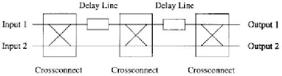
4.9 Photonic packet switches
The components discussed above are relational, i.e., they follow a pre-defined path for
forwarding the packets. Such components are suitable in circuit-switched networks. For
greater flexibility and scalable networks we need components in AONs that can perform
some logical decisions on packets. In these types of switches the forwarding is based on the
content of the packet instead of some pre-defined mechanism. Whenever there is any type of
logical decisions, the device switch becomes a constraint recourse. Many packets may arrive
before being able to be sent to the output port. This type of problem is easily solved in
electronic domain by introducing buffer in switches and routers. Saving electrical data for
some time is achieved through a series of flip-flops. But the problem of keeping data in
buffers when it is in optical domain is still somewhat challenging. There are some solutions
proposed for optical buffering, e.g., long rings of fibers may be introduced in the switching
devices to create an artificial delay. An example of optical packet switch is Content
Resolution by Delay lines (CORD) as shown in the figure below. By careful calculation of
[image:49.595.160.435.459.533.2]delays, the power and packet loses could be reduced to a minimum.
Figure 11: The CORD architecture.15
4.10 Wavelength conversion
In WDM networks each fiber carries a number of wavelengths. The devices‟ cross-connects
are responsible for transmitting the signal onwards either by routing the same wavelength to a
different port or by wavelength conversion. The optical switch treats each wavelength signal
individually. Wavelength selective cross-connect (WSXC) as shown in the figure 12(a) is
capable of sending a signal received on port and send it on to some other port.
Wavelength interchange cross-connect (WIXC) as shown in figure 12(b) is a device that
carries out the operation of wavelength conversion. It is with the help of this cross-connect
that the problem of „wavelength continuity constraint‟ – which means the light paths needed
to maintain the same wavelength all the way along the fiber, is resolved. It helps use network
resources more efficiently. WIXC is a complex device and offers greater flexibility to the
network model [33].
Figure 12: a) Wavelength selective cross-connect and) wavelength Interchanging cross connect16
4.11 Conclusion
In this chapter we discussed optical components that led to the concept of all-optical
networks. Most important network components like light source, wide band amplifiers,
optical switches and routers, tunable transmitters (lasers) and receivers are discussed. It is
16 Esa Hyyti¨a thesis “Dynamic Control of All-Optical WDM Networks” Supervisor: Professor Jorma Virtamo, HUT ,HELSINKI UNIVERSITY OF TECHNOLOGY Department of Electrical and Communication Engineering Networking Laboratory [online] available at
through the discovery of these optical components that all-optical networks could become a
reality.
5.
Multiplexing Techniques in AONs
5.1 Introduction
To fully utilize the vast bandwidth of optical fiber, concurrency can be initiated between
various users‟ transmission. This phenomenon is called multiplexing. In this section we
discuss various multiplexing techniques that are employed in all-optical networks.
5.2 OTDM – Optical Time Division Multiplexing
In this type of multiplexing, a single high-speed transmission channel on fiber contains
numerous ultra-short pulses that are time interleaved. These ultra-short pulses make up the
numerous low-speed user channels. By applying this multiplexing, a single fiber can be
exploited to transmit data between multiple users/nodes, thereby increasing the network
capacity by many folds. Since these short pulses are carrying all the information from one
end to another, both the transmitters and receivers should be perfectly synchronized to the
exact same channel (time slot) to make sure there is no interference.
5.3 CDM – Code Division Multiplexing
In this type of concurrent transmission technique, each channel is allocated a unique code.
unique codes. The range of codes is kept large to avoid a co-relationship between different
signals travelling over the same fiber. The overall network capacity with this approach is
huge allowing full utilization of fiber capacity. The restriction of synchronization at both
ends is crucial in CDM technology as well.
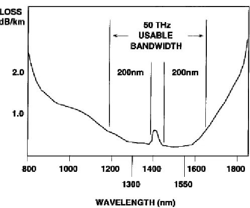
5.4 WDM – Wavelength Division Multiplexing
In WDM, the wavelength of the light waves is exploited to carry multiple data streams on a
single fiber. The existing spectrum of light (in its useable range 1300–1550 nm) is divided
into multiple channels, each supporting the data rate higher than the peak electronic data rate.
As a result the overall network capacity increases by the rate of each channel times the
number of channels. Since each sending and receiving end can send multiple channels,
multiple wavelengths are required. This is the reason tunable transmitters and receivers are
Figure 13: The low attenuation region of optical fiber.17
WDM is more popular than CDM or OTDM because of their complex requirements of
hardware and synchronization. Moreover, the hardware required for WDM is commercially
more available. The property of transparency of WDM also makes it a choice for present day
[image:53.595.173.422.76.283.2]AONs.
Figure 14: Block diagram of a WDM transmission system.18
Above figure (Figure 14) shows the block diagram of generic WDM network. A simple fiber
link can make up the network medium. The transmitter consists of either a laser or a
17 M.S. Borella, J.P. Jue, D. Banerjee, B. Ramamurthy, B. Mukherjee, “Optical Components for WDM Lightwave Networks," Proceedings of the IEEE, vol. 85, no. 8, pp. 1274-1307, August 1997
modulator. In case of multiple wavelengths, a coupler is required to unite the wavelengths to
be transmitted on a single optical fiber. Likewise, an optical de-multiplexer is required at the
receiver end to separate different wavelengths, which are then directed to a photodiode array.
Tunable laser can also be used to transmit a single wavelength and in this case, a tunable
filter is also required at the receiving end to filter the desired wavelength.
Figure 15: Transmitter and receiver structures.19
5.5 Conclusion
In this section we discussed three popular types of multiplexing that are used in all-optical
networks. The concepts of Optical time division multiplexing (TDM), Code division multiple
access (CDMA) and Wavelength division multiplexing (WDM) are discussed.
19 M.S. Borella, J.P. Jue, D. Banerjee, B. Ramamurthy, B. Mukherjee, “Optical Components for WDM Lightwave
6.
Architectural Forms of WDM Networks
6.1 Introduction
There are several architectural forms of WDM networks. Each has its own advantages and
disadvantages. In this section we will discuss some of the most common forms of WDM
networks. Basic architecture of each WDM network, its limitations in implementation and
advantages and disadvantages are discussed.
6.2 WDM Links
In second generation networks (2G - Figure 1), there are several parallel fibers introduced
between two end nodes; each fiber is designated for a single channel. The WDM link
network is practically an upgraded version of that. In this network, a single-fiber link replaces
all the parallel fibers. The different channels previously going on separate fibers are now
multiplexed on the single fiber using different wavelengths (Figure 16). All channels are now
amplified using a single-wide-band optical amplifier unlike 2G networks where each channel
required a separate amplifier. This increases overall system‟s cost efficiency and the existing
fibers are now being exploited proficiently.
WDM Link networks are popular because they are less costly and simpler to integrate with