FACULTY OF ELECTRICAL ENGINEERING
UNIVERSITI TEKNIKAL MALAYSIA MELAKA
THE INVESTIGATION OF THE POSITION CONTROL FINGER FOR REHABILITATION ROBOT USING 5DOF ROBOTIC ARM MANIPULATOR
MUHAMMAD REDZUAN BIN MARIKON
i
SUPERVISOR’S ENDORSEMENT
“I hereby declare that I have read through this report entitle “The investigation of the position control finger for rehabilitation robot using 5DOF robotic arm manipulator” and found that it has comply the partial fulfilment for awarding the degree of bachelor of Electrical Engineering (Mechatronics)”
Signature :………
Supervisor’s Name : PROFESSOR MADYA DR MUHAMMAD FAHMI BIN MISKON
ii
THE INVESTIGATION OF THE POSITION CONTROL FINGER FOR REHABILITATION ROBOT USING 5DOF ROBOTIC ARM MANIPULATOR
MUHAMMAD REDZUAN BIN MARIKON
A report submitted in partial fulfilment of the requirement for the degree of Mechatronics Engineering
Faculty of Electrical Engineering
UNIVERSITI TEKNIKAL MALAYSIA MELAKA
iii
STUDENT’S DECLARATION
I Declare that this report entitle “The investigation of the position control finger for rehabilitation robot using 5DOF robotic arm manipulator” is the result of my own research except as cited in the references. The report has not been accepted for any degree and is not concurrently submitted in candidature of any other degree.
Signature : ...
Name : MUHAMMAD REDZUAN BIN MARIKON
iv
v
ACKNOWLEDGEMENT
Firstly, special thanks to PROFESSOR MADYA DR MUHAMMAD FAHMI BIN MISKON as my supervisor for my final year project. He has guidance me throughout the period during doing my final year project. I am very appreciate all the advice from him in other to correct me and make me the best when conducting my final year project. He always motivate me to be more critical person and able to gain more knowledge about this final year project. He has teach and guidance me on how to prepared the good report and his willingness to teach me to create the good technical report. Moreover, he always share his experience about mechatronic engineering and industry culture that it is very good to implement in real world. Furthermore, I would like to thank my panels, ENG. MOHD BAZLI BIN BAHAR and CIK NUR ILYANA ANWAR APANDI for contribution from them to evaluate my final year project.
Secondly, I would like to thank to my family who giving full support and give good motivation throughout the whole research period for this final year project. They always encourage me to always be positive and be the best to complete my research and my study in this university.
vi
ABSTRACT
vii
ABSTRAK
viii
ix
TABLE OF CONTENT
CHAPTER TITLE PAGE
ACKNOWLEDGEMENT v
ABSTRACT vi
TABLE OF CONTENTS ix
LIST OF TABLE xii
LIST OF FIGURE xiii
1 INTRODUCTION 1
1.1 Motivation 1
1.2 Problem statement 2
1.3 Objective of the project 3
1.4 Project scope 3
2 LITERATURE REVIEW 5
2.1 Theoretical Background 5
2.1.1 Robotic Rehabilitation 5
2.1.2 Background of finger rehabilitation robot Model 6
2.2 Trajectory Generation 8
2.2.1 Joint-Space Scheme 9
2.2.2 Cartesian space scheme 10
x
2.3 The technique to generate the robot movement 12
2.3.1 The quarter circular motion equation for the robot 12
movement.
2.3.2 The parabolic circular motion equation for the robot 12
movement.
2.3.3 Comparison among Different Trajectory 13
Generation Method
3 METHADOLOGY 15
3.1 Theoretical description for proposed idea. 17
3.2 Flow chart for KUKA Youbot motion’s code. 19
3.3 KUKA Youbot workspace for finger rehabilitation 21
Simulation.
3.4 Consideration on the validity of the simulation. 22
3.5 Reliability of the data 23
3.6 Objective for simulation 24
3.7 Material and equipment 24
3.8 Setup experiment and simulation 25
3.9 Procedure of simulation 26
3.10 Accuracy analysis 27
4 RESULT AND DISCUSSION 28 4.1 Simulation for different length of patient’s finger. 29
4.2 Simulation to determine the smooth trajectory 30
for end effector of robot.
xi
4.3.1 The robot end effector position for different 32
length of patient’s finger.
4.3.2 The robot joint position during movement of 33
finger rehabilitation.
4.3.3 The robot joint velocity during movement of 34
finger rehabilitation.
4.3.4 The robot joint acceleration during movement 36
of finger rehabilitation.
4.3.5 The finger joint force and torque during 37
movement of finger rehabilitation.
5 CONCLUSION AND FUTURE WORK 39
5.1 Conclusion 39
5.2 Future work 40
REFERENCES 41
xii
LIST OF TABLES
TABLE TITLE PAGE
2.1.1 The comparison between two methods in trajectory generation. 13
3.2.1 The index finger force range limit 23
4.2.1 The variable data for the path point simulation 30
xiii
LIST OF FIGURE
FIGURE TITLE PAGE
2.1.2.1 Show the basic finger anatomy. 6 2.1.2.2 The finger trajectory movement. 7
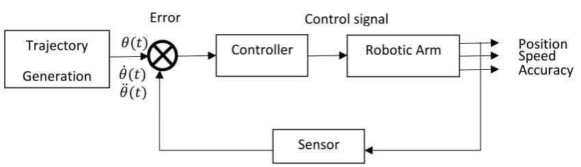
2.2.1 The Trajectory Generation Block Diagram. 8
2.3.1.1 Show the 4 different minimum rotation position to be choose. 11
3.1 The overall methodology process. 16
3.1.1 Scenario for Finger Rehabilitation robot work. 17
3.1.2 The trigonometry circle to find 𝜃. 19
3.2.1 flow chart for the algorithm of the finger rehabilitaion robot 20
3.3.1 the rotation limit and the length detail for the KUKA Youbot 21
3.3.2 The side view of workspace for the end effector during finger 21
rehabilitation simulation
3.3.3 The top view for the workspace of the robot during rehabilitation 21 simulation.
3.4.1 The index finger rotation limit 22
3.5.3 The V-REP simulation drawing setup to simulate the finger 25
Trajectory motion.
3.5.4 The experimental setup in V-rep. 26
4.1.1 The angular position of different length of finger. 29 4.2.1 The end effector trajectory with different no of path point. 30
xiv
LIST OF FIGURE
FIGURE TITLE PAGE
4.3.1 The different finger length position for the robot movement in 32
VREP.
4.3.2 The joints position for the robot movement in VREP. 34
4.3.3 The angular velocity of the robot in V-REP. 35
4.3.4.1 The angular acceleration of the robot in V-REP 36
4.3.5.1 The force for the joint at acceleration 37
1
CHAPTER 1
INTRODUCTION
1.1Motivation
Every year, 15 million people worldwide suffer a stroke. Of these, 5 million die and another five million are left permanently disabled [5]. Stroke in Malaysia is the third largest cause of death and estimated over 40,000 people are suffered in Malaysia. [6]. Loss ability by post stroke patient during movement their thumb and finger is critically issues observes by clinical and frequently reported by patient. The limited ability to activate the movement of finger and thumb extensor muscle is the main problem for the patient [1]. In order to increase the improvement finger and thumb movement, the targeted rehabilitation technique need to implement during rehabilitation session [2]. The targeted rehabilitation technique will make the recovery period faster.
2
Furthermore, using robot application in Malaysia will solve the problem for the rehabilitation instructor to monitor the patients frequently, it will give patient an advantaged to create the ability to do repetitive practice task during rehabilitation session in order to give repetitive practice for physical therapy to patient without the present of instructor [4]. In addition, motion of robot can be controllable and able to quantify the recovery progress performance make them suitable to calibrate the rehabilitation motion with the recovery progress [5]. Using this advantage, the rehabilitation session will goes smoothly with no human error by physiotherapists. Robot based rehabilitation will improve rehabilitation session more efficient because the no of finger rehabilitation robot can use more than three in a time. Make the more patient able to receive physical treatment in a period of treatment without need extra energy of physiotherapist. The robot will increase the effeteness of finger rehabilitation in future.
1.2Problem statement
The complex problem of control finger for rehabilitation is how to control the trajectory generation for initial angular position (𝑥𝑖), final angular position (𝑥𝑓), initial
angular velocity (𝑣𝑖), final angular velocity (𝑣𝑓), initial angular acceleration (𝑎𝑖), and final
angular acceleration (𝑎𝑓) for the 5 DOF robot to move during rehabilitation of index finger.
If the initial angular acceleration is increase, the jerk of the 5DOF robot will increase. Moreover, when the decreasing of the initial angular acceleration (𝑎𝑖), the jerk for robot will
decrease, but the time taken to complete one cycle of the robot finger movement will increase. Therefore, how to compare the acceleration and jerk based on the human joint finger force limit.
3
produce the movement from that equation so the movement of the finger will be the same as the movement of actual human finger motion.
The problem of control the accuracy of the robot is when the manipulator need to move the finger from initial position to the final position without produce much error and keep the finger joints will not getting hurt. The path description and generation for the trajectory of the robot need to synchronous with the of actual normal finger trajectory. This is because in motion of the patient finger during rehabilitation activity, the muscle need to generate like normal movement of the actual finger and the motion of path need to be specify during this investigation. The motion of path need to move the manipulator from the initial position to the final desired position.
1.3Objective of the project
The objective of this project are:
1. To investigate the finger control for rehabilitation using 5 DOF robotic arm.
2. To Design the Angular position (𝑥𝑖, 𝑥𝑓), angular velocity (𝑣𝑖, 𝑣𝑓) and angular
acceleration (𝑎𝑖, 𝑎𝑓) of the Finger rehabilitation robot using KUKA Youbot robot.
3. To evaluate the control of finger using 5 degree of freedom robot during the finger rehabilitation using V-REP software.
1.4Project scope
This project will investigate the how to control the finger motion by using the fundamental of the trajectory generation subject. The 5 DOF robot used in the simulation is only KUKA Youbot and not using other type of 5 DOF robotic arm.
4
investigation is able to control the finger motion during rehabilitation with the different size and length finger of the human. This investigation only focus trajectory of human index finger in the V-REP simulation software.
The boundary of research by using VREP simulation software is the gravitational force acting on the KUKA Youbot might be different compare to the actual KUKA Youbot in real world. The different value of gravitational force might affecting the velocity and acceleration in the VREP might be different compare to the actual KUKA Youbot. Therefore, in this investigation, the velocity and acceleration just focus for the VREP simulation software.
5
CHAPTER 2
LITERATURE REVIEW
2.1Theoretical Background
2.1.1 Robotic Rehabilitation
Nowadays, the development of robotic rehabilitation in other to help the patient in rehabilitation activity has increase in the biomedical engineering across the world. The robotic rehabilitation works in very complete task trajectory. This is because the robotic rehabilitation works in unpredictable environment and need to communicate with human ability to do some movement task in rehabilitation training. Robotic rehabilitation is more complex compare to industrial robotic manipulator.
In the biomedical engineering, there are many type of robot use in various task to rehab the patient like 3 DOF robotic arm use to move the movement of finger, the 7 DOF robot use for nursing robot [17] and pneumatic cylinder to generate the movement of finger. For those robotic manipulator, the trajectory movement is mostly generated by using trajectory planning. In the trajectory planning, there are two method basically used to generated the end effector trajectory. The method is joint space scheme and Cartesian space scheme.
6
and performance of the patient during rehabilitation training session. The visual based movement also make the robot able to learn the behaviour of the patient ability make the robot to decide either down scale or up scale the movement of the rehabilitation training.
2.1.2 Background of finger rehabilitation robot Model
[image:21.595.197.448.402.647.2]The anatomy of the human hand as shown in figure 2.1.1.1. The anatomy for human hand skeleton is consist of 27 bones. In this investigation, the focused is for index finger. For index finger, there have 3 joint and 4 bones for this finger skeleton. The joint consist of Distal Interphalangeal (DIP), proximal interphalangeal (PIP) and methacarpophalangeal (MCP) [14]. For the bones of index finger, there have distal phalanges, Middle phalanges, proximal phalanges and metacarpals. The related for this purposed into this investigation is, the MCP, DIP and PIP joint is need to consider on control of finger rehabilitation by using 5 DOF robotic arm.
Figure 2.1.2.1: show the basic finger anatomy.
7
hand wrist movement in other to improve the effectiveness for patient rehabilitation. The wrist movement is generated by using 2DOF robot [15].
[image:22.595.130.488.199.364.2]To generate the finger movement, the actual data from human finger movement is implement in this investigation. The actual finger movement from the research [16] is likely movement in parabolic circular shape perimeter. The figure is shown in figure 2.1.2.2 below.
Figure 2.1.2.2: The finger trajectory movement
Finger rehabilitation investigation need several method to gain analysis from the finger motion, to compare and analyse the result from this investigation. Form previous study, the method that apply in rehabilitation activity is vital in terms of accuracy of the position, acceleration, velocity, and angle of each finger joint. This is because every parameter need to synchronise with the normal finger motion of human.
The method use in [9] is the method to generate the finger motion using the combination multi ginger haptic interface robot controlled by surface electromyogram (EMG). The movement of the finger is generated by robot using exoskeleton actuator and the electrical activity of muscle respond is monitor and recorded trough the detection of EMG. This will able to monitor and control every muscle activity by controlling the movement of robot. The EMG is used to measure the bioelectrical signal come from the voluntary contraction of muscle. This signal will give lot of information about a person’s intent. It is useful method in other to find the actual normal finger motion in terms of contraction of muscle to be analysis and come out with the control system method [8].
Index Finger Movement of
8
During the rehabilitation for patients, the EMG system will estimate the joint angle of the patient finger. Joint angle is applicable to the robotic system. This is because to generate the finger motion, the angle for each joint in finger need to be estimated in actual position. The angle of joint will affect the muscle contraction. In addition, when the angle was determined, the calculation for different type of exercise can be calculate. This is helpful method in order to produce various exercise for the finger including flexion and extension. [9]. the finger motion for this system can be generated more than 3-directional motion
Furthermore, the hand rehabilitation support system based on self-motion control was developed [10]. The system was developed with the exoskeleton device that support using symmetric master-slave motion system that applicable for virtual reality environment. This is applicable for the patient that have one side hand or finger problem only. The motion is drive by healthy patient hand itself to control other hand that have problem to move.
The other application for robot rehabilitation for finger stroke is by using cable actuated rehabilitation system [11]. The system was developed to train each finger to move using cable loop linear displacement movement. The force from the movement will generated the movement of finger. This system have deferential sensing system and clutch system which allows every each finger movement independently using one actuator.
[image:23.595.103.528.512.634.2]2.2 Trajectory Generation
Figure 2.2.1: The Trajectory Generation Block Diagram.
Trajectory generation is the terms to describe the desired motion of a manipulator in multi-dimensional space. The terms trajectory is refer to the time, acceleration and velocity for every single degree of freedom for the manipulator. In investigation of control finger for
Trajectory Generation
Controller Robotic Arm
Sensor
Error Control signal
9
rehabilitation, we using the trajectory generation to specify the trajectory or path point in desired position to move the robot in the form of parabolic circular motion.
Using trajectory, the motion of every manipulator can easily generated through the specifying trajectory description for the desired motion. User can easily specify the desired goal position for the end effector to move the finger and let the system to determine the exact shape and path for the manipulator to move to the desired goal position. [11]. The movement for the finger rehabilitation robot depend on the initial position and final position that will define by the user. The trajectory motion for the parabolic motion of the robot will generated by the computer through the define point. Trajectory is computing on the digital computer. The trajectory point is computed at certain rate call path update rate. The rate is typically range between 60 and 2000Hz.
2.2.1 Joint-Space Scheme