• . . . . reverting again to the quotation from Matthew: "The Sage built his house and the winds and tides could not touch i t because it was bui 1 t on rock" (Book 6 - Verse 25), I was able to add: "But the Sage can build his hbuse too, on any ground 1if he calls in the services of an injector"'.
Dr Claude Caron (1982)
' ' -.. - ~ '. ~ ~
THE GROUTING OF LOW PERMEABILITY SOILS IN DAM FOUNDATIONS
by David M Brett B.E., M.I.E. (Aust)
A thesis submitted 1n fulfilment of the requirements of
the degree of Master of Engineering, at the University of
Tasmania, 1985.
:.:n
/ .. ; t(: ~!:;, 'v' U,P; I ~1 ,f;i, .. •.;:· .. Y( :: C 1 ' ,,j r - - ~ ... • .. 1•. , ...
This Thesis contains no material which has been accepted for the award of a degree or diploma in any University, and to the best of my knowledge and belief, contains no copy or paraphrase of material previously published or written by another person, except where due reference is made in the text .
.
.
. . .
...
.
. . .
.
.
.
.
"....
David M Brett
30
{tj?,
. . . . ...
Date
Installation of tubes a mane he t te f.or foundation a routing
at the Refinery Catchment Lale, Dam, Worsley Alumina
Refinery, 1981.
Preface
In 1979 the author was appointed by his employers,
Consulting Engineers, Gutteridge Haskins and Davey Pty Ltd as project engineer for the site investigation phas~ of a
feasibility study into the management of fresh water
resources and contaminated water at the proposed Wocsley
Alumina Refinery in the Darling Range of Western Australia.
He subsequently became project manager for the design
phase of the $40 million "Water Management System" for
which Gutteridge Haskins and Davey were responsible.
His total involvement with the project was completed when
he was seconded to the Project Managers Raymond Engineers,
Australia, Pty Ltd as an on-site technical consultant.
The Worsley
'large dams' , Large Dams
"Water Management System" comprised three
as defined by the International Committee on
(ICOLD) over twenty kilometres of diversion
channels, various hydraulic structures, lined·· . . water.
storage basins, tailings disposal
seepage collection systems.
areas and various
A particular feature of the project was a multi-backup·
environmental protection system to control water
contaminated by caustic soda and other chemicals •.rned on
the site.
The first level of protection invol~ed the constructidn of
a storage reservoir, called the Refinery Catchment Lake:,·
to the highest practical degree ~f water tightness.
Part of the design for this reservoir comprised tlle
'.: . . •.'.
Field testing conf ir-med that only low viscosity chemical
gr-out could effectively ceduce the already low
pecmeability of the foundation,
Chemical gr-outing of soils is a celatively cecent
engineecing development, and whilst a cectain amount of
expecience has been gained, pacticulacly over the past
twenty five yeacs, the pcoceduces to be used are far- fr-om
being pcecisely defined •
. Pr-actical field testing at the Refinery Catchment Lake Darn
Site indicated potential problems with some gr-outing
procedures used at other sites in the past. These
procedures related principally to the grout pressures and
injection volumes used with evidence that excessive
hydraulic fracturing of the low permeability soil was
counter productive to the overall aim of economically
reducing permeability.
The thesis describes the design of the Refinery Catchment
Lake Darn, reviews the history and theory of chemical
grouting and discusses some relevant case histories. It
then describes the development of a practical technique
used to inject cement/bentonite grout and a phenoplast
grout, Geo seal MQ4, into the dam foundations to achieve
the design requirements.
The thesis was prepared following
re~earch by the author to deepen his
general subject of chemical grouting.
post-construction
knowledge on the
Th~ thesis was written in the belief that the work carried
out at th~ Refinery Catchment Lake Dam was unique in terms
of the attempted reduction of already low permeability.
It is believed· that in documenting a major field operation
the thesis makes a positive contribution to the increase
in knowledge of low perrneabili ty soil grouting techniques
and points to areas where additional academic research is
required.
ACKNOWLEDGMENTS:
Many people have helped
this thesis, firstly in
project work and secondly
presented here.
and influenced my work
association with the
in the preparation of
towards original
the text
Special acknowledgment is due to: my employers Gutteridge
Haskins an.d Davey Pty Ltd, particularly Mr John Phillips, Director, for this faith in my ability, often far beyond
my own; my associates, Dr Glen Truscott for his calm logic
and, David Coheny for his invaluable preliminary
research;
particularly
Project Managers,
Kas. Sobejco whose
Raymond
support of
Engineers,
technical
requirements over contractural expediency was probably the
major influence on the technical success of the project;
the Contractor, GFWA Pty Ltd, particularly Trevor
Osbourne, for his practical advice; Worsley Alumina Pty
Ltd, particularly the project liaison officer, Jim Irish
for his interest in the project and his personal
encouragement towards the preparation of this thesis,
Staff of the University of Tasmania, particularly Dr Greg
Walker for his early advice; my supervisors Brian
Cousins, Bruce Cole and Mike Fi tzpa trick for their
constructive criticism and guidance; Lynne and Shelley
for their translation of my manuscript and their wonderful
typing, and lastly my wife, Margaret and my family who
h h. 1 i kh k V L L, 1 N n P' 0 p Po Q q R
RP
r = ==
==
=
==
=
=
=
=
=
=
=
=
=
=
=
=
=
=
=
=
=
=
=
=
=
=
=
=
=
=
=
=
2area (m )
NOTATION
Skemptons pore pressure, parameter
effective spherical radius of a grout source
(m)
distance of grout front from source
width of dam base
a shape constant
depth of overburden (m)
depth of grout curtain (m)
effective diameter of a soil particle (m)
Youngs modulus of elasticity
efficiency of a grout curtain
void ratio of soil
applied hydraulic head (m of water gauge) grout injection head (m of water gauge)
hydraulic gradient
co-efficient of horizontal earth pressure
Darcy's co-efficient of permeability (m/sec)
Cozeny-Carman factor
apparent permeability of
(m/sec)
soil to grout
horizontal permeability (m/sec)
vertical permeability (m/sec)
length ( m)
length of injection hole (m)
borehole expansion pressure ratio
porosity of soil
effective overburden pressure (Pa}
grout pressure (Pa)
internal pressure in grout hole (Pa)
flow rate (m3/sec}
grout flow rate (m3/sec)
radius of grout front at time t. (m)
effective soil pore radius (m}
radial distance from grout hole centre (m)
radius of grout hole (m}
radius of plastic zone (m}
specific particle surface area 'cm 2 }
St = t =
V
=,
w
=
€ s
V
=
=
==
=
=
==
=
=
*
Note:soil tensile strength (Pa) time (secs)
velocity of flow (m/sec)
width of a flaw in a grout curtain
number of flaws in a grout curtain
bulk density (N/m3)
density of grout (N/m3)
density of water (N/m3)
dynamic viscosity (Pa.s
=
103cP)*
viscosity of grout (Pa.s)
plastic viscosity (Pa.s)
Viscosity of water (Pa.s)
shear strain (m)
Poissons ratio
radial stress from soil forces (Pa)
tangential stress from soil forces (Pa)
vertical stress from soil forces (Pa)
radial stress from seepage forces (Pa) tangential stress from seepage forces (Pa)
vertical stress from seepage forces (Pa)
shear strength (Pa)
undrained shear strength (Pa)
The correct unit for viscosity in the SI system is Pa.s.
The unit centipoise (cP) equal to l0-3Pa.s is used in
THE GROUTING OF LOW PERMEABILITY SOILS IN DAM FOUNDATIONS
Table of Contents
Section
Preface
Acknowledgments
Notation
Chapter 1 - Introduction
Chapter 2 - The Worsley "Water Management
System"
2.1 Introduction
2.2 The Water Management System
2.3 Site Geology and Soil Characteristics
2.4 The Refinery Catchment Lake Dam
- Description and Geology
2.5 The Refinery Catchment Lake Dam
- Seepage Analysis
2.6 Decision to Grout
Chapter 3 - Grouting General
3.1 Early History
3.2 The Tube a Manchette
3.3 Types of Grout
Chapter
4.1
4.2
4.3
4.4
4.5
4 - Groutability of Soils
Introduction
Permeability
Rheology
Penetration of Grouts
drout Penetration by Soil Fracturing
Chapter 5 - Hydraulic Fracture
5.1 Introduction
5.2 Observed Nature of Fractures
5.3 Mathematical Models
Page No.
V
vii
viii
TABLE OF CONTENTS (contd)
Chapter 6 Grouting of Soil Foundations
Construction
6.1 Discussion
6.2 Examples of Grouting of Soil
Foundations in Dam Construction
in Dam
Chapter 7 - Grouting of the Refinery Catchment Lake Dam
7.1 Design Phase Grouting Trials
7.2 Design Development
7.3 Contractor Selection
7.4 Development of Grouting Techniques
7.5 Construction Phase
7.6 Results
7.7 Post Grouting Performance
Chapter 8 - Summary and Conclusions
8.1 Summary
8.2 Conclusions
8.3 Further work
References
Appendices
A Submission for 1983 I.E. (Aust) Engineering
B
C
D
Excellence Award
Brett D. M., and Osbourne T. R., Chemical Grouting of Dam Foundations in Residual Later i te Soils of
the Darling Range, Western Australia, 4th ANZ
Conference on Geomechanics, Perth, 1984.
Brett D. M., Grouting of Low Permeability Soils
using Tube a Manchette Techniques, Proceedings,
Conference of the National Waterwall and Drilling
Association, Bunbury., Western Australia, 1982
Brett D.M., Chemical Grouting for Dams, presented
CHAPTER 1
INTRODUCTION
This thesis deals with the engineering practice of
grouting, defined by Bowen (1981) as " the injection of
appropriate materials under pressure into certain parts of the earths crust through specially constructed holes, in
order to fill, and therefore seal, voids, cracks, seams,
fissures, or other cavities in soils and rock strata".
The grouting of rock strata using cement slurry is a well
known technology with a documented history of almost two
centuries.
In his keynote address to the Conference on Grouting in
Geotechnical Engineering, held in New Orleans, February
1982, Adam Clive Houlsby went so far as to suggest that
experienced personnel "can nowadays carry out cement
grouting as an engineered process in order to achieve
specified standards of workmanship".
Unfortunately the same cannot yet be said of the chemical
grouting of soil foundations.
The first documented case of successful grouting of soils
by chemicals was by Joosten in 1925. Since th~n,
particularly in the past twenty five years, the technology
of chemical grouting has made dramatic advances. The
range of chemicals available and the infinite variability
of natural soils, however, makes the subject of soil
grouting extremely complex.
The documentation of completed projects is not extensive
This thesis reviews the history, theory and practice of chemical grouting of soils, particularly as related to the construction of grout curtains in dam foundations.
CHAPTER 2
THE WORSLEY "WATER MANAGEMENT SYSTEM"
2.1 INTRODUCTION
The Worsley Alumina Refinery is located on the headwaters of the Augustus River, about 200km south of Perth in the
Darling Range of Western Australia. The area is indicated
in Figure 2 .1.
Detailed engineering investigations and design for the
work commenced in 1979 with construction being completed
over the period 1981 to 1984.
The refinery processes bauxite by the Bayer process. This
process involves the extraction of alumina from the ore
using a hot, concentrated caustic soda solution.
Approximately three tonnes of ore are processed to produce
one tonne of alumina. The remaining 'bauxite residue' is
filtered, to remove the majority of the caustic liquid,
and is disposed of on site by a dry stacking technique.
Stormwater run off from the site and leachate from the
bauxite residue stacks is expected to contain a proportion
of residual caustic soda and other chemicals which would
lead to an increase in pH and salinity in the receiving
waters if not' controlled. As the Augustus River is
claimed to be a particularly low salinity water source and
one of the few remaining developable water resources in
the south west of Western Australia, the environmental
protection of the river was a major factor in the State
Government's approval of the scheme. The developers were
legally committed to fully utilise the extent of modern
engineering technology to achieve complete control. The
resulting "Water Management System" comprised a system of
dams, channels and groundwater bores designed to collect
and contain any contaminated water whilst bypassing the
W[IT[RN AUITR AL IA
PERTH
.
~---)
~·
Wellil>Q!OO . ~ \...
Dam q/ l
Q~
Figure 2.1. Worsley Alumina Refinery - Location
·-Fresh water diversion channels
Fresh water lake
Refinery site
from r:iine
Bauxite residue
1 disposal area
\ Solar evaporation
ponds
\
catchment
j
. .
. - Fresl" wat.er d1vc:.-s1on
/ channel
--
--
The author was associated with the investigations, design
and construction phases of the water management system through his employment with the consulting engineers, GHD
Dwyer Pty Ltd, a subsidiary of Gutteridge Haskins and
Davey Pty Ltd.
This company was responsible initially for feasibility
studies for the major shareholders in the venture,
Reynolds Australia, Alumina Pty Ltd and later for design,
as consultants to the Project Construction Managers,
Raymond Engineers, Australia Pty Ltd.
2.2 THE WATER MANAGEMENT SYSTEM
A plan of the refinery site indicating the essential
features of the water management system is shown in Figure
2.2
The site is located in one of the highest rainfall areas in Western Australia, with the average annual rainfall.· of
1350mm being only slightly lower than the annual
evaporation of 1490mm (Gutteridge Haskins and Davey, 1980).
TABLE 2.1 shows the monthly rainfall and evaporation
figures.
Table 2.1
Monthly rainfall/evaporation
-Worsley Refinery
Month Average Rainfall (mm) Average Evaporation (mm)
January 14 220
February 16 200
March 30 160
April 58 85
May 187 60
June 278 55
July 268 65
August 205 70
September 139 75
October 98 110
November 40 160
The separation and disposal of uncontaminated surface run
off water is critical to the success of any control system
for contaminated water.
The major sources of contamination are run off from the
and seepage from the
refinery site itself and run off bauxite residue disposal stacks.
collected and discharged directly
Contaminated water is
by gravity or indirectly
by pumping, via the Pipehead Dam, to the Refinery
Catchment Lake.
This lake, which is situated beside the refinery process
area serves as both a
as a cooling pond for
station. The use as
storage for contaminated water and
the refinery's coal burning power
a , cooling pond results in a
significant increase in evaporation, enabling, with
maximum diversion of fresh water, operation of the lake at
a stable water level. The lake has been siz~d with
sufficient freeboard such that even the most severe
conceivable combination of rainfall/evaporation events
would not lead to any spillage.
During drought periods top up of the Refinery Catchment
Lake can be effected by pumping from the Fresh Water Lake,
a 6000 Ml storage located downstream.
Prevention of contamination of surface water or
groundwater is ensured in the system design by:
a) Maintenance of pre-construction groundwater flow lines
towards to Refinery Catchment Lake.
b) Minimisation of seepage from the Refinery Ca.tchmen t
c) Collection of Disposal Areas
seepage from
by a patented
the Bauxite Residue
draihage system which
separates and controls groundwater and leachates.
d) Maintenance of a water table "sump" at the Pipehead
Dam as a 'secondary' collection system for any seepage
bypassing primary controls.
e) Location of a fresh water supply downstream of
critical areas which indirectly ensures the refinery's
owners interest in proper management of the system.
f) Regular monitoring of surface water and groundwater
status at dozens of measurement points and boreholes
around the site.
The sys tern is described fully in GHD Dwyer' s successful
submission to the Ins ti tu tion of Engineers, Australia, WA
Division for their Engineering Excellence Award of 1983,
attached as Appendix A.
The project was also successful
WA Chapter of the Association
in its submission to the
of Consulting Engineers,
Australia, for their 1984 Excellence Award.
The dams and structures have been described by Truscott
and Brett (1983).
This thesis deals in detail with Item (b), the minimising
2.3 SITE GEOLOGY AND SOIL CHARACTERISTICS
The site geology and soil conditions have been described
by Gutteridge Haskins and Davey (1980), Gordon (1984) and
Gordon and Smith (1984).
The rock types found in the Dar 1 ing Range are granites,
quar tzi tes and gneisses, of ten with instrusions of
dolerite dykes and quartz seams. Much of the rock has
been subject to intense shearing and is deeply weathered
due to the combined effects of high rainfall, high
evaporation,
vegetation.
high
Depths
water tables
to bedrock in
been recorded at over forty metres.
and the extent of
the Worsley area have
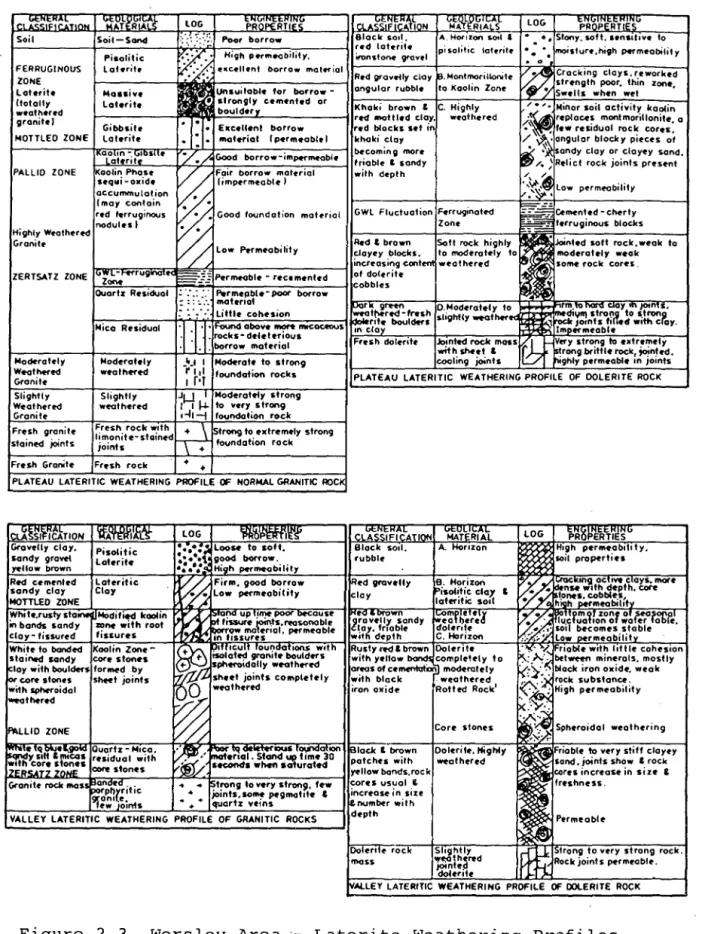
The soil profile conforms generally to the classical
laterite model with ferruginous, mottled, pallid and
zersatz ('rotten rock'), zones described by Gordon.
Two distinct sub groups of weathering profile are reported
by Gordon, being the 'plateau' profile (developed with
relatively low water table) and the 'valley' profile
( developed with relatively high water table) • Figure 2. 3
shows the various profiles derived by Gordon with notes on the characteristic properties of the different soils.
Gordon and Smith (1984) summarised the various engineering
properties of the most significant soil type, the pallid
zone.
The results were obtained from numerous laboratory and
insi tu tests related to dam site investigations and the
refinery piocess plant site investigations.·
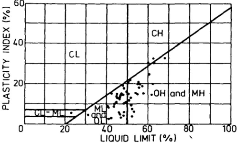
Atterberg limits indicated predominantly ML and MH
r-i:rRt1~~-.'"Cl:~~t:XJ:-:-r~LO:G:-:r-~~tp~NROG!Rrl~tR~TT~/1;m:-i~~-,r.~--cA~~t'Fl'l~,~.rmr..'\~\,n-,N--,-c,;~A~,rntR~lrrA~LS:r--,-7l~O~G,---ttP~RR~i·11~~~~ttr.T'R'm~~~u---, Moderately Weathered Granite Slightly Weathered Granite
Fresh granite stained joints Fresh Granite
::·:_:_:/:~ Poor borrow Black sod. A.Horizon s.o,I & • •. Stony,soft, 1•ns1t1v• to
Z
• Hu;h.
Pttffle,ob1hty,. .
r•d loterit• H"Onsto~ 9"0vel pisolitic lotuite- • • •• moistur1,h19h s>«meabtlity •0
•• (·. ·,(,.- e•c•llent borrow mate-rial '.,<'::; Rtd grav•Hy clay 8.Montmorillonit• / ~ c racking cays, reworked · I
t---i,lmltd!,(,!--..,-.---i
angular rubble to Kaolin Zone • strength poor. thin zone,Unsuitable for borrow - Y Swells when wet
strongly cemented or
1---l'"lli'"• .,,...:b.:o.:u.:..ld:::.e:.;r...,·y'---~ Khaki brown ,. red mottled clay. & C. Highly w,athered ;' ~"~"'• Minor soil activity kaoCin replace~ montmorillonite, a E•cellent borrow red blocks set in • 'l few res,dual rock cores, moterial ( permeablt I khaki clay "'. ~\' angular blocky pieces of
· • / • /,. Good borrow-impe,rnwoble becoming more ,a( ,:~ sandy cloy or clayey sand.
/ ·/· friable & 5andy ~/.~Relict rock joints pre-sent
V /
F~ir borrow mat,rial with depth / /v.~
(impermeable I~:~..J.
Low permeability•
. : • : Good foundation mat.-r,al GWL Fluctuation Ftrruginote-d
~~
C.f'mented-ch•rty Zone ~ ferruginous blocksV ./
Red & brown Solt rock highly~
Ill • Jointed soft rock, weak toV //
low Ptrmeabilily clayey .blocks, to moderately to ,l moderately weak/ / 1ncreas1ng contffl w•othered ~· some rock cores.
l"G11it:=F<muglnafi<~~~~==:;:;:-:-;:===;:-:;-1 of dolerite ~ ,
i-::.::::.~---,--~::::=:-~ .... ·.:w=-1-Pt-rmea __ b_l_e_-_re_c_•_m_e_n_te_d_~ cobbles : ·: .: :: Pwrmepble-poor borrow
_ .. _.. moter1al , ... ,"nc ~ n
1 - - - + s · ,...·..._· ..,·~l~i_tt_l_e_c_o_h_e_s1_·o_n_-_ _ _ . ; : : ~ r ~ l ~ ~ Mica Residual
·J :
'J:
=-~'::~:;:smtcoceous ~:ec~~Ydolerite:1 . l . borrow mater.al
O.Moderately to .... .,. rm.to·-~ aay "'Jatn,s, · t dtYfft strong to strong shghtly wea her"' ~ .. , rock J0tnls filled with cray.
~ ~ Impermeable
.lotnled rocl< mass {. ,-Very strong to utremely wrth sheet & J,,'-~ strong brittle rock, ;.,;nted. coaling joints U highly permeable 1n joints Moderately
wtalhered
-~-' I Moderate to strong r 11 I foundation rocks
, r•T PLATEAU LATERITIC WEATHERING PROFILE OF DOLERITE ROCK Slightly
weathered
Jl-,1 I Moderately strong I I µ. to Yflry strong 1-ll - j foundation rock Fresh_ rock -:1th ~ Strong to extremely strong hmon1te-sta1ned f d f r k
joints + oun a ion oc
Fr.,sh rock + +
PLATEAU LATERITIC WEATHERING PROFILE OF NORMAL GRANITIC ROC~
Wh1 le.rusty sta in bands sandy clay- fissured White to bonded
stained sandy core stones lay with boulders forfflf!d by
c:ore
stones sheet joints wi1h spheroidalthered
Core stones
Oolerite, H;ghty weathered
increase in size
enumber with ~V_A_l_L_E_Y~L-A_T_E_RI_T_IC~w-E·A-T_H_E_R_I_N_G~P-RO_F_I_L.E_O_F~G_R_A_N_IT_I_C~R-O_C_K_S~--t depth
Figure 2.3. Worsley Area
Oolert fl rock Slightly
mass
mt~~red
dolerite
Laterite Weathering Profiles
~
0 X w
60
0 1.0
z
>- I-u
i= 20
V) <t _J a.. 0 CL
I.I - JYIL
.
/. /
20
/
CH
/
/
~ /
V.·
~·
..
/
.
.
..
'
.
.OH and MHI:'~
'.
,.
-;_.,.
..
.
1.0 6J tlJ 1( 0
LIQUID LIMIT(%) '
PLASTICITY CHART- GRANITIC CLAYS
&
SILTS
60 ~ 0 X w 01.0 z >- I-u
.:: 20
V) <t ....J a.. 0 CL ,, LL -ML /
Ml i / '
20
V
CH
·:,;
/
.
I /
~ ••••~
..
.
.
..
,,
. .
/
/
.
OH and MHl~
..
•1.0 60 80 100
LIQUID LIMIT (%)
PLASTICITY CHART- OOLERITIC CLAYS
&
SILTS
Figure 2.4. Worsley Area Soils
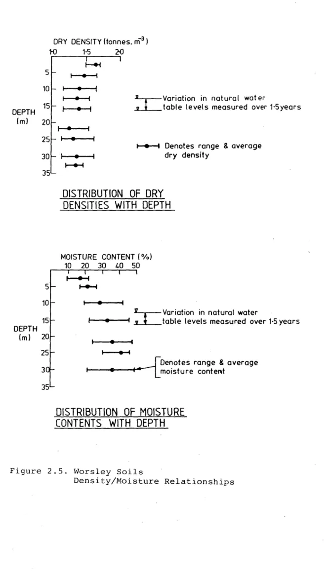
The extreme variability of the laterite soil types is indicated by the variation of dry density between 1.05 and
1. 76 tonnes per cubic metres, and moisture content, from
10% to 60%. A trend for decreasing dry density with depth
was noted. These results are presented in Figure 2.5.
Peak shear stresses measured by Camkometer ranged between
214 and 806 kPa with an average of 429 kPa. The
Camkometer, described by Wroth and Hughes {1973), is a
highly sensitive instrument developed at Cambridge
University for measuring lateral stresses, undrained
stress-strain properties and drained peak
of clay. The instrument consists of a
shear stresses hollow cylinder
which can drill itself into the ground,_,with a minimum of
disturbance. The unit used is operated by the University
of Western Australia.
strength with depth
Gordon as related to
A general trend of decreasing shear
was noted. This was explained by
the reduction in the proportion of
cementitious sesquioxides which give laterite soils their
characteristic quasi-overconsolidated parameters.
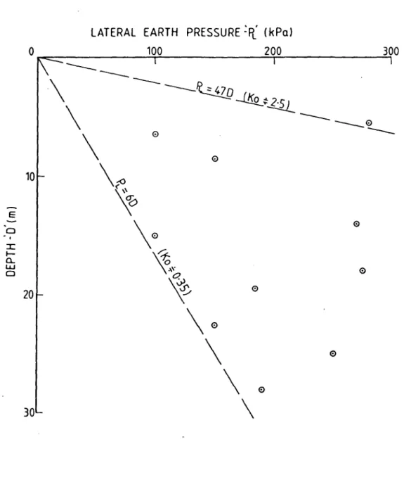
Lateral earth pressures measured with the Camkometer are plotted in Figure 2.6.
There is no apparent correlation between lateral earth
pressures and overburden pressure
approximately 0.35 to 2.5.
with K varying
0 from
Parameters measured in over 30 oedometer tests included
calculation of overconsolidation ratios from 1.2 to 4.0
with an average of 2.7.and standard deviation of 0.6.
The modul~s of elasticity {E) was calculated at from 7 to
42 MPa with an average of 26. Poisson's ratio ( v) was
DEPTH
(ml
DEPTH
ORY DENSITY (tonnes. m-3 l
rO 1·5 2-0
5
10
15
20 I 25
30
35
I
1---+i • I
•
•
I•
I•
I•
I•
r-+-4
~Variation in natural water
..L...1__ table levels measured over 1·5years
...-1 Denotes range & average dry density
DISTRIBUTION OF DRY
DENSITIES WITH DEPTH
MOISTURE CONTENT ( %l
10 20 30 1.0 50
~
5 ...
15
~ Variation in natural water
- - - • - - • .i..l_table levels measured over 1·5 years
(ml 20
•
25
3
35
I e I
. __f
Denotes range & average~
L
moisture contentDISTRIBUTION OF MOISTURE
CONTENTS WITH DEPTH
Figure 2.5. Worsley Soils
-
E0 I I
t-a.. w 0
LATERAL EARTH PRESSURE
~fl
(kPa)0 100 200 300
----\
--
---~
-1.!SQ_:
2il_
\
--
--0
---\
00
10
\<°
~
°2>
\0
01,~
~
20 ~ 0
\0
\
0
\
030
\
Figure 2.6. Lateral Earth Pressures vs Depth (from camkorneter testing)
0
i
!
ij
I
I!
I
I·
2.4 THE REFINERY CATCHMENT LAKE DAM - DESCRIPTION AND
GEOLOGY
The dam comprises an earthfill embankment approximately
600 metres long with a maximum crest level approximately 25 metres above natural creek level.
The embankment cross section as shown in Fig. 2.8 is
characterised by an upstream inclined core. Outer earth
shells both up and downstream are armoured by rockfill to prevent erosion.
A key trench under the core penetrates the surf ace soils
to a depth of up to 4 metres.
Internal drainage is provided by an inclined chimney
drain, a downstream sand/gravel blanket drain and relief
wells.
As described earlier, the water stored in the lake will
eventually become caustic and highly saline. The dam
design includes no spillway or scour pipe since the
evaporation, enhanced by the cooling pond effect, is
sufficient to match inflow into the lake.
- - - - ---
-Site investigations included bulldozer and excavator
trenching together with diamond drill holes, friction cone
probe holes and geophysical investigations. A number of
falling head permeability tests were carried out as were
several lateral earth pressure tests with a borehole_
pressuremeter. A cross section across the valley on the
dam axis indicating geological features and test results - - i
I
is shown in Figure 2.7.
- - - I
- -- - - -- --·~-- -
----The geology of the site was found to be typical of the
CiOl.flfT( OTd
A""'IQ&,STltr•(Tl:I"
""
.
JOO 11
346!
~SI.Jlf.l"(1'tll
,. ••• s ...
t · • • ...
c.-1, ...
Pll[SSuJl(l"Otl P\•U
-' t · t l ,..
c •• , ...
.B.t.LI....L _ll.U.L.Q_
50
100
150
100
150 i-:·:
GQJ...a!J~i;,T(
277';-l1'1
IX(A/A!Olf
"
.
"llfS~ll:[r-fTfA
Pl.•19 ....
t•OlJl'Pa
[•ltl'\Pol
wU#[l'"fT(II 0'7 ....
U51'1Pi JS "Pa
·-·
. ' ' ' l., ]fltl(SSUll(Olfltll (•411".PliA[OCLJ.1'0 Sll,J'I'
l"..0 IVII
IIIA11Al (w•lt'•PQ
11 .. -0
43·30 45·0
50-0
NOTE:
INCLINEO BOUNOARIES SEMEN THE MATERIALS
FOR RClQ e ONWARDS tOCATE THE RANGE CF POSSIBLE Bot.MlARY LOCAT~S. NOT THAT THE
STRATA ARE JN(LINEO.
I
I /
I I
____-1
I
~
.YiEfil.!.I..0 5 1: 200
~
t I
1-500
Figure 2.7.(a)
RCL Dam Site Geology
Longitudinal Section
Left Abutment
I)
l<'m
, / / , , / 150 200 PflUUlltl"lfTtlt Pl•lt,.,.. f•OJl'I,._ ,
..
,.,.,. CUT/
..
" r,i"':,"imi. ~ii,"l;;;~ii,i,T:~=====;!:!::;:::;;~~ H Bt .. , ...
•• \l""'
"
"
1S O ,. °'
"
,,, "
..
200 A.,
.. u
,.,,.,
'"
~i
·---"°-~ . ..!Qf_g: EMBAN~M[NT Rl 286 000 I
/~'=·~'="'t~·~·~"~s·~···~'~'·~·~I-"'"~··~•_.,;~
J 0• WN ltiJSTJ Al 1t1Trt Oil
150 t'.1
..
..
20 0
=-=·
..
•HIT( WY Q.Af(l" SAIO
Tltl.UIU tSCI
t•nr '"'""'°-•
r •10tfl'o """"'"'°~
..
25 0 2:,2I
~
o-0 RL mac
Slfol\
so
cr,,10
PD•TS
10-0 I
... :11·
200 1
---:--o
-:::.~,~
,.
,.
, - - - .,,.,f! ~•C·1•,.,!J -·-··• I
_
_j
"'""\
•, . , " " ' •11 I
1111>"\
.,.,a.10-1.,,,
~,i.\ .,.10.10·7.,,, I
LEGEND
II::'(' TYP( 8CJIICA1n"
ltOCl SIJQfA(f IOT70!'1 Cf 0(.-ATION
SHl.U la.II
Ql.llffl SIA"IS
OOl.fll1Tt Glt..,.!T(
C(l'll:Nf[O UT[IIIT( \llGN"TlY Wf:dH(ll(O rrQO{hf(lT •'U.htl:11(0
(Of'lfl'Lft{lT W{.l1H(ll[O GU\11[ 200 250
; l
I
150,., ... s
I ,,.,,. '°·• .,,
I 11 °11, 10~•11
20-SO
IIOCll.h(Ol,ltlT[R{O
!GRANOOrORIHJ
G,11Ao'(l5
GR•V(U.1" (LU CUY(Y GUVllS
\ILT•C.AAWU f'lll1Vll~S
SlllS·LO"lf P,aSTICITT
C:1111 LC!SS
Figure
500 \ '·. 51 so
/
/
/
~
______ , ____ s ___ ,,.
2.7.(b)
RCL Dam Site Geology
Longitudinal Section
PO(l{('I PCll'CfltOl'lf:T[I: l>(lOalfGS 1100•""'1
Permeability testing indicated that the foundation soils
were reasonably tight with
indicating permeabilities less
the
than
majority of tests
-6
10 metres/second.
However, several tests indicated moderate permeability,
around 10-4 metres/second, associated with sandier
materials particularly around the bedrock/soil interface
(zersatz or quartz/mica residual). This zone was exposed
in various areas adjacent to the dam site where bed rock
was close to the surface and was noted to be water
leaking. The permeability relationships of the soil
profile suggested by Gordon (1984) were not convincingly
demonstrated; however, within the limitations of the
investigations, there was evidence that more permeable
bands could exist through the foundations.
2.5 THE REFINERY CATCHMENT LAKE DAM - SEEPAGE ANALYSIS
To assess the effects of seepage through and under the dam
a detailed two dimensioned seepage analysis was carried
out using a finite element computer programme, RESEP,
developed at Sydney University. The programme was
expanded to enable a mesh of 622 nodes. This was
necessary to enable the study of combined seepage through
both the foundation and the embankment.
For the purpose of seepage analysis, features of the
foundation were modelled as:
1. Impervious rock at average 20 metres.
2. Cut-off trench to 3 metres intercepting surface
permeable features.
3. Optional one metre thick sand layers at depths of 9
metres and at 19m (above rock level).
4. Optional ~ingle row (3m wide) or double row (Sm wide)
These features are shown in Figure 2.8.
The cross section adopted for analysis corresponded to the cross section of the dam at maximum height and the inferred foundation conditions at the same location. These foundation conditions were considered to be the worst likely conditions that could be encountered along the entire dam length. For these reasons, i t was necessary to model one critical' section only.
As the hydraulic head would be lower for sections further up the abutments, seepage per unit wall length will decrease at these sections. It was conservatively estimated that total seepage quantities would be equivalent to 350 metres width of the adopted profile.
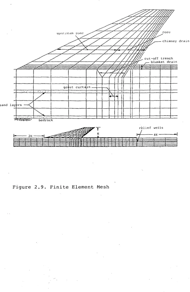
Features included in the mesh used were as shown in Figure 2.9.
1. Provision for upstream shell).
two upstream zones ( ie, core and
2. An inclined chimney drain of variable width downstream of the core. The chimney drain can be up to 3m and
three elements wide.
3. No downstream shell. The high inclined chimney
downstream shell
drain obviates to be modelled.
capacity of the need for As a result, unnecessary nodes and elements are eliminated.
the the many
+.t.t
FIG. 2·8
+++i
j
IZone
CD
@
G)
©
G)
®
Clay Foundations
-+ + +
1-Bedrock -+ -+
R.C.L.
DAM - TYPICAL X- SECTION
FOR SEEPAGE ANALYSIS
De script ion Clay Core
Silts & Clays
Sand Chimney
Blanket Drain
Rock Toe
Rip Rap
chimney drain
g r u t c u r t i n ---1r-1---->c
sand
~ T relief we11s
b
1'i'Tiffffliui1111
ii
1±11
ffi '"
5. The foundation ex tends twice the hydraulic head
upstream of the dam and four times the hydraulic head
downstream of the dam. Runs were also performed with
the foundation extending four times the hydraulic head
upstream of the dam, but this had no effect on the
solution for total flow.
6. Sand layers in the foundation at depths of 9 metres
and 19 metres, and each 1 metre thick.
7. Impervious rock at 20 metres depth.
8. Cut-off trench to a depth of 3 metres below stripped
level.
9. A grout curtain of 3 metres or 5 metres width
extending from the cut-off to bedrock.
10. Relief wells downstream of the dam.
Any of these features could be introduced or deleted from
the geometry as required, by adjusting .the permeabilities
of the relevant elements.
Permeabilities of each zone were based on the likely range
of values and the most probable values, as determined by
in-situ permeability testing
and by laboratory falling
on all foundation materials,
head permeability tests on
undisturbed
embankment
distribution
formula.
The adopted
The permeability of
inferred from the particle size
relevant material using the Hazen
material. embankment
drains was
of the
permeabilities were:
Embankment Core k
=
1 X 10- 9 m/sk = 1 X 10- 8 m/s
Embankment Upstream Zone k
=
1 X 10- 8 m/sGravel in Blanket Drain k
=
1 x 10 -2 m/sSand in Blanket Drain and
Inclined Chimney Drain
Foundation Clayey Silts
Sand Layers in Foundation
k
k
k
=
=
=
5 X 10- 4 m/s
l X 10- 6 m/s
1 X 10- 4 m/s
The permeability of the foundation sand was higher than
for variations in
the average measured
layer thickness and
conservative results.
value to allow
permeability, and to ensure
To assess the effect of grouting of soils i t was assumed
that sands could be successfully penetrated by grout,
resulting in very low permeabilities, whereas, the effect on the less pervious clayey silts would be to reduce their
permeability by a much lower amount. Inspection of
undisturbed samples of foundation materials, and,
exposures in excavated cuttings suggested that the major
cause of permeability in the clayey, silty soils would be
fissures,
Thus it
root holes, quartz seams and
predicted that grouting
other
was would
significant effect even in these materials.
Permeabilities, used in the analysis, were:
Grouted Sands k
=
l x 10- 8 m/sGrouted Clayey Silts k
=
2 x 10⁻⁷ m/sfeatures.
have a
The bedrock was assumed to be impermeable and located at
an average of 20m depth. An examination of the flow nets
The foundation cases analysed are described below:
a) Foundation assumed homogenous and isotropic.
b) Foundation is assumed to have a one met re thick sand
layer overlying the rock.
c) Foundation is assumed to have two sand layers one
metre thick overlying the rock, and one metre thick
ten metres below the natural surface.
Analyses were performed for grout curtain widths of both 3
metres and 5 metres.
Results are summarised in Table 2.1.
Table 2.1
Results of Seepage Analysis
FOUNDATION
CALCULATED SEEPAGE (Ml/year) CONDITIONS
ASSUMED NO GROUTING SINGLE ROW MULTIPLE ROW CURTAIN CURTAIN TOTAL BYPASS TOTAL BYPASS TOTAL BYPASS Homogeneous,
Isotropic
foundation 63 1 45 1 38 1
·Kc = 10-6m/ sec Kgc = 10-7m/sec Sand layer over rock
Ks= 10-4, Kgs 213 18 77 5 56 3
= 10-8m/sec Kc= 10-6, Kgc = 10-7m/sec
2 sand layers
406 40 100 8 67 6
K as above
A homogeneous foundation allowed only a small amount of
seepage under the core with negligible seepage remaining
in the foundation beyond the downstream toe of the dam.
In this case the inclusion of a grout curtain reduced
total seepage by up to 70%.
For the assumption of one sand layer overlying the rock
only a small amount of under seepage ( less than 10%) is not
intercepted by the blanket drain. Total seepage is
reduced by up to 74% under the core and the foundation
seepage beyond the downstream toe is reduced by up to 83% by the inclusion of a grout curtain.
Assuming two sand layers within the foundations caused the
largest seepage flows. However, more than 90% of this
under seepage is intercepted by the blanket drain.
Grouting reduced total seepage by up to 83% and reduced seepage by-passing the b~anket drain by up to 85%.
In all cases, with an assumed sand layer, grouting reduced seepage flows in the foundation at the downstream toe to
small, manageable quantities.
Analyses also studied the ef feet of relief wells at the
downstream toe of the dam. An average reduction of
groundwater level to 1 metre below ground level at the
relief well line was adequate to collect all seepage under
the dam and reverse the flow in sand layers towards the
wells.
Exit gradients at the downstream toe of the dam (with no
relief wells) reached a maximum of O. 01. Thus there is no
risk of erosion or boiling due· to seepage at the
2.6 DECISION TO GROUT
A review of alternative seepage reduction methods included:
(a) grouting
{b) construction of a diaphragm wall under the dam, and
(c) lining the reservoir basin.
A diaphragm wall was not considered feasible due to the
expected number of rock 'floaters' in the foundation
soil. These would prevent effective wall construction.
Lining was rejected on economic grounds.
The construction of a grout curtain through the
foundations and upper sections of bedrock was estimated to
cost $2 million.
However, due to the extreme sensitivity of the project to
environmental issues, the decision was made to proceed.
The nature of the foundation soils required that grouts
with the lowest possible viscosity should be used, which,
combined with the likely scale of the work, suggested a
CHAPTER 3 - GROUTING GENERAL
3.1 EARLY HISTORY
It is likely that foundations grouting may have been
understood in the Roman times, however, the first
documented grout application was by the French Engineer,
Charles Berigny (1772-1842) who in 1804 consolidated
masonry walls in the port of Dieppe by the injection of a
suspension of clay and lime.
The first use of cement grout was by Thomas Hawksley
(1807-1893) in 1876 .when water bearing fissures in rock were successfully sealed.
The general adoption of
was called, was largely
who developed grouting
grout at high pressures.
'cementation', as cement grouting
due to the work of Albert Francois
pumps capable of pumping cement
Most early grouting was related to the mining industry but
civil engineering use increased dramatically around the
turn of the century, particularly related to dam
construction.
It was not until 1925 when H J Joosten, a Dutch mining
engineer, developed a reliable method of grouting fine
grained alluvial materials. The 'two shot' technique
involved successive injections of a concentrated solution
of sodium silicate and a strong saline solution.
Injection was via a pipe fitted with a point and
perforated over a length of 600 millimetres of the lower
end. The ·pipe was driven in stages- with injection of the
silicate taking place at each stage. Injection of the
saline solution took place over similar stages during pipe
The need for the two reagents to mix thoroughly beneath
the ground limited grout effectiveness to relatively small
distances from the injection hole thus close hole spacing
was required. This problem led to the development of
numerous 'one shot' grouts capable of delayed gelling time
with low pre-gel viscosities enabling a considerable
penetration distance during injection.
3.2 THE TUBE A MANCHETTE
An important development in soil grouting was the
invention of the 'tube a manchette' by E. Ischy in 1933.
Prior to the development of the tube a manchette
injections were carried out either from the perforated
pipes driven into the ground or from boreholes in hard
ground.
These methods all required re-drilling of holes for
successive injections of grout to the variously permeable
zones of the foundations. Often three or more successive
injections were required to avoid excessively grouting the
more permeable sections.
The tube a manchette, as shown in Fig. 3.1, enabled
successive grout applications through a single hole at any
selected depth. It consists of a tube of metal or, in
recent times, PVC, of between 40 and 60 millimetres
diameter with six millimetre diameter holes drilled in the
tube wall at, normally, 300 millimetre centres.
The tube wall holes are covered by a tightly fitting
rubber sleeve. The tube a manchette is placed in a
borehole and the space around the tube is filled with a
soft grout of cement and bentonite. Grouting is carried
out using a suitably sized pipe, perforated over its
bottom length and fitted with packers above and below the
area of perforation. This pipe is located within the tube
a manchette such that . the perforated section is adjacent
(al hole drilled and cased
manchette
PVC tube
(b)
hole filled with cement/bentonite grout and tube a manchette
installed
(cl
casing withdrawn
-grout
(d)
double packer lowered to required level and pressure applied to open manchette valve
Application of pressure leads to expansion of the rubber
sleeve, cracking of the surrounding f i 11 ing and the
injection of grout into the soil.
With the development of the tube a manchette and 'single
shot' silicate grouts during the 1930's some major
alluvial grouting works were carried out, mainly in France.
The first dam project to involve alluvial grouting was at
Genissiat where the coffer dam foundations were underlain by 25 metres of alluvium containing large boulders which
prevented the driving of sheet piles. A, grout curtain
comprising three parallel rows of holes was constructed,
the two outer rows being injected with clay grout and the inner row with a sodium silicate grout.
disrupted by the Second World War, was
effective six years later.
The initial work,
found to be st i 11
French engineers continued to develop alluvial grouting
techniques resulting in a major grouting project, being
completed on the foundation of the 130 metre high Serre
Poncon Dam in 1951, where over 100 metres depth of sands,
. gravels and boulders were satisfactorily sealed using the
tube a manchette technique.
During recent times rapid advances have been made with
chemical grouts and the use of these grouts has become
widespread in dam construction, tunnelling and building
foundation stabilisation.
~~.,,.
v/
3.3 TYPES OF GROUT
Many different grouting materials are currently available,
many with distinctive properties to suit specific grouting
Essentially, grouting involves the filling of voids in
soil or rock strata, however, the scale of voids to be
filled could range from mine shafts or limestone caverns
to microscopic pores in a soil. Similarly the grout may
be required to strengthen or stiffen the grouted strata,
such as for strengthening of building foundations, or to
maintain flexible properties. The grout may be required
to seal voids, such as in the grouting of dam foundations.
Most grouts behave as fluids on first mixing, remain
during· injection, with gella tion occurring once
desired penetration has occurred.
fluid
the
Grouts are classified according to their
behaviour. The three classifications are:
rheological
i) Binghamian Suspensions - suspensions of cement or
clay.
ii) Colloidal Solutions silicates, lignochromes,
bitumen emulsions and organic colloids.
iii) Pure Solutions or Resins
water solution.
organic monomers in
Pure solution grouts are also known as Newtonian grouts.
These are liquids without rigidity, whose viscosity is
independent on their flow velocity.
Binghamian grouts have an inherent
viscosity proportional to flow velocity.
rigidity and a
Colliodal · solution grouts behave initially as Newtonian
fluids, but progressively develop Binghamian fluid
The various materials available are discussed in detail below.
3.3.1 Binghamian Suspensions
a) Cement
By far the most common grouting material is cement, injected in a suspension form. Normally a Type A Portland cement or a high early strength Type B cement is used to take advantage of additional particle fineness.
The cement is mixed with water in a high speed mixer to ensure the maximum dispersion of the cement particles. Water cement ratios are usually between 3 and 0.5 to one by volume.
Additives are of ten used to vary the grout proper ties for various reasons. For example fillers of clay, pozzolan or fine sand are common additives. Clay, usually bentonite, has the ability of "stabilising" the cement suspension, reducing the tendency for bleeding or settling of the cement particles thus increasing the penetrab_ility of the grout in fine fissures. Methocell has similar properties. Pozzolans such as flyash can be used in conjunction with cement to produce a low cost grout. Sand can similarly form an economical filler where high solids,
low water grout is required to seal large voids.
Other typical concrete admixtures can be used in grout for accelerating, retarding, air entrainment and shrinkage reduction.
Cement grouts are commonly used for sealing coarse soils
or fractured rock in dam foundations. These grouts are
also used for consolidation grouting of building
foundations and all general grouting applications.
b) Clays
Clays can be used to form grout due to their small
particle size and ability to form gels. A wide range of
economic grouts can be formulated using clay, either alone
or in combination with other materials, for grouting
coarse soils through to fine sands.
Only clay materials able to absorb water and form gels
make useful grouts. Sodium and calcium mon tmor illoni tes
have exceptional proper ties in this regard. Bentoni te is
a naturally occurring clay, rich in these minerals and is
very commonly used in clay grouting. Bentonite in dry
powder form is available in bulk or bagged like cement.
The small
penetration
size of clay particles enables effective
of soils with permeabilities of l0-4m/sec
and lower. However, pure clay grouts are unable to resist
high hydraulic gradients and are unsuitable for use in
variable permeability soils.
The thixotropic properties of clay suspensions can be a
problem in clay grouting and often dispersive agents are
added to overcome this effect.
Clay g~outs are commonly used in dam foundations where
voids are too fine for effective penetration of cement
3.3.2 Colliodal Solutions
a) Sodium Silicate Grouts
Sodium silicate, nsio
2.Na2
o
is commercially availablein an aqueous ( colloidal) solution. When this solution
and an appropriate concentrated salt solution are mixed, a
gel is rapidly formed. This is the basis of the Joosten
process, the ear lies t recorded example of "chemical
grouting" which required the two reagents to be injected
separately in what was known as a 'two shot' process.
The use of more dilute solutions of sodium silicate and
different salts enabled a delayed gel or 'one shot' grout to be developed.
Early one shot sodium silicate grouts such as the sodium
silicate/sodium bicarbonate mixture, had low viscosity but
low strength and limited gel life.
An improved mixture used formamide as a reactant until
this was found to be possibly care inogenic and its use
declined.
Currently organic reactants are being investigated.
The strength of a silicate grouted soil is directly
related to the silicate content. The viscosity is also
proportional to the concentration of the grout solution.
Thus where soil strength is a design criteria grout
viscosities around 10 centipoise must be used. Where
strength is not important viscosities of 3 to 4 centipoise
are possible.
The long term performances of sodium silicate is
questionable, particularly in alkaline conditions. Two
The first is the phenomena of synerisis which is the loss
of water and shrinkage of a newly formed gel. In grouted
soils this can lead to the development of a residual
permeability. The phenomenon is less pronounced in finer
soils.
The second characteristic is the tendency for the acidic
gel to be dissolved by alkaline conditions resulting from
external groundwater sources or from isolated areas of
excessive soda content resulting from low reactant
concentrations and long setting times. It is usually
considered unlikely that high internal soda contents could
cause large scale gel breakdown unless field error 6r
improper mix design was involved.
A major advantage of sodium silicate grouts is that they
are considered non toxic and free from health or
environmental hazard.
not be so inocuous.
However, some of the reactants may
Sodium silicate grouts are economical and are perhaps the
most widely used of the 'chemical' grouts.
They are commonly used for consolidation of loose sands in
building and tunnelling works and have been extensively
used in sealing dam foundations in sandy materials.
b) Lignosulfonate Grouts
Lignosulfona te grouts are produced from a by-product of
the wood processing industries. They consist of a mixture
of lignosulphonate with a chromium compound normally
sodium dichromate. In an acid environment the chromium
The normal range of grout viscosities is 3 to 8 centipoise
for a 200 to 600 gram per litre mix. Viscosity increases
during the pre-gel period.
The gels are considered permanent in continually wet
conditions but they deteriorate in wet/dry or freeze/thaw
conditions.
The grouts are
salt is highly
very economical,
toxic. Whilst
although the dichromate
the resulting gel is non
toxic, the reaction is often incomplete and toxic material
can be leached from the grout.
These grouts are not commonly used.
3.3.3 Pure Solutions
a) Acrylamide Grouts
Acrylamide grouts were the first of the pure solution
chemical grouts, the most well known being AM-9,
introduced in 1951. The grouts are mixtures of organic
monomers whose setting times can be accurately controlled
by catalyst percentage. Their viscosity and density are
close to water with viscosity remaining virtually constant
prior to sudden gelling.
A typical grout mixture would be 95% acrylamide,
polymerised into long molecular chains, together with 5%
of cross linking agent to bind the chains together. The
stiffness or strength of the gel can be varied by varying
the proportion of the monomers.
Typical grouts contain 8% to 10% solids which form a
randomly linked structure mechanically trapping the water
molecules. Up to 10% of the trapped water can escape in
low moisture conditions causing shrinkage of the gel.
Similarly the gel can re-absorb water and expand to its
original volume in wet conditions. Shrinkage cracks will
Various catalysts, accelerators or inhibitors are used
with acrylamides, some of which ate considered to pose
health hazards.
Gellation is exothermic, the temperature rise contributing
to the speed of gellation. Gel time can be affected by
groundwater conditions, with sodium chloride, for example,
speeding the reaction.
Acrylamide grouts are considered permanent with the gel
being unaffected by exposure to all but very strong acids and bases.
A major drawback to the use of acrylamide grouts is their
neurotoxicity.
The manufacture of AM-9 was discontinued in 1978, although
several other brands are still marketed including Rocagil
BT, Nitto SS and Terragel.
It is currently claimed that whilst the acrylamide in
powder or solution form is neurotoxic, the gel is non
toxic. The degree of health hazard involved in using the
grouts is well known and can be overcome by simple
handling procedures.
A new grout Injectite - 80, based on poly-acrylamides was
introduced in 1980. It uses a completely different
catalyst system to the mono acrylamides and avoids the
toxicity problems, albeit with a sacrifice of viscosity.
Acrylamide grouts have low viscosity and have in the past
been used extensively in sealing dam foundations. Their
reputation for toxicity has, however, led to their current
use being greatly curtailed.
b) Phenoplasts
Phenoplasts
aldehyde.
result from
The most
the reaction of a phenol on an
common grout mixture
resorcinol and formaldehyde with a catalyst,
sodium hydroxide, to control pH.
involves
usually
Setting time is directly related to solution concentration
and temperature.
Initial viscosity ranges from 1. 5 to 3 centipoise and, as
with acrylamides, viscosity is essentially constant until
gellation starts.
The gel is considered permanent except when exposed to
alternating wet/dry conditions.
The grout components all pose health hazards. Resorcinal
is toxic and caustic, although not to the extent of other
phenols. Formaldehyde can cause chronic respiratory
ailments and sodium hydoxide is highly caustic.
Properly proportioned, however, the gel is inert.
Several commercial grouts based on Phenoplasts are
available. These include:
Rocagil - Viscosity 5 to 10 centipoise.
Geoseal - Viscosity 2 to 10 centipoise.
Terranier - A phenol base with dichromate salt.
These grouts are easy to use and have in recent years been
used to seal dam foundations in low to moderate
permeability soils where acrylamides are considered
c} Aminoplast Grouts
Aminoplast grouts are based predominantly on urea and
formaldehyde. They require an acidic environment for
gelling and cannot be used where groundwater conditions
have pH greater than 7.
Aminoplas t grouts have low viscosities, but the reaction
of the extremely low viscosity urea solutions is rapid and
difficult to control. It is thus normal to use a
partially reacted prepolymer which can be more predictable
although viscosity is normally between 10 and 20
centipoise.
Little data is available on these grouts, however, i t is
claimed that they are permanent except in cyclic wet/dry
or freeze/thaw conditions.
The grouts are toxic and corrosive prior to gelling due to
the formaldehyde and acid catalyst.
Commercially available grouts include a Rocag il version,
specially developed for coal mine use, together with
Herculon, Diarock and Cyanaloc 62.
These high strength grouts are commonly used for
consolidation grouting.
d} Water Reactive Materials
Materials which gel or polymerise on contact with water
have been investigated for use as grouts.
several 'foaming' grouts.
These include