DESIGN OF NONLINEAR PID WITH INTEGRATION OF
TRACKING DIFFERENTIATOR (TD) MODULE FOR TRACKING
PERFORMANCE OF MACHINE TOOLS
This report is submitted in accordance with requirement of the Universiti Teknikal Malaysia Melaka (UTeM) for Bachelor Degree of Manufacturing Engineering
(Robotics & Automation) (Hons.)
by
RAJA IZZI AZRUL BIN RAJA IZAM B051410086
931122-10-5843
Disahkan oleh:
_____________________________ ______________________________ Alamat Tetap: Cop Rasmi:
No. 15 Lorong Melor 2/7_________ Bandar Baru 45000 Kuala Selangor_ Selangor Darul Ehsan____________
Tarikh: _______________________ Tarikh: _______________________
*Jika Laporan PSM ini SULIT atau TERHAD, sila lampirkan surat daripada pihak berkuasa/organisasi berkenaan dengan menyatakan sekali sebab dan tempoh laporan PSM ini perlu dikelaskan sebagai SULIT atau TERHAD
UNIVERSITI TEKNIKAL MALAYSIA MELAKA
BORANG PENGESAHAN STATUS LAPORAN PROJEK SARJANA MUDA
Tajuk: DESIGN OF NONLINEAR PID WITH INTEGRATION OF TRACKING DIFFERENTIATOR (TD) MODULE FOR TRACKING
PERFORMANCE OF MACHINE TOOLS
Sesi Pengajian: 2016/2017 Semester 2
Saya RAJA IZZI AZRUL BIN RAJA IZAM (931122-10-5843)
mengaku membenarkan Laporan Projek Sarjana Muda (PSM) ini disimpan di Perpustakaan Universiti Teknikal Malaysia Melaka (UTeM) dengan syarat-syarat kegunaan seperti berikut:
1. Laporan PSM adalah hak milik Universiti Teknikal Malaysia Melaka dan penulis. 2. Perpustakaan Universiti Teknikal Malaysia Melaka dibenarkan membuat salinan
untuk tujuan pengajian sahaja dengan izin penulis.
3. Perpustakaan dibenarkan membuat salinan laporan PSM ini sebagai bahan pertukaran antara institusi pengajian tinggi.
4. *Sila tandakan (√)
(Mengandungi maklumat yang berdarjah keselamatan atau kepentingan Malaysiasebagaimana yang termaktub dalam AKTA RAHSIA RASMI 1972)
(Mengandungi maklumat TERHAD yang telah ditentukan oleh organisasi/ badan di mana penyelidikan dijalankan)
SULIT
TERHAD
DECLARATION
I hereby, declared this report entitled “Design of Nonlinear PID with integration of tracking differentiator (TD) module for tracking performance of machine tools” is the
results of my own research except as cited in references.
Signature : ………..
Author’s Name : RAJA IZZI AZRUL BIN RAJA IZAM
APPROVAL
This report is submitted to the Faculty of Manufacturing Engineering of Universiti Teknikal Malaysia Melaka as a partial fulfilment of the requirements for the degree of Bachelor of Manufacturing Engineering (Robotics & Automation) (Hons.). The member of
the supervisory is as follow:
………..
i
ABSTRAK
ii
ABSTRACT
iii
DEDICATION
To my beloved parents
Raja Izam bin Raja Amran and Raja Mahfuzha binti Raja Tahir
To my siblings
Raja Izhar Azuan bin Raja Izam, Raja Azfazilla binti Raja Izam,
and Raja Izdwan Shah bin Raja Izam
iv
ACKNOWLEDGEMENT
First and foremost, praise to Allah the Almighty for the strength and hope given to me throughout doing this research project. I would like to thank my supervisor, Ir. Dr. Lokman bin Abdullah for his guidance and knowledge shared to me about my research project. It is a pleasure to work with him. All the kind advices, time, attention and dedication given to me are highly appreciated.
I would like to give my gratitude to my fellow colleagues from Bachelor of Manufacturing Engineering (Robotics & Automation) for all the ups and downs we have been through all these semesters.
v
TABLE OF CONTENT
Abstrak i
Abstract ii Dedication iii
Acknowledgement iv
Table of Content v List of Figures viii
List of Charts and Tables x List of Abbreviations xi
List of Symbols xii
CHAPTER 1: INTRODUCTION 1.1 Background 1
1.2 Problem Statement 3
1.3 Objectives 3
1.4 Scope of Project 4 1.5 Report Structure 4 CHAPTER 2: LITERATURE REVIEW 2.1 Introduction 5
2.2 State of the Art on Motion Control in Machine Tool 6 2.2.1 Mechanical Drive System 6
2.2.2 Disturbance in Drive System 11
2.3 Tracking Performance of Machine Tools 14
2.3.1 PID 14
2.3.2 NPID 16
2.3.3 Tracking Differentiator (TD) 20
2.3.3.1 Linear Tracking Differentiator (LTD) 21
vi
2.4 Gap Analysis 23
2.5 Summary 26
CHAPTER 3: METHODOLOGY 3.1 Introduction 27
3.2 Flowchart 27
3.3 Experimental Setup 31
3.4 System Identification and Modelling 33
3.5 Summary 42
CHAPTER 4: RESULTS AND DISCUSSION 4.1 Introduction 43 4.2 Controller Design 44 4.2.1 NPID Controller 44 4.2.1.1 Design and Analysis of PID Controller 44 4.2.1.2 General Structure and Configuration of NPID Controller 50 4.2.1.3 Design and Analysis of NPID Controller 51 4.2.2 NPID Controller with Tracking Differentiator 54 4.2.2.1 General Structure and Configuration of NPID Controller with Tracking Differentiator. 54 4.2.2.2 Design and Analysis of NPID Controller with Tracking Differentiator. 55 4.3 Maximum Tracking Error 56 4.3.1 NPID Controller 56 4.3.1.1 Simulation Results 56 4.3.1.2 Experimental Results 58
4.3.2 NPID Controller with Tracking Differentiator 61 4.3.2.1 Simulation Results 61 4.3.2.2 Experimental Results 63
4.4 Root Mean Square Error (RMSE) 63
4.5 Discussion 65
4.5.1 Discussion on Controller Design 65
4.5.2 Discussion on Results of Maximum Tracking Error 66
vii
4.6 Summary 67
CHAPTER 5: CONCLUSION AND RECOMMENDATION FOR FUTURE WORK
5.1 Conclusion 68
5.2 Recommendation for Future Work 70
REFERENCES 71
APPENDICES
A Gantt Chart for FYP 1 76
B Gantt Chart for FYP 2 77
viii
LIST OF FIGURES
1.1 Basic closed-loop control system 2
2.1 Rack and pinion drive system 7
2.2 Iron-core linear drive system 8
2.3 Ironless linear drive system 8
2.4 Ball screw drive system 9
2.5 Ball screw and nut mechanism 9
2.6 Structure of piezoelectric drive system 10
2.7 Cutting parameter direction in the cutting zone 12
2.8 Basic PID controller structure 14
2.9 Basic NPID controller structure 17
2.10 kpchange curve 18
2.11 kichange curve 18
2.12 kd change curve 19
3.1 (a) Flowchart of the project methodology 29
3.1 (b) Flowchart of the project methodology 30
3.2 XY table ball screw system 31
3.3 Schematic diagram of the experimental setup 32
3.4 FRF’s measurement of x-axis 41
3.5 Simulink diagram for FRF measurement 41
4.1 PID controller structure and configuration 44
4.2 Flowchart of the steps to obtain parameter of PID controller 45
4.3 Bode diagram of open loop function of x-axis 46
ix
4.5 Bode diagram of sensitivity (Bandwidth) and maximum peak sensitivity
for x-axis 48
4.6 Bode diagram of maximum peak complimentary sensitivity for x-axis 49
4.7 NPID controller structure and configuration 50
4.8 (a) Flowchart of the procedure to obtain parameters of NPID controller 51 4.8 (b) Flowchart of the procedure to obtain parameters of NPID controller 52
4.9 Popov plot function 52
4.10 Graph of nonlinear gain, Ke against error, e 53
4.11 NPID with TD controller structure and configuration 54 4.12 Tracking differentiator structure and configuration 55 4.13 Flowchart of the procedure to obtain parameters of NPID with
TD controller 56
4.14 Control scheme of NPID controller for simulation 57 4.15 Simulated maximum tracking error of NPID controller at f = 0.3 Hz 57 4.16 Simulated maximum tracking error of NPID controller at f = 0.5 Hz 58 4.17 Control scheme of NPID controller for experimental validation 59 4.18 Experimental maximum tracking error of NPID controller at f = 0.3 Hz 59 4.19 Experimental maximum tracking error of NPID controller at f = 0.5 Hz 60 4.20 Control scheme of NPID with TD controller for simulation 61 4.21 Simulated maximum tracking error of NPID with TD controller
at f = 0.3Hz 61
4.22 Simulated maximum tracking error of NPID with TD controller
at f = 0.5Hz 62
4.23 Control scheme of NPID with TD controller for experimental validation 63
4.24 RMSE for NPID and NPID with TD 64
x
LIST OF TABLES
2.1 Characteristic of PID controller 15
2.2 Gap analysis 23
3.1 Step-by-step procedure for system identification process 34 3.2 System identification step-by-step using MATLAB toolbox named fdident 36
3.3 System model parameters for x-axis 42
4.1 Gain values of kp, ki, and kd of x-axis 46
4.2 Gain and Phase margin of x-axis open loop position 46
4.3 Value of tuned NPID parameters 53
4.4 Value of tuned NPID with TD parameters 56
4.5 Simulated maximum tracking error of the system with NPID controller 58
4.6 Experimental tracking error for NPID 60
4.7 Simulated maximum tracking error of the system with NPID with TD controller 62
4.8 Comparison in RMSE for different controller 64
4.9 Comparison in maximum tracking error between NPID and NPID with TD 66
xi
LIST OF ABBREVIATIONS
BSD - Ball Screw Drive system CNC - Computer Numerical Control DDL - Direct Drive Linear drive system DFT - Discrete Fourier Transform DSP - Digital Signal Processing
EA - Evolutionary Algorithm
EN-PID - Enhanced Proportional-Integral-Derivative FRF - Frequency Response Function
I/O - Input / Output
LTD - Linear Tracking Differentiator LTI - Linear Time Invariant
MMI - Man-machine Interface
NCasFF - Nonlinear Cascade FeedForward
NPID - Non-linear Proportional-Integral-Derivative NTD - Non-linear Tracking Differentiator
PID - Proportional-Integral-Derivative PI - Proportional-Integral
P/PI - Proportional / Proportional-Integrator RMSE - Root Mean Square Error
xii
LIST OF SYMBOLS
δ - Filtering factor
d(t) - Disturbance
e(t) - System error
ep(t) - Position tracking error
Gm - Transfer Function of Reference Model
kd - Derivative gain
ki - Integral gain
kp - Proportional gain
Ke - Nonlinear gain
KO - Rate of variation for nonlinear gain
R - Velocity factor
Td - Time delay
Tr - Rise time
Ts - Settling time
μ - Coefficient of friction
π - Pi
u(t) - System input
Zref - Reference position
1
CHAPTER 1
INTRODUCTION
In this chapter, an introduction of control system and its categories including the background are discussed. Next, the problem statement which leads to the idea of this project is discussed. The objectives, scope of project and report structure are also discussed in this chapter.
1.1Background
2
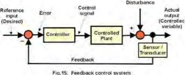
Figure 1.1: Basic closed-loop control system (Belwal, 2015)
Closed-loop control system have many advantages compared to open-loop control system. Some advantages of closed-loop control system:
i. Decreases system’s sensitivity to external disturbances. ii. Automatically adjusting the systems input to reduce errors. iii. Improves stability of a system.
iv. Manipulate the systems sensitivity.
v. Increase robustness of system against external disturbances. vi. Makes the performance more reliable and repeatable.
Basically, controller is needed for controlling a specific system which in this project is a machine tools. As the advantages of a closed-loop control system shown above, it is perfect fit machine tools. But, different machine tools will have different design of the control system. The design of the controller is playing an important role in order to achieve high performance. The type of controller could be linear or nonlinear depends on the condition of the machine tools will be working on. Both linear and nonlinear controller have their own pros and cons. For this project, a nonlinear controller will be designed with the addition of tracking differentiator to identify whether it can increase the tracking performance of the machine tools or will it be the other way around.
3
1.2Problem Statement
XY table ball-screw driven system is a type of machine tools that is actuated by AC servo drives. It has been widely used in many applications due to its low cost (Tao et al., 2006). These days, the usage of machine tools are in demand in the industrial sector as more innovative and complex products are being manufactured vary to the current technologies. As companies are fighting for the title “Best Manufacturer” and making more profits and less loss, their machine tools must robust and able to produce the products that meet the customer’s requirements and fast (accurate and high precision). Therefore, the control system of the machine tools is important in determining the performance of the machine tools. Several control system algorithm have been proposed and implemented in order for the machine tools to achieve “zero error” but it is impossible to achieve it. Thus, they are aiming to implement the best control system algorithm to the machine tools to reduce the error as possible and makes the system stable and run smoothly. This is important because in the manufacturing world, every second counts. In this case, a nonlinear PID (NPID) with integration of tracking differentiator (TD) module for tracking performance of machine tools will be simulated and analysed to see whether it is stable and suitable enough to be implemented to the industrial sector.
1.3Objectives
The objectives of this project are:
i. To design nonlinear PID (NPID) controller with the integration of tracking differentiator (TD) and without tracking differentiator.
ii. To compare the tracking performance of NPID controller with tracking differentiator and without tracking differentiator.
4
1.4Scope of Project
The scope of this project are:
i. The software used is MATLAB/Simulink version R2009b.
ii. The plant used is Googol Tech XY table ball screw drive system. iii. Only X-axis is considered.
iv. The frequency for the simulation and experiment is limited to 0.3 Hz and 0.5 Hz only.
1.5Report Structure
This report focuses on designing a nonlinear PID with integration of tracking differentiator (TD) module for tracking performance of machine tools. This report is divided into 5 major chapters which are introduction, literature review, methodology, result and discussions, and conclusion and recommendation. Chapter 1 discusses about the background of the project, problem statement, objectives, scope of project and the report structure.
Chapter 2 discusses about the literature review which includes the introduction, and other studies that relates to this project which are mechanical drive system, Proportional, Integral, Derivative (PID), Nonlinear Proportional, Integral, Derivative (NPID), Tracking Differentiator (TD), gap analysis and summary.
Chapter 3 discusses about the methodology used to fulfil the objectives and the scope of project. In this chapter, experimental setup, software requirement, system identification, flowchart which illustrates the project progress from the beginning through the end of the project and summary will be discussed.
Chapter 4 focuses on the discussion of all the data collected, response of the machine tools system analysis. Results obtained from the simulations and experimental work on NPID with TD module for tracking performance of machine tools were discussed thoroughly regarding the results and summary are also being discussed in this chapter.
5
CHAPTER 2
LITERATURE REVIEW
This chapter provides the past research on the motion control in machine tools, tracking performance of machine tools which are PID, Nonlinear PID (NPID), and Tracking Differentiator (TD). This section is divided into subsection in which section 2.2 discusses about state of the art on motion control in machine tools. Section 2.2.1 discusses about the mechanical drive system and section 2.2.2 is about disturbance in drive system. Tracking performance of machine tools is discussed in section 2.3. Section 2.3.1 discusses about the basic structure of PID controller, section 2.3.2 discusses about nonlinear PID, and section 2.3.3 discusses about the component that will be combined with nonlinear PID which is tracking differentiator (TD). Tracking differentiator is divided into two sections which are 2.3.3.1 for linear tracking differentiator and 2.3.3.2 for nonlinear tracking differentiator. Section 2.4 discusses about the gap analysis. Last but not least is the summary of the whole literature review.
2.1 Introduction
6
kp, integral gain, ki, differential gain, kd as it changes with error control. It is because nonlinear PID controller has advantages of rapidity, high precision and without overshoot, it can achieve good control effect (Zhang and Hu, 2012).
2.2 State of the Art of Motion Control in Machine Tools
Nowadays in the developing world of technologies, the mechanical drive system for machine tools also affected by the changes in technology. These technologies are implemented in the mechanical drive system in order to fulfil the demand for precision positioning and high speed of the system in the industry. The progression of the changes in mechanical drive system towards the latest technology has created a new challenge task to the control community with respect to compensate the disturbances in order to achieve better tracking performance (Jamaludin, 2008). Generally, this section will provide the chronological changes of the mechanical drive system and literature review on the disturbances in the drive system of the machine tools and controller design approach in order to achieve better tracking performance of the machine tools.
2.2.1 Mechanical Drive System
There are four types of mechanical drive system that is used in machine tools. The types are:
i. Rack and pinion drive system (RPD). ii. Direct drive linear drive system (DDL). iii. Ball screw drive system (BSD).
iv. Piezoelectric drive system.
7
[image:23.595.162.411.176.318.2]long travel distances (Ehrmann et al., 2016). According to Altintas et al. (2011), because of the low revolution in power transfer by the rack and pinion drive system, it produces high torque. Improvisation of the system is possible in terms of performance by designing it with clearance freedom and high torsional stiffness (Altintas et al., 2011).
Figure 2.1: Rack and pinion drive system (Dreyfusduke, 2015)
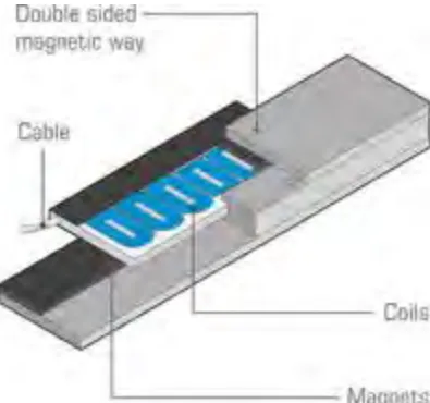
The second drive system is Direct Drive Linear drive system (DDL). The best explanation for direct drive linear drive system is there is no physical transmission between the motor and load (Chiew, 2013). It is a brushless servomotor and the needs of mechanical transmission elements such as timing belts, leadscrews, and rack and pinion were eliminated by the direct coupling of the payload to the motor’s moving part. Generally, direct drive linear drive system consists of lamination stacks, coils and magnets while the type of motor associates with the direct drive is the special class of synchronous brushless servomotor as shown in figure 2.2 and 2.3 (Anonymous, 2011). The technology used in the direct drive linear is intrinsic to a linear motor based system that makes it efficient and effective gearless assembly. There are two parts of the direct drive linear which are the coil assembly (primary part) and permanent magnet assembly (secondary part). Both parts are interacted through electromagnetic and the electrical energy is converted into linear mechanical energy with a high level of efficiency. This makes the drive system a better choice for precision. The positioning error will reduce to small value when a motor uses gears, chains or belts. Otherwise the more there are, the greater the errors (Barett, 2014). The design of the linear motor is specified to produce high force at low speeds or even when not in any kind of motion (static). The size is not based on power but purely on force what makes it different from the traditional drives.
Pinion
Linear pitch
Circular pitch
8
Figure 2.2: Iron-core linear drive system (Anonymous, 2011)
Figure 2.3: Ironless linear drive system (Anonymous, 2011)
[image:24.595.206.404.300.485.2]