Parallel Interference Cancellation Based Turbo
Space-Time Equalization in the SDMA Uplink
Andreas Wolfgang, Sheng Chen, Lajos Hanzo
Abstract— A novel Parallel Interference Cancellation (PIC) based turbo Space Time Equalizer (STE) structure designed for multiple antenna assisted uplink receivers is introduced. The proposed receiver structure allows the employment of non-linear type of detectors such as the Bayesian Decision Feedback (DF) assisted turbo STE or the Maximum Aposteriori (MAP) STE, while operating at a moderate computational cost. Receivers based on the proposed structure outperform the linear turbo detector benchmarker based on the Minimum Mean-Squared Error (MMSE) criterion, even if the latter aims for jointly detecting all transmitters’ signals. Additionally the PIC based receiver is capable of equalizing non-linear binary pre-coded channels. The performance difference between the presented algorithms is discussed using Extrinsic Information Transfer-function (EXIT) charts.
Index Terms— PIC, EXIT chart, precoding, Bayesian, STE.
I. INTRODUCTION
T
URBO equalization, which was first introduced in [1], has been the subject of intensive research efforts and many of the different algorithms originally developed for single-user equalization [2] [3] have been extended to multi-user models either in the form of turbo Multi-User Detec-tors (MUDs) designed for Code Division Multiple Access (CDMA) systems [4], for Multiple-Input Multiple-Output (MIMO) receivers [5] or for Space Division Multiple Access (SDMA) systems [6]. The extension from single-user to ei-ther multi-user equalization or to multiple transmit-antenna equalization imposes an increased computational complexity. Therefore the joint detection of signals arriving from mul-tiple transmitters has mostly been considered in the context of moderate-complexity linear detection techniques, such as for example Minimum Mean Squared Error (MMSE) filter-ing. Employing joint Maximum Likelihood (ML) rather than MMSE detection as for example proposed in [5], where a Maximum Aposteriori (MAP) STE was introduced, renders the receiver excessively complex, since its complexity in-creases exponentially both with the number of transmitters that have to be detected as well as with the Channel Impulse Response (CIR) length. A range of different methods have been developed for reducing the complexity of the ML de-tector, such as for example sphere decoding [7] or channelManuscript received May 10, 2005; revised May 20, 2006; accepted May 29, 2006. The associate editor coordinating the review of this paper and approving it for publication was J. Evans. The financial support of the EU under the auspices of the Phoenix and Newcom projects is gratefully acknowledged. The authors are also grateful to their colleagues for the enlightenment gained within the Phoenix consortium.
The authors are with the School of ECS, University of Southampton, SO17 1BJ, UK (email:{aw03r, sqc, lh}@ecs.soton.ac.uk).
Digital Object Identifier 10.1109/TWC.2007.05344.
shortening [8]. However, these techniques have mostly been applied in systems, where the number of receive antennas is equal or higher than the number of transmit antennas and they have been designed for channels having a linearly separable output, rather than for channels, which may have been exposed also to non-linear power amplifier impairments [9].
In contrast to joint detection, a different set of STE tech-niques, which are also reminiscent of the linear turbo detectors designed for detecting the signals arriving from multiple trans-mitters, is constituted by the family of so-called Interference Cancellation (IC) based schemes [4]. These IC schemes may be implemented either in a Successive (SIC) or a Parallel (PIC) fashion [10] [11]. In this paper we use the latter version.
Against this background, the novelty of this contribution is that the PIC based turbo receiver proposed in this paper decomposes the detection into two components, namely the linear, low complexity cancellation of the Multiple Access Interference (MAI) and the proposed iterative non-linear or classification based removal of the channel-induced Inter Sym-bol Interference (ISI). The proposed combination of PIC and non-linear channel equalization is capable of outperforming the MMSE based joint detection of all transmit antennas’ signals in the system, at the cost of a moderate complexity increase, as it will be shown in this contribution. A further advantage of the advocated structure is that it is capable of detecting signals, which have been distorted for example by power-efficient class AB amplifiers imposing non-linear distortions [9]. Furthermore, non-linear channels are also encountered for example, if binary precoding [12] is employed for efficiently spreading the extrinsic information across the transmitted sequence, which can be exploited by the receiver in terms of a substantial iteration gain.
The remainder of the paper is organized as follows. In Section II we will present our system model, which is used in Section III to briefly introduce three different joint detection strategies, namely the MMSE, the Decision Feedback (DF) assisted Bayesian and the MAP STE. In Section IV we will further develop our system model for the sake of deriving a PIC based non-linear detector, while we investigate the achiev-able performance of the different schemes in Section V using Extrinsic Information Transfer-function (EXIT) charts [13] as well as Bit Error Rate (BER) simulations. In Section VI we offer our conclusions.
II. SYSTEMMODEL
The system considered consists ofKnumber of mobile sta-tions (MSs) each employing anNTx-element transmit antenna array and a Base Station (BS) receiver, which hasNRxnumber
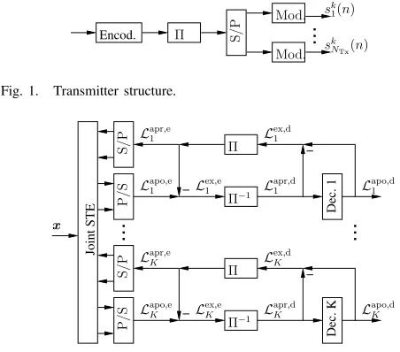
of Antenna Elements (AEs). The MSs’ transmitters illustrated in Figure 1 encode the source bits employing a convolutional encoder and interleave the resultant coded bits with the aid of a random interleaver. The encoded and interleaved bits are then mapped to theNTx different transmit antennas and modulated. The mapped symbols are transmitted to the BS over a frequency selective fading channel having a symbol-spaced CIR.
Given the transmitted symbols(ık)(n), which is associated with thekth MS’s transmit AEı, the output signal of the jth
AE of the BS receiver at time instantncan be written as1
xj(n) =
K
k=1
NTx
ı=1
L−1
l=0 h(k)
jı,ls(ık)(n−l) +ηj(n), (1)
where h(jı,lk) is the complex-valued channel gain of the lth
multi-path component of the channel between thekth MS’s AE ı and the jth BS receiver AE. Furthermore, L is the number of symbol-spaced multi-path components andηj(n)is the complex-valued Additive White Gaussian Noise (AWGN) having a variance ofE|ηj(n)|2= 2σ2
n.
Assuming that all MSs transmit at an identical power, the resultant Eb
N0 value for sourcek and code-rateRis given as
Eb
N0 =
1
R
NRx
j=1
L−1
l=0 E
|h(k)
jı,l|2
2σ2
nNRxlog2(M)
, (2)
whereMis the number of modulation levels used. In the case of finite length STEs such as the MMSE or the Bayesian STE, each of the BS receiver’s AEs in Equation (1) is followed by a tapped delay line of lengthM, which is also referred to as the feed-forward section of the STE. In vectorial notation, the delayed versions of the channel’s output can then be expressed by the super-vector2 x(n) =x(n)T, . . . ,x(n−M+ 1)TT,
where x(n) is a column vector hosting the NRx number of AE output signalsxj(n)given in Equation (1).3
Under the assumption of perfectly synchronized transmitters the relation between the signal transmitted by the MSs’ AEs and the channel’s output for channel tap l is described by a(NRx×KNTx)-dimensional matrix Hl, where the(j,(k− 1)NTx+ı)thelement of the matrix is given byh(k)
jı,l. The
super-matrixH representing the total system can then be obtained by concatenating the (NRx×KNTx)-dimensional matricesHl, yielding:
H=
⎛ ⎜ ⎝
H0 · · · HL−1 0 · · · 0
. .. . ..
0 · · · 0 H0 · · · HL−1
⎞ ⎟ ⎠.
1Note, that the indicesıandjare associated with the transmit and receive AE respectively, whereas the indices i and j are used as running indices defined in the context where they occur.
2All vectors and matrices are printed in italic bold fonts, super-vectors and super-matrices are printed in bold letters.
3For the MAP STE we may writex(n) =x(n), since no tapped delay line is used.
Encod. Π S/P
Mod.
Mod. s
k NTx(n) sk
[image:2.567.289.515.53.252.2]1(n)
Fig. 1. Transmitter structure.
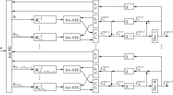
Dec. 1
Joint STE
Dec. K
−
− −
− Lapo1 ,d
Lapr,e
1
Π
Π−1
Lex,d
1
S/P
P/S
x
Lapo,d
K
Lapr,e
K
Π
Π−1
Lex,d
K
Lapr,d
K
S/P
P/S
Lapr,d
1
Lex,e
1
Lex,e
K
Lapo,e
K
Lapo,e
1
Fig. 2. Joint turbo STE receiver.
The channel output vectorx(n)can now be expressed as
x(n) = Hs(n)T, . . . ,s(n−M−L+ 2)TT +η(n)T, . . . ,η(n−M + 1)TT = Hs(n) +η(n)
= x(n) +η(n), (3) where the column vector
s(n) =
s(1)
1 (n). . . , s (1)
NTx(n), . . . , s
(K)
1 (n). . . , s (K)
NTx(n) T
contains the symbols transmitted by the K MSs’ AEs and η(n) = [η1(n), . . . , ηNRx(n)]T. For the derivation of the algorithms presented in this paper it is not relevant whether the interference experienced by a signal is caused by an AE of the same user or by the signals transmitted of other users. In order to keep the notation simple we therefore introduce the indexq= (k−1)NTx+ı, which ranges from1toQ, where
Q = KNTx is total number of AEs in the system. We can now rewrite the signal vector containing all sq(n)as s(n) =
s1(n). . . , sNTx(n), . . . , s(K−1)NTx+1(n), . . . , sKNTx(n)T. III. JOINTDETECTION
[image:2.567.51.254.632.678.2]The joint turbo detection scheme used is depicted in Figure 2. In the context of turbo detection the informa-tion generated by the different receiver components is ex-changed between them in the form of Log Likelihood Ratios (LLRs), which are defined as L(sq(n)|x(n)) = log
P(sq(n)=+1|x(n))
P(sq(n)=−1|x(n))
. In our further discussions the time index n is neglected for notational simplicity and we define
Lq = Lq,n = L(sq(n)|x(n)). Considering now the joint detection of allQAEs’ signals, the detector first performs soft detection of the received signal vector x(n) and returns the aposteriori LLR of the interleaved channel coded bits Lapoq ,e, as seen in Figure 2, where the superscript e represents the STE. The apriori LLRLaprq ,egenerated from the extrinsic LLR
Lex,d
q by the interleaverΠof Figure 2 is then removed from the
aposteriori LLR, resulting in the extrinsic information Lex,e
q ,
which is passed through the deinterleavers denoted by Π−1
carry out a soft decision using the deinterleaved extrinsic information provided by the STE as apriori informationLapr,d
q ,
where the superscript d denotes the channel decoder. After
convolutional decoding the decoders calculate the aposteriori LLRLapo,d
q of the coded symbols and subtract the apriori LLR
Lapr,d
q in order to obtain the extrinsic information Lexq ,d, as
seen in Figure 2. The extrinsic information of all decoders is interleaved again and used by the STE as apriori information
Lapr,e
q for the next iteration. In the first iteration the STE
assumes identical apriori probabilities for all bits of all users, yielding Lapr,e
q = 0 for all transmitters. For a more detailed
description of turbo-equalization the interested readers are referred to [2] [14].
A. MMSE Joint Detection
Linear MMSE criterion based joint turbo detection has been introduced in [4] and has been applied to SDMA systems in [6]. The proposed detector successively removes all MAI and ISI based on the extrinsic information obtained from the channel decoders. The MMSE based detector has the draw-back that the first iteration might be of relatively poor quality and therefore a sufficiently strong channel code has to be used for the sake of avoiding error-propagation amongst different users. The employment of a decision feedback structure as a solution to the problem of having a poor first-iteration performance was shown to be counter-productive [3] due to the sensitivity of the MMSE receiver to error propagation induced by the feedback structure in the context of single user turbo equalization. Hence, in this paper we will use the MMSE-based SDMA turbo-STE proposed in [6] as our reference receiver and refrain from using a DFE structure.
B. Bayesian Decision Feedback Aided Joint Detection
In contrast to MMSE-based turbo detectors, Bayesian STEs have been shown to be robust against error propagation [15] and thus are expected to perform well in decision feedback aided turbo detection. In this section we therefore first intro-duce a decision feedback structure, which will be employed by the Bayesian turbo STE. In addition to the feed-forward section of lengthM, the DF-STE is then characterized by the decision delayΔand the decision feedback orderN. Note that the oldest symbol vector, which still influences the detected symbol s˜q(n−Δ) is s(n−M −L+ 2). Furthermore, the oldest feedback symbol vector iss(n−Δ−N). Without loss of generality we therefore chooseN =M+L−2−Δfor the derivation of the proposed DF-STE. In order to describe the feedback structure, we first decompose the system matrix H into two sub-matricesH= [H1H2], whereH1hosts the first Q(Δ + 1) columns of H, while H2 represents the last QN
columns ofH. The channel’s output, which is identical to the input of the STE’s feed-forward filter can then be written as
x(n) =H1s1(n) +H2s2(n) +η(n), (4) where s1(n) =
s(n)T. . .s(n−Δ)TT represents the sym-bols in the feed-forward shift register, while s2(n) =
s(n−Δ−1)T. . .s(n−Δ−N)TT denotes the symbols in
the feedback register. Under the assumption that the detected feedback vector is correct, Equation (4) can be re-written as
r(n) =x(n)−H2˜s2(n) =H1s1(n) +η(n), (5) where r(n) is the reduced-size observation space created by removing the channel output states based on the already decided bits, as a benefit of using decision feedback [2]. For the remainder of this subsection let us now assume that the transmitted signals sq(n) are Binary Phase Shift Keying (BPSK) modulated. For a given feedback vector the possible noise-free channel output states in the new observation space
r(n) may then assume Ns = 2Q(Δ+1) different values,
depending on the transmitted symbol vectors(i), 1≤i≤Ns,
yielding r(i)=H1s(1i). The set of all possible desired output states in the translated decision spacer(n)can be partitioned into two subsets, namely into R±q, depending on the binary value of the transmitted BPSK symbol sq(n−Δ), which is associated with the kth user’s ıth transmit AE, i.e from AE q= (k−1)NTx+ı, as
R±q =
r(i,±)
q =H1s(1i) if s(qi)(n−Δ) =±1
, (6)
wheres(qi)is the element ofs1(i), which corresponds tosq(n− Δ). Based on the space translation formulated in Equation (5), the aposteriori LLRs associated with theqthAE in the system at the output of the joint Bayesian DF-STE may be written as
Lapo,e
q = log
P(sq(n−Δ) = +1|r(n))
P(sq(n−Δ) =−1|r(n))
= log
⎛ ⎜ ⎜ ⎜ ⎜ ⎜ ⎜ ⎝
r(i,+) q ∈R+q
p(i,+)e−||r(n)−r
(i,+) q ||2 2σ2
r(i,−) q ∈R−q
p(i,−)e−||r(n)−r
(i,−) q ||2 2σ2
⎞ ⎟ ⎟ ⎟ ⎟ ⎟ ⎟ ⎠
,
where rq,±i ∈ Rq,±, p(i,+) and p(i,−) are the a-priori
prob-abilities of r(qi,+) andr(qi,−), respectively. Assuming that the symbols in the sequences(i) = [(s(i)
1 )TsT2]T are statistically
independent of each other, the apriori probability of the channel stater(i) can be obtained from the apriori bit LLRs
as follows:
P(r(i)) = P(s(i)(n)) =
Q
q=1
M+L−2
j=0
eLaprq,n,−ej/2
1 +eLaprq,n,−eje
s(i)
q (n−j)Laprq,n,−ej/2,
whereLaprq,n−j,e is the apriori information of the bit associated with the qth AE at time instant (n−j) and s(i)
q (n−j)
is associated with the symbols in the sequence s(i) defined
in the context of Equation (6). Depending on the sign of
s(i)
q (n −Δ), P(r(i)) corresponds to p(i,+) or p(i,−). The
C. MAP STE
Both the MMSE and the Bayesian STE are finite length filters, i.e. they only use a finite observation of the received signal for the detection of each symbol. The optimum STE however invokes all the possible transmitted symbol sequences in order to make a MAP decision upon the transmitted symbol sequence. The MAP STE may be implemented using the Bahl-Cocke-Jelinek-Raviv (BCJR) algorithm [16], where the trellis states of the algorithm are jointly determined by the CIRs of theQdifferent AEs in the system.
The major advantage of the MAP-STE over the MMSE and Bayesian STE is that it can be readily combined with binary pre-coding at the transmitter side. It has been shown in [17] that the inner code of a turbo system, which is constituted by the wireless channel in our case, should be recursive in order to achieve large interleaving gains. The wireless channel described by Equation (1) is however a non-recursive structure. In [12] a simple binary transmit pre-coding scheme has been proposed, which renders the channel recursive without relying on the knowledge of the CIR. If binary pre-coding is used in conjunction with the transmitter structure considered, the pre-coder having the generator polynomial G(z) is inserted directly after the S/P converter in Figure 1. Under the assumption, that the pre-coder polynomial is shorter than the length of the CIR, the states of the MAP-STE trellis employed at the BS remain unchanged and only the transitions between the states have to be modified accordingly. It has been shown in [18] using a simple example that pre-coded MAP-STEs are capable of operating within 1 dB of the channel capacity.
IV. INTERFERENCECANCELLATIONBASEDDETECTION
In contrast to the joint detection strategy discussed in the previous section, another attractive design option to consider is the interference cancellation based turbo detection scheme illustrated in Figure 3. The philosophy of this scheme is based on the principle that with the aid of prefiltering, which is indicated asR−12
q in Figure 3 all theQ−1interfering uplink signals are considered to contribute additional white noise. The Single transmit Antenna element STE scheme represented by the acronym SA-STE in Figure 3 is then designed by ignoring the effects of MAI. This has the advantage that in contrast to the joint STE scheme of Figure 2, the complexity of the system no longer increases exponentially with the number of transmit AEs in the system, while still enabling us to use non-linear STE equalizers. The turbo STE section of the receiver seen in Figure 3 is identical to that in Figure 2, where the STE acts as a single-user STE or more precisely as a single transmit AE STE.
In order to describe the system mathematically, Equation (3) is rewritten as the sum of all AEs’ transmitted signals, yielding
x(n) =
Q
q
Hqsq(n) +η(n)
=
Q
q
xq(n) +η(n), (7)
where the (j, l)th element of the (NRx ×L)-dimensional
matrix Hq is given as h(jı,lk) with q = (k−1)NTx +ı. In
the proposed PIC scheme we now define the channel output generated by theqth AE as
xq(n) =xq(n) +
Q
i=q
xi(n) +η(n). (8) This yields a channel output after the PIC stage of Figure 3 at iterationj, which can be written as
˜
x(qj)(n) =xq(n)−
Q
i=q
Hi˜s(ij−1)(n), (9)
where we have ˜s(ij−1)(n) = [˜s(ij−1)(n). . .s˜(ij−1)(n−L+ 1)]T with˜s(ij−1)(n) = tanh(Lapoi ,d(n)/2)[3] being the vector containing the soft symbols associated with transmitteriafter the(j−1)stPIC iteration if the signals are BPSK modulated. In general the MAI may not be considered as Gaussian white noise because only a small fraction of the users may fall within the high-gain lobe of the antenna. Hence the covariance matrix of the noiseless interference experienced by the qth transmit
AE’s signal after the(j−1)th iteration is given as
R(MAIj) ,q(n) = E
⎛ ⎝Q
i=q
x(ij)(n)x(ij)(n)H
⎞ ⎠
=
Q
i=q
HiΛ(ij−1)(n)HHi , (10)
whereE(·)is the expection operator andΛi(n)is a diagonal matrix with diag
Λ(ij−1)(n)
= [1− |s˜(ij−1)(n)|2, . . . ,1− |s˜(ij−1)(n −L+ 1)|2]. For MAI contributions which may
not be considered as white noise, the matrixR(MAIj) ,q(n) will have non-zero off-diagonal elements. Taking into account the additional effects of the channel-induced white noise, the covariance matrix of the noise-contaminated MAI associated with theqth transmit AE may be written as
R(j)
q (n) =R(MAIj) ,q(n) + 2σn2INRx, (11) whereINRx is the (NRx×NRx)-dimensional identity matrix. The whitening of the signal after the soft PIC stage of Figure 3 can now be expressed as a matrix multiplication of the received signal vector ˜x(qj) with Rq(n)−12, which can be calculated using for example eigenvalue decomposition. Fol-lowing whitening, the resultant covariance matrix of the MAI plus noise term is equal to the identity matrix, which implies that the signal vector after whitening may be considered to be contaminated by white noise having unity variance.
The single-transmit AE STE indicated in Figure 3 as SA-STE now has to be designed for detection in the whitened signal space following the approach outlined in Section III. For the Bayesian STE outlined in Section III-B for example, we now define the set of legitimate output states as
R± q(n) =
r(i,±)
q = ˜H1,q(n)s1(i) if sq(n−Δ) =±1
,
whereH˜1,qis constructed using the whitened channel matrices
˜
Soft PIC
Dec. 1
SA−STE SA−STE
Dec. K
SA−STE SA−STE
−
−
− −
Π Π Π
˜
xNTx
˜ x1
x
Lapo,d
1
Lapr,e
1
Π
Π−1
Lex,d
1
S/P
P/S
S
/P
Lapr,e
K
Π−1 L apr,d
K
S/P
P/S
S
/P
˜
x(K−1)NTx+1
R−12
NTx
R−12
1
R−12
KNTx
Lex,d
K
Lapo,d
K
Lapr,d
1
˜
xKNTx
R−12
(K−1)NTx+1
Lex,e
1
Lapo,e
1
Lex,e
1
Lapo,e
[image:5.567.116.455.54.240.2]K
Fig. 3. PIC based turbo STE.
whitened signal space. The noise level considered by the SA-STE incorporated in the PIC scheme is now not 2σ2
n, but
simply unity, since the whitening filter has scaled the signal space accordingly. The operation of the PIC based turbo STE of Figure 3 may be summarized as follows. During the first iteration all interfering signals are considered to contribute additional noise, which is passed through a whitening filter to the SA-STE. The extrinsic information obtained by the equalizer is passed through a deinterleaver to the channel decoder, which uses it as apriori information. The extrinsic information of each channel decoder is passed back to the associated SA-STE of the same receiver chain and the resultant aposteriori information is passed back to the IC stage. The IC uses the aposteriori, rather than the extrinsic information of the channel decoders, since we assume the information obtained by the different users’ receiver chains to be independent of each other. The IC stage removes the remodulated and re-encoded soft information of the interfering transmitters and re-calculates the whitening filter matrices using Equations (10) and (11), taking into account the detected and removed MAI obtained in the previous iteration. The STE now uses the extrinsic information of the channel decoder. A new iteration of the PIC scheme is always based on two new inputs to the SA-STE, namely the input signal contaminated by less interference than in the previous iteration, and secondly, the extrinsic information provided by the channel decoder obtained in the previous iteration.
In order to comment on the associated implementational complexity related to the number of Add-Compare-Select (ACS) type trellis based operations used in systolic-arrays we simply quantify the number of trellis states. For BPSK modulated signals the full joint MAP detector is associated with 2Q(L−1), while the MAP STE employed by the PIC-aided detector has2L−1states, which result in 1 048 576 and
4 states in the case ofQ = 10 and L = 3 for the example used in Section V, plus the complexity of the linear PIC as estimated in [11].
A. Binary Pre-coding and PIC
In contrast to the non-precoded system, the outer channel decoder of a PIC based receiver employing binary pre-coding
does not directly return the symbols needed for interference cancellation in Equation (9). The MAP equalizer returns the non-precoded codeword LLRs Lapo,d
q (n), which are used by
the channel decoder for producing the corresponding LLR values for the non-precoded codeword bits. The PIC however needs a soft estimate of the precoded dataLapoq ,prec,d(n)bits, since the received channel outputs to be decontaminated are also precoded. For a pre-coder characterized by the polynomial
G(z) = 1 +z−1 these LLR values can be obtained as [19]
Lapo,prec,d
q (n) = log
1 +eLapoq ,d(n)eLapoq ,prec,d(n−1)
eLapo,d
q (n)+eLapoq ,prec,d(n−1)
(12)
where Lapo,prec,d
q (0) = Lapoq ,d(0). It can be observed that
the LLR values rapidly tend to zero, as the time index n increases, suggesting that no interference cancellation would be possible. To circumvent this problem, we generate the apri-ori LLRsLapr,prec,d
q (n) using the joint MMSE STE without
the assistance of apriori information, of Section III-A, which may be achieved at a low computational complexity. The non-precoded LLR values are then converted to non-precoded LLRs by adding these LLRs to the values seen in Equation (12) as follows:
Lapo,prec,d
q (n) = Laprq ,prec,d(n) +
log
1 +eLapoq ,d(n)eLapoq ,prec,d(n−1)
eLapo,d
q (n)+eLapoq ,prec,d(n−1)
which can now be used by the PIC described by Equation (9).
V. PERFORMANCEANALYSIS
10-4 10-3 10-2 10-1 100
2 3 4 5 6 7 8 9 10
BER
Eb/N0 [dB]
Joint MMSE PIC DF Bayesian PIC MAP Joint DF Bayesian Joint MAP Precoded MAP
Fig. 4. BER versusEb/N0performance after 6 turbo iterations for different joint and PIC assisted turbo STEs. The considered system was characterized byK = 2MSs, each using NTx= 2 transmit AEs and a BS employing
NRx= 2receive AEs. The feed-forward order of the MMSE and the DF Bayesian STE was chosen to beM= 2and the channel was assumed to be an equal-power two-tap channel. BPSK modulated signals were considered.
assumed to be an equal-power two-tap channel. The interleaver length was chosen to be 24 000 bits and the channel code considered was a Recursive Systematic Convolutional (RSC) punctured2/3-rate code.
The BER versus Eb/N0 performance recorded after six turbo iterations illustrated in Figure 4 shows that the MMSE based STE exhibits a poorer performance than the MAP and the DF Bayesian STE. Note that even though the DF Bayesian detector relies on hard decision feedback, this does not degrade its performance which is similar to that of the MAP STE. The precoded MAP STE employing a precoder polynomial of
(1 +z−1)is the only STE, which achieves an infinitesimally low BER. When comparing the performance of the joint detectors to that of the PIC aided detectors, it can be observed in Figure 4 that both the MAP PIC and the DF Bayesian PIC detector approach the performance of the joint detectors and clearly outperform the joint MMSE detector.
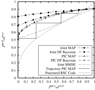
The reason why the PIC based detector is capable of outper-forming the joint MMSE detector can be found by considering the EXIT charts of the different STEs. The direct application of conventional EXIT chart analysis to the proposed PIC based detector is not straightforward, since the detector not only makes use of the extrinsic information provided by the RSC decoders, but also exploits their aposteriori information in order to improve the received signal quality. Nonetheless, it is feasible to generate EXIT charts, which assist us in understanding the convergence behavior of the receiver.4
The performance of the PIC based detector is evaluated us-ing the same system as used for generatus-ing Figure 4. Observe in the EXIT chart of Figure 5 recorded at Eb/N0 = 6 dB that the MAP PIC detector approaches the same performance as the joint detectors, although it commences its iterations from a lower initial mutual information than the corresponding
4This is because the EXIT charts of PIC based detectors are significantly more complex than those of the joint turbo detectors discussed in Section III. In fact, they would impose a similar complexity to that of full BER simulations.
0 0.1 0.2 0.3 0.4 0.5 0.6 0.7 0.8 0.9 1
0 0.1 0.2 0.3 0.4 0.5 0.6 0.7 0.8 0.9 1
I
apr,d
=
I
ex,e
Iapr,e=Iex,d
[image:6.567.314.513.53.241.2]Joint MAP Joint DF Bayesian PIC MAP PIC DF Bayesian Joint MMSE Trajectory PIC MAP Punctured RSC Code
Fig. 5. EXIT chart recorded atEb/N0 = 6dB for different STEs when considering a system characterized byK= 2 MSs, each usingNTx = 2
transmit AEs and a BS employingNRx= 2receive AEs. The channel was assumed to be an equal-power two-tap channel and BPSK modulated signals were considered.
joint detectors. The benefit of the PIC becomes clear, when comparing the MAP-PIC and the joint MMSE EXIT charac-teristics, where it can be observed in Figure 5 that both start at approximately the same initial mutual information, but the PIC based detector converges relatively fast even for a low initial input mutual information. This is due to the fact that even when the RSC channel decoders do not provide sufficiently reliable information for the STE, the soft information provided by the other STEs results in a rapid performance improvement. Furthermore, the decoder trajectory recorded for the iter-ative MAP PIC receiver characterized in Figure 5 sightly deviates from the performance expected on the basis of the transfer functions generated. This is due to the fact that when generating the EXIT charts with the aid of the proposed method, we assume that the extrinsic LLRsLexq ,e of the STE associated with different transmit AEs are independent of each other. However, this assumption has limited validity, because the transmit AEs’ LLRs become dependent on each other via Equation (9). During the first iterations, when the RSC decoders provide little extrinsic information, the information provided by the other STEs is particularly dominant and hence the mismatch between the predicted and true performance is more substantial. As the quality of the extrinsic information of the RSC decoders improves, their extrinsic information becomes the more dominant component of the aposteriori information. This means that we are beginning to feed back truly independent information and hence the theoretical as well as the true performance match. For the first iteration there is always a perfect match between the recorded trace and the transfer function.
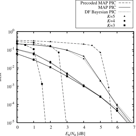
In order to investigate the performance of the precoded PIC aided STE let us now consider a system characterized byK= 3,4 and 5 MSs, each usingNTx= 2 transmit AEs and a BS employingNRx= 3receive AEs. The feed-forward order of the PIC based DF Bayesian STE was chosen to be M = 3
[image:6.567.38.269.54.234.2]10-5 10-4 10-3 10-2 10-1 100
0 1 2 3 4 5 6 7
BER
Eb/N0 [dB]
Precoded MAP PIC MAP PIC DF Bayesian PIC
K=5
K=4
[image:7.567.39.270.54.284.2]K=3
Fig. 6. BER versus Eb/N0 performance after 10 turbo iterations for a precoded PIC based STE as well as for a PIC aided MAP and a DF Bayesian STE. The considered system was characterized by K = 3,4and 5 MSs, each usingNTx= 2transmit AEs and a BS employingNRx= 3receive AEs. The feed-forward order of the PIC based DF Bayesian STE was chosen to beM = 3and the channel was assumed to be an equal-power three-tap channel. BPSK modulated signals were considered.
code employed was a 1/2-rate RSC code characterized by the octal generator polynomials of [6 5]. Note that for this system joint detection using the DF Bayesian or the MAP STE would be computationally demanding, since the number of states considered by the detectors is22·5·2 = 1 048 576,
whereas the corresponding PIC aided detectors only consider
22= 4states in each detection branch.
The BER versus Eb/N0 performance for the system con-sidered is shown in Figure 6, where it can be seen that both the MAP and the DF Bayesian PIC based STE exhibit a similar BER performance. An increased number of users only degrades the performance of the PIC based STE for low values ofEb/N0, while at higher values ofEb/N0the performance associated with3,4 and 5 MSs is similar. When considering the precoded MAP PIC detector using the precoder polynomial of (1 +z−1) it can be seen from Figure 6 that especially for K = 3 and 4 MSs the precoding significantly improves the performance compared to the non-precoded system. For
K= 5this performance advantage becomes less pronounced. The BER versus Eb/N0 performance of a 4QAM system is illustrated in Figure 7. The system was characterized by
K= 1,2and 3 MSs, each usingNTx= 2transmit AEs and a BS employingNRx= 4receive AEs. The feed-forward order of the joint MMSE STE was chosen to be M = 3 and the channel was assumed to be an equal-power three-tap channel while the interleaver had a length of 64 000 bits. The RSC code considered was again characterized by the octal generator polynomial of [6 5], while the precoded PIC aided MAP STE employed a precoder polynomial of (1 +z−2). Similarly to
Figure 6, it can be seen from Figure 7 that the advantage of the precoded PIC based STE over the joint MMSE iterative STE is larger for a lower number of transmitters, but it remains
10-5 10-4 10-3 10-2 10-1 100
-2 -1 0 1 2 3 4 5
BER
Eb/N0 [dB]
[image:7.567.297.531.55.233.2]Precoded PIC K=3 Precoded PIC K=2 Precoded PIC K=1 MMSE K=3 MMSE K=2 MMSE K=1
Fig. 7. BER versusEb/N0 performance after 10 turbo iterations for a precoded PIC based turbo STE as well as an iterative joint MMSE STE. The considered system was characterized by K= 1,2 and 3 MSs, each using
NTx = 2transmit AEs and a BS employing NRx = 4receive AEs. The feed-forward order of the joint MMSE STE was chosen to beM= 3and the channel was assumed to be an equal-power three-tap channel. 4QAM signals were considered.
0 0.1 0.2 0.3 0.4 0.5 0.6 0.7 0.8 0.9 1
0 0.1 0.2 0.3 0.4 0.5 0.6 0.7 0.8 0.9 1
I
apr,d
=
I
ex,e
Iapr,e=Iex,d
Precoded PIC-STE RSC code Trajectory
Fig. 8. EXIT chart recorded atEb/N0= 2dB for a precoded PIC based STE supportingK= 3MSs, each usingNTx= 2transmit AEs and a BS employingNRx= 4receive AEs. The channel was assumed to be an equal power three-tap channel and 4QAM signals were considered.
substantial.
This effect can be explained when considering the EXIT chart of the precoded PIC detector shown in Figure 8, which was recorded atEb/N0= 2dB for the same system parame-ters as used for generating Figure 7, while consideringK= 3
MSs. It can be observed that the precoded PIC aided STE reaches the point (1,1) in the EXIT chart, corresponding to an infinitesimally low BER. In contrast to the non-precoded EXIT functions of Figure 5, the precoded STE will always reach this point, regardless of the SNR. However, as the user load increases, the EXIT function of the associated detector generally becomes steeper. This implies that once the iterative detector has overcome the initial convergence threshold caused by the MAI, which is generally achieved at a relatively high
Eb/N0, its EXIT function terminates close to the point(1,1)
[image:7.567.311.513.321.508.2]high MAI the employment of a precoder might then even be a disadvantage, since it causes a further SNR degradation in addition to the MAI.
The EXIT-chart trace of the precoded MAP detector exhibits the same mismatch, as already observed in Figure 5 owing to the fact that the LLR values provided by the PIC detector are not sufficiently independent, which is also a consequence of using the approximate LLR value conversion proposed in Section IV-A.
VI. CONCLUSIONS
In this paper we derived a novel DF assisted Bayesian detector for SDMA uplink systems and presented a general PIC structure, which may be conveniently combined with any STE algorithm. The convergence behaviour of the PIC structure has been highlighted using EXIT chart analysis and the potential performance improvements achieved by precoded systems have been quantified. In our future work we will consider joint iterative channel estimation and turbo detection in the context of the proposed receiver structure in conjunction with asynchronous uplink transmissions.
REFERENCES
[1] C. Douillard, A. Picart, P. Didier, M. Jzquel, C. Berrou, and A. Glavieux, “Iterative correction of intersymbol interference: turbo-equalization,”
European Trans. Telecommun., vol. 6, no. 5, pp. 507 512., Sept.-Oct.
1995.
[2] L. Hanzo, C. H. Wong, and M. S. Yee,Adaptive Wireless Transceivers: Turbo-Coded, Turbo-Equalized and Space-Time Coded TDMA, CDMA,
and OFDM Systems. John Wiley and IEEE Press, Feb. 2002.
[3] M. Tuchler, R. Koetter, and A. Singer, “Turbo equalization: principles and new results,”IEEE Trans. Commun,, vol. 50, no. 5, pp. 754767, May 2002.
[4] X. Wang and H. Poor, “Iterative (turbo) soft interference cancellation and decoding for coded cdma,”IEEE Trans. Commun., vol. 47, no. 7, pp. 10461061, July 1999.
[5] A. Tonello, “MIMO MAP equalization and turbo decoding in interleaved space-time coded systems,”IEEE Trans. Commun., vol. 51, no. 2, pp. 155160, Feb. 2004.
[6] T. Abe and T. Matsumoto, “Space-time turbo equalization in frequency selective MIMO channels,”IEEE Trans. Veh. Technol., vol. 52, no. 3, pp. 469475, May 2003.
[7] H. Vikalo, B. Hassibi, and T. Kailath, “Iterative decoding for MIMO channels via modified sphere decoding,” IEEE Trans. Wireless Com-mun., vol. 3, no. 6, pp. 22992311, Nov. 2004.
[8] G. Bauch and N. Al-Dhahir, “Reduced-complexity space-time turbo equalization for frequency-selective mimo channels,”IEEE Trans.
Wire-less Commun., vol. 1, no. 4, pp. 819828, Oct. 2002.
[9] L. Hanzo, S. Ng, W. Webb, and T. Keller, Quadrature Amplitude Modulation: From Basics to Adaptive Trellis-Coded, Turbo-Equalised and Space-Time Coded OFDM, CDMA and MC-CDMA Systems, Second
Edition. John Wiley and IEEE Press, Sept. 2004.
[10] L. Hanzo, L.-L. Yang, E.-L. Kuan, and K. Yen, Single- and Multi-Carrier DS-CDMA: Multi-User Detection, Space-Time Spreading,
Syn-chronisation, Networking and Standards. John Wiley and IEEE Press,
Jan. 2003.
[11] L. Hanzo, M. M¨unster, B. Choi, and T. Keller,OFDM and MC-CDMA for Broadcasting Multi-User Communications, WLANs and Broadcast-ing. John Wiley and IEEE Press, July 2003.
[12] K. Narayanan, “Effect of precoding on the convergence of turbo equal-ization for partial response channels,”IEEE J. Sel. Areas in Commun., vol. 19, no. 4, pp. 686698, April 2001.
[13] S. ten Brink, “Convergence behavior of iteratively decoded parallel concatenated codes,” IEEE Trans. Commun., vol. 49, no. 10, pp. 17271737, Oct. 2001.
[14] L. Hanzo, T. Liew, and B. Yeap,Turbo Coding, Turbo Equalisation and
Space-Time Coding. John Wiley and IEEE Press, July 2002.
[15] A. Wolfgang, S. Chen, and L. Hanzo, “Radial basis function network assisted space-time equalisation for dispersive fading environments,”
IEE Electron. Lett., vol. 40, no. 16, pp. 10061007, July 2004.
[16] L. Bahl, J. Cocke, F. Jelinek, and J. Raviv, “Optimal decoding of linear codes for minimizing symbol error rate,”IEEE Trans. Inf. Theory, vol. 20, pp. 284287, Mar. 1974.
[17] S. Benedetto, D. Divsalar, G. Montorsi, and F. Pollara, “Serial concate-nation of interleaved codes: performance analysis, design, and iterative decoding,”IEEE Trans, Inf Theory, vol. 44, no. 3, pp. 909926, May 1998.
[18] Z. Zhang, T. Duman, and E. Kurtas, “Achievable information rates and coding for mimo systems over isi channels and frequency-selective fading channels,”IEEE Trans. Commun., vol. 52, no. 10, pp. 16981710, Oct. 2004.
[19] [19] J. Hagenauer, E. Offer, and L. Papke, “Iterative decoding of binary block and convolutional codes,”IEEE Trans. Inf. Theory, vol. 42, no. 2, pp. 429445, 1996.
Andreas Wolfgangwas born in Germany, in 1977. He received the Dipl. Ing. degree in electrical en-gineering from Karlsruhe University of Technol-ogy, Karlsruhe, Germany, in 2003, and is currently pursuing the Ph.D. degree at the University of Southampton, Southampton, U.K. His primary re-search interests include wideband communication systems, iterative detection as well as nonlinear signal processing.
Sheng Chen (M’90-SM’97) obtained a BEng. degree from the East China Petroleum Institute, Dongying, China, in 1982, and a Ph.D. degree from the City University, London, in 1986, both in control engineering. In 2005, he was awarded DSc from the University of Southampton, Southamptom, UK. Since 1999 he has been with the School of Electronics and Computer Science, the University of Southampton, UK. He previously held research and academic appointments at the Universities of Sheffield, Edinburgh and Portsmouth, all in UK. Professor Chen’s recent research works include adaptive signal processing, wireless communications, modelling and identification of nonlinear systems, neural network and machine learning, finite-precision digital controller design, evolutionary computation methods, and optimization. He has published over 280 research papers.
In the database of the world’s most highly cited researchers in various disciplines, compiled by Institute for Scientific Information (ISI) of the USA, Dr Chen is on the list of the highly cited researchers in the engineering category (see www.ISIHighlyCited.com).