INSTITUTE OFPHYSICSPUBLISHING JOURNAL OFMICROMECHANICS ANDMICROENGINEERING
J. Micromech. Microeng.16(2006) S54–S60 doi:10.1088/0960-1317/16/6/S09
Force feedback linearization for
higher-order electromechanical
sigma–delta modulators
Yufeng Dong, Michael Kraft and William Redman-White
University of Southampton, School of Electronics and Computer Science, Highfield, Southampton, SO17 1BJ, UK
E-mail:[email protected]
Received 30 November 2005, in final form 1 December 2005 Published 9 May 2006
Online atstacks.iop.org/JMM/16/S54
Abstract
A higher-order electromechanical sigma–delta modulator can greatly improve the signal-to-noise ratio compared with a second-order loop that only uses the sensing element as a loop filter. However, the electrostatic force feedback on the proof mass is inherently nonlinear, which will produce harmonics in the output spectrum and limits the total
signal-to-noise and distortion ratio. High performance inertial sensors, which use sigma–delta modulators as a closed-loop control system, have strict requirements on the output signal distortion. In this paper, nonlinear effects from the force feedback and pick-off circuits are analysed and a strategy for force feedback linearization is put forward which can considerably improve the signal-to-noise and distortion ratio. A PCB prototype of a fifth-order electromechanical modulator with a bulk micromachined accelerometer was used to demonstrate the concept.
(Some figures in this article are in colour only in the electronic version)
1. Introduction
In order to improve the linearity, bandwidth and dynamic range, micromachined inertial sensors usually operate in a closed loop. The prevailing technique is based on the principle of a sigma–delta modulator (M), which produces an intrinsically digital output. This approach is suitable for any MEMS sensors using capacitive signal sensing pick-off circuits, as sensing capacitors can be used for position measurement as well as an electrostatic actuator. Most of the electromechanicalMs reported in the literature to date are of second order [1,2], which only use the sensing element as the loop filter. TheM loop exhibits at best a second-order noise shaping due to very low dc gain at low frequencies of the mechanical integrator, which limits the signal-to-noise ratio (SNR) of the control system. Thus, adopting a higher-order M to increase the control system performance is a promising approach [3, 4]. The concepts for the control system topology are borrowed from the higher-order electronic M analog-to-digital converters (ADC). Using similar architectures of electronic M ADC, additional
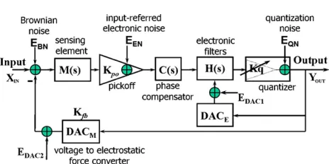
Figure 1.Generic diagram of a high-order electromechanical
M.
is used to generate the electrostatic force feedback on the proof mass. This is equivalent to a one-bit DAC providing the feedback signal in a continuous time M ADC. It is well known that a continuous-time M suffers from the non-idealities of the feedback DAC [5], such as clock jitter, DAC pulse shape (unequal rise and fall times) and excess loop delay (i.e., a delay that pushes the feedback pulse out of one clock cycle into the next). For the relatively narrow low frequency signal bandwidth of an electromechanical
M, usually the oversampling frequency is below 1 MHz. Therefore, the effect of clock jitter (typically smaller than 20 ps) is not as serious as in a continuous-time M ADC used for wideband communication applications [6], which usually operate between 10 MHz and a few GHz. Furthermore, most electromechanicalMs employ a return-to-zero (RTZ) force feedback DAC to eliminate any cross-talk effects between the feedback and the sensing phase [2]; this also ensures good immunity to unequal rise and fall times in the conversion from electrical voltage to mechanical force. In fact, the major advantage of a one-bit DAC in a continuous-time M ADC is its linearity; however, this is not true for an electromechanical one-bitM. In most analysis of closed-loop micromachined capacitive sensors, the residual motion x of the sensing element proof mass is neglected as it is far smaller than the nominal gap d0, and thus the
resulting nonlinear effect is not considered. This is not a valid assumption for high performance sensors [7–9]. This paper analyses the nonlinearities arising from the conversions between the mechanical and electrical domains in the feedback loop and the forward path. A linearization strategy is put forward to reduce the nonlinearity from electrostatic force feedback on the proof mass to improve the signal-to-noise-and-distortion ratio (SNDR).
2. Nonlinear electrostatic feedback force
A generic diagram of a high-order electromechanicalM is shown in figure1.M(s)represents the transfer function of the mechanical sensing element that converts the input inertial force signal into a displacement and inherently serves as a second-order low pass filter. EBN is the intrinsic noise due
to Brownian motion [2]. Kpo is the gain of the pick-off
interface that converts the displacement to a voltage. EEN
is the input-referred electronic noise of the pick-off interface.
C(s) is a lead compensator to supply the necessary phase margin to ensure stability of the closed-loop system. H (s)is the electronic filter to boost the noise shaping. The one-bit
YOUT(s)=
M(s)KpoC(s)H (s)Kq
1 +L(s) (XIN+EBN−EDAC2)
+H (s)Kq
1 +L(s)(EENC(s)+EDAC1)+
1 1 +L(s)EQN
=STF(s)(XIN+EBN−EDAC2)
+ ETF(s)(EENC(s)+EDAC1)+ QTF(s)EQN (1)
where L(s) = KfbM(s)KpoC(s)H (s)Kq, and M(s) is the
transfer function of the sensing element and is given by
M(s)= 1 ms2+bs+k.
STF(s),ETF(s)and QTF(s)are the signal, electronic noise and quantization noise transfer functions, respectively, and is given by
STF(s)=M(s)KpoC(s)H (s)Kq
1 +L(s)
ETF(s)= H (s)Kq
1 +L(s)
QTF(s)= 1
1 +L(s).
For an oversampling system, the signal band is at a relatively low frequency; thus equation (1) can be approximated by
YOUT(s)=
1
Kfb
(XIN+EBN−EDAC2)
+ 1
KfbM(s)Kpo
(EENC(s)+EDAC1)
+ 1
KfbM(s)KpoH (s)Kq
EQN. (2)
It can be seen from equation (2) that the electromechanical
M can shape the quantization noise EQN considerably,
depending on the oversampling frequency and the order of the loop filters. Furthermore, the noise sources EEN
and EDAC1 are also shaped; this is described in more
detail in [11]. However, the Brownian noiseEBN and the
electromechanical DAC errorEDAC2will not be shaped by the
M and thus add directly to the input of the sensor system. Therefore the electromechanical DAC errorEDAC2is critical
for the sensor system performance. The Brownian noise can be reduced only by mechanical structure optimization and packaging, and is not considered in the following analysis. A conventional electrostatic force feedback arrangement of an electromechanical M is shown in figure 2. For an ideal one-bit electronic DAC, there exists no DAC error due to its inherent linearity, but the conversion of a voltage to an electrostatic feedback force on the proof mass by the DACM
Y Donget al
[image:3.595.114.463.217.377.2]Figure 2.Conventional force feedback arrangement in electromechanicalM.
Figure 3.Systematic level model of a fifth-order electromechanicalM.
and is given by
Kfb=sgn(YOUT)
ε0AfbVfb2
2[d0+ sgn(YOUT)(x)]2
(3)
=sgn(YOUT)
K0
[1 + sgn(YOUT)(x/d0)]2
(4)
where K0 = ε0AfbVfb2
2d2
0 and denotes the gain of the
electrostatic feedback force without considering the residual proof mass motion. ε0 is the dielectric constant, Afb the
area of the feedback electrodes, Vfb the feedback voltage,
d0 is the nominal gap of the sensing capacitor and YOUT
the quantizer output, which is either a positive or negative reference voltage(Vref). The Taylor expansion of equation (4)
indicates that the feedback force has higher harmonic content relating to the residual motionx. Therefore, the harmonic distortion will lead to a reduction in the SNDR. To investigate the effects of the nonlinear feedback on electromechanical
Ms, a system level simulation was carried out for a fifth-order electromechanicalM as shown in figure3using a Matlab/Simulink Toolbox [12].
All simulations in this work used a sampling frequency
fs = 125 kHz and took into account the electronic thermal
noise from the pick-off interface assuming a power spectral density (PSD) of 10 nV Hz−1/2for the amplifier. The sensing
element has the following parameters: mass m = 9.7 mg, damping coefficientb=0.06 N m−1s−1and spring stiffness
k=48 N m−1; these are figures from a bulk-micromachined
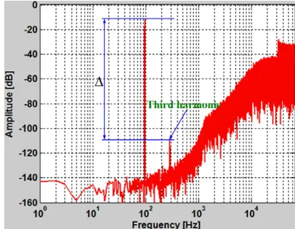
sensing element that was provided by QinetiQ for this work. The spectrum of the output bitstreamYOUTis plotted in figure4.
Obviously, there is a third harmonic distortion peak at three
Figure 4.The output spectrum of a fifth-order electromechanical
M with a conventional force feedback DAC.
times of the input signal frequency (assumed to be 96 Hz) which causes the SNDR to drop by about 20 dB in a 300 Hz signal bandwidth.
To derive an equation for the signal harmonics all noise sources in equation (1) are omitted. Due to the time-averaging characteristic of the electromechanicalM output bitstream, the time the top and bottom electrodes are energized is virtually identical, thus even harmonics are canceled. Neglecting the even term of equation (4), the system output can be approximated to
YOUT≈sgn(YOUT)
XIN
K0
1 +
x d0
2
[image:3.595.305.512.412.573.2]Figure 5.Variation of the feedback force magnitude due to residual proof mass motion.
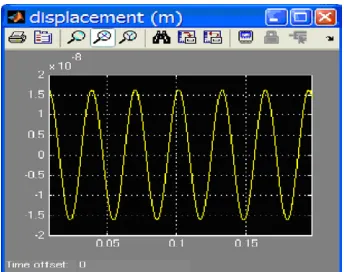
Figure 6.Residual proof mass displacement of a simulation run of the model in figure2.
Equation (5) denotes that the DACM only suffers from
the third harmonic distortion for a sinusoidal input signal. The amplitude difference between the output signal at the input force signal frequency and the third harmonic can be calculated by = 20 log[(x/d0)2] (dB). If the proof mass
motionxis assumed very small and its effect is neglected, the feedback force is a rectangular waveform with an amplitude of
K0(assumingVref=1 V). However, if the nonlinear feedback
effect is considered, the feedback force becomes nonlinear; this is shown in figure5.
The superimposed sinusoidal ripple on the upper and lower waveform edges in figure 5 has the same frequency as the input signal and its amplitude is given by 2(x/d0)K0
according to equation (3). The amplitude of the third harmonic is given by(x/d0)2K0. Assuming a 50% full scale input signal,
the maximum residual proof mass motionxis 0.016µm for a nominal gap ofd0=3µm; this is shown in figure6.
Therefore, an upper limit of the SNDR can be calculated by
SNDR= Psignal
Pnoise+Pdistortion
where
Psignal= fbw
−fbw
|STF(j2πf )PSD(XIN(j2πf ))|2df
the electrostatic force conversion in the signal bandwidth
fbw, respectively; PSD(XIN(j2πf )),PSD(EQN(j2πf ))and
PSD(EDAC1(j2πf )) and are the PSD of input signal,
quantization noise and distortion of electrostatic force conversion, respectively. For the parameters used in the simulations the SNDR was calculated to be about 90 dB. For high performance sensing elements with a lower spring constant the residual motion can be considerably higher; thus the maximum achievable SNDR without electrostatic force feedback linearization is even lower.
3. Feedback electrostatic force linearization
3.1. Linearized voltage to force conversion in the feedback loop
To circumvent the nonlinear effect due to the proof motion, it is necessary to linearize the conversion from voltage to electrostatic force. The feedback voltage is modified to be a function of the residual proof mass motion and is given by
Vfb∗=Vfb+ sgn(YOUT)· (7)
where = (x/d0)Vfb is the linearization factor. The
electrostatic force of equation (3) thus becomes
Kfb∗ =sgn(YOUT)
ε0Afb(Vfb+ sgn(YOUT)·)2
2(d0+ sgn(YOUT)·x)2
=sgn(YOUT)K0. (8)
It should be noted that the force magnitude in equation (8) is independent of the residual proof mass motion xand is equivalent toK0in equation (3). The modified feedback
arrangement of the electromechanical M is shown in figure7. The additional building blocks are an amplifier, an adder and a subtractor.
Using this force feedback linearization scheme, a simulation was carried out with the system model as shown in figure 3. The spectrum of the output bitstream is shown in figure 8, which has no third harmonic distortion peak. The SNDR improves about 20 dB due to the feedback force linearization.
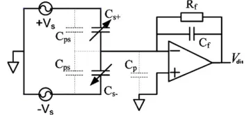
Typically, the pick-off interface is implemented with a charge amplifier as shown in figure 9. Assuming small deflectionsx, j ωRfCf 1 andCf =2Cs [13], the output
of the amplifier is given by
Vdis≈ −(x/d0)×Vs (9)
whereVsis the amplitude of the high frequency carrier voltage.
The linearization factor introduced in the previous section can be expressed as
=(x/d0)Vfb=Vdis×(−Vfb/Vs)=Vdis×KL (10)
KL= −Vfb/Vs (11)
where KL is the gain of the linearization amplifier in the
[image:4.595.80.252.303.439.2]Y Donget al
[image:5.595.309.506.202.358.2]Figure 7.The modified electrostatic force feedback arrangement of the electromechanicalM.
Figure 8.The output spectrum of a fifth-order electromechanical
[image:5.595.64.269.208.373.2]M with a linear feedback force DAC.
Figure 9.A charge amplifier is used for the pick-off interface.
3.2. Nonlinear displacement to voltage conversion in the forward path
For high performance sensors, the nonlinear conversion from the sensor motion to voltage of the pick-off interface should be considered. Considering the effect of the residual motion on the transfer function of the pick-off circuit, its output voltage is changed from equation (9) to
Vdis≈ −(x/d0)×Vs×[1−(x/d0)2]−1. (12)
Combining equations (3), (8) and (12), the electrostatic feedback force conversion factor can be rewritten as
Kfb∗∗=sgn(YOUT)K0×
d0+ sgn(YOUT)x[1−(x/d0)2]−1
d0+ sgn(YOUT)x
2
.
(13)
[image:5.595.305.514.402.562.2]Equation (13) indicates that the electrostatic force is still a function of the residual motion due to the nonlinear pick-off circuit in the forward path. The feedback force for the three discussed cases (equations (3), (8) and (13)) are plotted
Figure 10.Feedback nonlinearity on the electromechanical DAC waveform with different feedback loop linearization.
Figure 11.M spectrum of the output bitstream with a linear feedback DAC and considering the nonlinearity of the pick-off interface.
in figure 10 with d0 = 3 µm. The ideal feedback force
[image:5.595.76.253.414.497.2]Figure 12.Two separate sets of capacitors for electrostatic force feedback and sensing.
Figure 13.Control sequence for electrostatic force feedback and one-bit electronic DAC in the loop of a fifth-order
electromechanicalM.
shows a simulation result considering the nonlinearity of the pick-off amplifier in the forward path, the effect of the third harmonic distortion is still visible but considerably reduced.
4. Experimental results
A PCB prototype was built to demonstrate the modified feedback strategy. The capacitor electrode arrangement is shown in figure 12, which use two separate sets of comb capacitors for sensing and feedback control. To avoid feedback cross-talk effects on the sensor output, the electrostatic feedback force electrodes are grounded during the sensing phase [2].
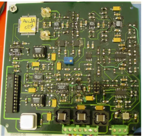
Figure13shows the control sequence for the voltage to feedback force DAC. analog switches S1, S2, S3 and S4 are the control switches for the force feedback on the sensing element, which implements the electromechanical DAC with a RTZ timing control. Signals INA is the M output bitstream and CLKO is the sampling clock with a frequency of 125 kHz. CLK is the master clock. The ratio of feedback time to sampling cycle is 75%, and this leaves 2 µs for the sensing phase. The analog switches are high speed and low charge injection with break-before-make switching (ADG441). Most components of the four-layer PCB are in surface mount technology (SMT) packages, which lead to low noise and small size. The PCB also comprises the micromachined accelerometer and is shown in figure14. It was mounted onto a permanent magnet vibration system. A spectrum analyser (Advantest, R9211B) is used to measure the spectrum of the output bitstream. The spectrum noise floor is measured about−110 dB as shown in figure15. Using the linearization scheme discussed above, there is no trace of the signal harmonic in the output spectrum in response to an input of sinusoidal vibration with the amplitude 0.1 g and frequency 100 Hz. The measurement result is shown in figure16.
[image:6.595.293.527.340.510.2]Figure 14.PCB of a fifth-order electromechanicalM with the linearized electrostatic force feedback.
Figure 15.Noise floor of the output bitstream spectrum of the prototype of figure14.
[image:6.595.292.527.556.726.2]Y Donget al
5. Conclusions
In this paper, the nonlinearity generated by the electromechanical DAC in the feedback loop and the conversion from displacement to voltage in the forward path has been analysed. An effective linearization scheme is proposed to increase the SNDR. The nonlinearity in the forward path is considerably less significant than that of in the feedback loop. The experimental results based on PCB prototype agree well with the simulation prediction. The force feedback linearization will be useful for high performance sensors.
Acknowledgments
The authors would like to thank Mr D O King at Qinetiq for supplying the micromachined accelerometer.
References
[1] Amini B V, Pourkamali S and Ayazi F 2004 A 2.5 V 14 bit sigma-delta CMOS-SOI capacitive accelerometerISSCC 2004: Tech. Dig. IEEE Int. Solid-State Circuits Conf. (CA) pp 314–5
[2] Lemkin M and Boser B E 1999 A three-axis micromachined accelerometer with a CMOS position-sense interface and digital offset-trim electronicsIEEE J. Solid-State Circuits34456–68
[3] Petkov V P and Boser B E 2005 A fourth-orderσ interface for micromachined inertial sensorsIEEE J. Solid-State Circuits401602–9
[4] Dong Y, Kraft M, Gollasch C and Redman-White W 2005 A high-performance accelerometer with a fifth-order sigma-delta modulatorJ. Micromech. Microeng.
15S22–9
[5] Breems L and Huijsing J H 2001Continuous-Time Sigma-Delta Modulation for A/D Conversion in Radio Receivers(Dordrecht: Kluwer)
[6] Yan S and Snchez-Sinencio E 2004 A continuous-timeσ
modulator with 88-dB dynamic range and 1.1-mHz signal bandwidth IEEE J. Solid-State Circuits 3975–86
[7] Tay F, Xu J and Logeeswaran V J 2000 A differential capacitive low-g microaccelerometer with mg resolution Sensors Actuators 86 45–51
[8] Yazdi N, Ayazi F and Najafi K 1998 Micromachined inertial sensorsProc. IEEE861640–59
[9] Chae J, Kulah H and Najafi K 2004 An in-plane
high-sensitivity, low-noise micro-g silicon accelerometer with CMOS readout circuitryJ. Microelectromech. Syst.
13628–35
[10] Schreier R 1993 An empirical study of high-order single-bit delta-sigma modulatorsIEEE Trans. Circuits Syst. II40461–6
[11] Dong Y, Kraft M and Redman-White W 2005 Noise analysis for high order electromechanical sigma-delta modulators ADDA 2005: Proc. 5th Int. Conf. Advanced A/D and D/A Conversion Techniques and Their Applications (Ireland) pp 147–52
[12] Fornasari A, Malcovati P and Maloberti F 2005 Improved modeling of sigma-delta modulator non-idealities in SimulinkISCAS 2005: IEEE Int. Symp. Circuits and Systemsvol 6 pp 5982–5
[13] Loetters J C, Olthuis W, Veltink P H and Bergveld P 1999 A sensitive differential capacitance to voltage converter for sensor applicationsIEEE Trans. Instrum. Meas.