Article
Multi-Point Collaborative Authentication Method
Based on User Image Intelligent Collection in the
Internet of Things
Yunfa Li1,* , Yifei Tu1 and Jiawa Lu2
1 Key Laboratory of Complex Systems Modeling and Simulation, School of Computer Science and Technology, Hangzhou Dianzi University, Hangzhou 310018, China
2 Department of Mechanical, Materials and Manufacturing Engineering, Faculty of Science and Engineering, University of Nottingham Ningbo China, Ningbo 315100, China
* Correspondence: [email protected]
Received: 26 July 2019; Accepted: 28 August 2019; Published: 2 September 2019
Abstract: With the increasing demand for intelligent services of the Internet of Things (IoT), its security issues have attracted widespread attention recently. Since most of the existing identity authentication policies are based on a single authentication mode, they are highly likely to cause problems such as illegal operation and stealing of sensor information. In order to meet the needs of increasing IoT users for the security management of intelligent services, a multi-point collaborative authentication method based on user image intelligent collection for the security problems faced by IoT in identity authentication is proposed in the paper. This method firstly collects the identity of the legal user through the intelligent collection technology and then realizes the identity authentication of the unidentified user through the collaborative authentication between the local domain management machine, the back-end image management machine, and the cloud server. Compared with the traditional single identity authentication method, our method uses three-party collaborative authentication to avoid the problem of sensor information stealing easily caused by a single authentication method, which makes the user’s identity authentication more secure and effective. The security analysis shows that the method is able to resist multiple attacks and prevent the sensor information from being illegally operated and stolen, protecting the security of the sensor information.
Keywords:Internet of Things; identity authentication; collaborative authentication; security
1. Introduction
With the continuous development of technology, the development of the Internet of Things (IoT) has shown an exponential growth. Combining sensor technology, Internet technology, and wireless technology, IoT realizes real-time interaction between the virtual network and the real world. It senses and collects data in real time through a large number of sensors and transmits data to the server for data calculation and processing. In addition, the processed information is transmitted to the user. IoT has unlimited application prospects and is currently widely used in smart homes, wearable devices, implantable devices, medical devices, connected cars, and transportation systems. Therefore, the Internet of Everything has become an inevitable trend in technology development and industrial application. Although IoT has greatly improved the level of intelligence and automation of society, the information transmitted wirelessly and exposed to the public is highly likely to be tampered with, stolen, and interfered. Therefore, the security of the IoT system has been greatly threatened. Incidents caused by IoT security occur frequently in the real world, and their influence and destructive power are extremely great, so that IoT security has already become a topic of global
concern. The issue of IoT security is the primary problem solved by the development of IoT. With the increasing attention paid to IoT data security, a secure and effective identity authentication protocol has become an important requirement for the rapid development of IoT.
IoT identity authentication is threatened by the following major aspects in terms of security. (1) Denial of service (DoS) attacks: When the data are transmitted, the data transmission of a large number of machines may cause network congestion, because IoT has a large number of nodes and exists in a cluster. The attacker may broadcast invalid information to perform a consumptive attack on the network bandwidth, so that the request of the legal user cannot be executed. (2) Node attack: There is a large number of sensing nodes in the IoT application, most of which are deployed in unattended scenarios. Attackers can easily destroy these nodes and impersonate legitimate nodes. Therefore, there will be a large number of damaged nodes and malicious nodes in the IoT. (3) Replay attack: The attacker can deceive the IoT system to obtain an authenticated identity by sending a packet when the destination host has accepted. (4) Eavesdropping and camouflage attacks: The attacker steals security information from a common channel and falsifies other users’ information through known security information. In order to solve these problems and protect the security of identity authentication, this paper proposes a multi-point collaborative authentication method based on user image intelligent collection in the IoT. Firstly, the intelligent collection technology is used to realize the image identity collection of legal users, that is the image information of the legal user is collected by the camera and stored in the database of the local domain management machine, the back-end image management machine, and the cloud server. Secondly, the camera is used to collect the unidentified user image information, which was transmitted to the three databases, as well. Thirdly, the legal user image information and the unidentified user image information in the three databases are compared to realize the identity authentication of the unidentified user, respectively. Not covering the field of imagery, the limitation of our method is that it just compares the image of the legal user with the that of the unidentified user, so there is no algorithm for the image in our method. The security analysis shows that the method is able to resist multiple attacks and prevent the sensor information from being illegally operated and stolen, protecting the security of the sensor information.
2. Related Work
With the rapid development of IoT technology, secure identity authentication has become the focus of research for IoT security in the recent years.
proposed an authentication and session key agreement method, a data encryption method, and a data integrity check method in order to solve the confidentiality, integrity, and usability problems in the face recognition process. Dhillon and Kalra [4] used biometrics technology to communicate with VoIP based on the session initiation protocol (SIP) and proposed a new authentication method based on multi-factor ECC. The method uses three users’ personal biometrics to provide strong identity checks and thus enhanced security, proving that the method is resistant to a variety of potential threats by conducting rigorous security analysis. Zhang et al. [5] proposed a method for mobile terminal identity authentication based on two-dimensional code technology in a cloud computing environment. The method adopts QR encoding technology as the two-dimensional code processing technology and uses the QR code as the information transmission carrier to realize dynamic authentication of a mobile terminal. According to the security analysis, the method is simple in structure. The method does not require the use of third-party equipment and has high security and adaptability.
The elliptic curve encryption (ECC) algorithm has the advantages of a small key and high computational efficiency. Many researchers use the ECC algorithm to replace the traditional encryption algorithm in the identity authentication method. AL-Turjman et al. [6] proposed a seamless secure authentication and key agreement (S-SAKA) method using bilinear pairing and elliptic curve cryptosystems. The method introduced a mobile receiver strategy to extend user authentication in cloud-based environments. The results showed that the proposed S-SAKA method satisfied the security attributes and was flexible for node-capture attacks. In addition, the method also resisted a large number of well-known potential attacks related to data confidentiality, mutual authentication, session key agreement, user anonymity, password guessing, and key emulation. Kalra and Sood [7] proposed a secure ECC-based mutual authentication protocol for secure communication between embedded devices and cloud servers using Hypertext Transfer Protocol (HTTP) cookies. Through security analysis, the protocol is robust to multiple security attacks and provides basic security requirements. Mo et al. [8] analyzed a secure and efficient user authentication and key agreement protocol (AKAP), and proposed a more efficient remote user mutual AKAP scheme using ECC with a provable security for mobile client–server environments. The proposed scheme not only provides mutual authentication, but also implements a session key agreement between the client and the server. An informal security analysis showed that the scheme protects against well-known attacks and provides anonymity to users.
Dynamic identity authentication uses multiple encryption to protect data transmission. More and more researchers have improved the traditional static identity authentication into dynamic identity authentication in identity authentication methods. Gong et al. [12] proposed an IoT-aware node authentication mechanism based on dynamic metrics. Firstly, by introducing the computing functions such as the trust function, the credibility risk assessment function, the feedback control function, and the active function of the sensing node, the dynamic credibility measurement of the sensing node was realized. The dynamic credibility measure of the multi-dimensional sensing node was able to effectively describe the change of the perceived value of the perceived node. Afterwards, a trusted attestation based on the node trusted measure was realized by using the revocable group signature mechanism of a local verifier. Zhang and Xu [13] proposed a secure authentication technology based on a dynamic Bayesian network combined with a trusted protocol in the IoT. By introducing a secure authentication mechanism based on the combined public key and trusted measurement in the network, the security of the information exchange was enhanced. The node credibility and path reliability were considered in the routing decision, so that a highly secure and reliable path was selected for information transfer in the IoT. The evaluation results showed that the proposed algorithm had better security performance than the compared algorithm in terms of the overhead and computational complexity of the real-time application, and it also had the adaptive ability to respond quickly to denial of service attacks and effectively suppress the threat of abnormal entities in the IoT. Xie et al. [14] proposed a new lattice-based dynamic group signature method. This method allows any user to dynamically join a group while achieving effective undo. In addition, the method can achieve non-framework security, ensuring that other users in the system cannot forge the signature of any user. It was proven that the method based on the hardness of the lattice problem in the random prediction model was safe.
As a key part of the development of the Internet of Things, RFID technology has also been the focus of researchers in the field of identity authentication in the Internet of Things in recent years. Shen et al. [15] analyzed the RFID authentication methods of Chen et al. and pointed out that their methods were vulnerable to replay attacks and server spoofing attacks. They proposed a new RFID authentication method using elliptic curve cryptography (ECC). Security analysis showed that the method can meet the security requirements of RFID authentication and does not require additional performance costs, which is more suitable for practical applications. Fan et al. [16] proposed an ultra-lightweight RFID authentication scheme called ULRAS in order to reduce the computational cost. ULRAS uses only bit and XOR operations to prevent DDOS attacks. ULRAS uses subkeys and sub-indexes throughout the key update process and uses the RR method throughout the protocol to make the protocol well resistant to various attacks. For each update process, ULRAS only needs to update a portion of the keyKrandomly, which makes the update process more random. Compared to other protocols, ULRAS reduces the cost of computing and communication resources and is more secure. Aghili et al. [17] evaluated the security of the ultra-lightweight RFID mutual authentication protocol (ULRMAPC) proposed by Fan and demonstrated that the protocol was vulnerable to denial of service, reader and tag emulation, and desynchronization attacks. They proposed a new improved authentication, which can provide sufficient resistance to known active and passive attacks.
in this paper using image intelligent collection technology is more friendly and direct and can avoid the problem of smart card information loss. Although the method does not use the password system, the user image is used as the unique identity information. Attacks on user password information, such as password guessing, are avoided.
The organization of this paper is as follows: The specific method of the multi-point collaborative authentication method is introduced in the Section3. The safety and cost of the method are analyzed in the Section4. The Section5presents conclusions and future work.
3. Multi-Point Collaborative Authentication
This section proposes a multi-point collaborative authentication method based on user image intelligent collection in the IoT. The method mainly includes four phases: (1) the system establishment phase of user image intelligent multi-point collaborative authentication; (2) the authentication phase of the local domain management machine and the back-end image management machine; (3) the authentication phase of the local domain management machine and the cloud server; (4) the authentication phase of the back-end image management machine and the cloud server. Through these four phases, it is possible to realize the security of user image intelligent collection and its service intelligent control.
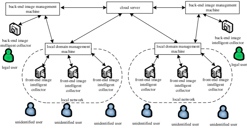
In these phases, the information transmission between the local domain management machine, the back-end image management machine, and the cloud server follows the SSL (secure socket layer) or TLS (transport later security) protocol. Its architecture diagram is shown in Figure1. The symbols and definitions used in this paper are shown in Table1.
cloud server
local domain management machine
front-end image intelligent
collector
front-end image intelligent
collector
front-end image intelligent
collector
local network back-end image
intelligent collector
unidentified user
local domain management machine
front-end image intelligent
collector
front-end image intelligent
collector
front-end image intelligent
collector
local network back-end image management
machine
back-end image intelligent collector back-end image management
machine
unidentified user
[image:5.595.100.510.384.598.2]unidentified user unidentified user unidentified user unidentified user legal user legal user
Table 1.Symbols and definitions.
Symbol Definition
LDMMj Thejthlocal domain management machine
BI MMj Thejthback-end image management machine
BI ICj Thejthback-end image intelligent collector
CS Cloud server
FI ICk Thekthfront-end image intelligent collector
U Legal user
U∗ Unidentified user
Ui Theithlegal user
Ti Theithtimestamp value generated by the front-end image intelligent collector
TSi Theithtimestamp value generated by the local domain management machine
ID(A) A’s identity information
PKk(A) Thekthpublic key generated byA
E(A)PK
k(B) EncryptAwith thek
thpublic key generated byB
SKk(A) Thekthprivate key generated byA
D(A)SKk(B) DecryptAwith thekthprivate key generated byB S(A)SK
k(B) SignAwith thek
thprivate key generated byB
V(A)PK
k(B) VerifyAwith thek
thpublic key generated byB
P(Ui) Image of legal userUi
A|⇒P(B) AcapturesBimage
(AlB)→C AtransfersBtoC
C←(AlB) CreceivesAtransmitted byB
DB(A) A’s database
A⇑DB(B) Abuild a database containingBinformation
A||B The parallel operation ofAandB
Φ(B) DemandB
(AlΦ(B))→C Atransmits demandBtoC
ACK Confirmation message
A. /B AcheckB
A⊗B AproducesB
A=?B WhetherAis equal toB
A⊕B AstoresB
Algorithm 1: The System Establishment Phase of User Image Intelligent Multi-Point Collaborative Authentication
1.BI ICj| ⇒P(Ui),(BI ICj lP(Ui))→BI MMj. 2.BI MMj←(BI ICj lP(Ui)),BI MMj
⇒ID(BI MMj),BI MMj|⇒ID(Ui).
3.BI MMj⇑DB(Ui||P(Ui)||ID(Ui)||BI MMj||ID(BI MMj)). 4.PK1(BI MMj),SK1(BI MMj),E(P(Ui)||ID(BI MMj))PK1(BI MMj),
(BI MMj lE(P(Ui)||ID(BI MMj))PK1(BI MMj))→LDMMj.
5.LDMMj←(BI MMjlE(P(Ui)||ID(BI MMj))PK1(BI MMj)),(LDMMjl
Φ(SK1(BI MMj)))→BI MMj.
6.BI MMj←(LDMMjlΦ(SK1(BI MMj))),(BI MMj lSK1(BI MMj))→LDMMj. 7.LDMMj←(BI MMjlSK1(BI MMj)),D(E(P(Ui)||ID(BI MMj))PK1(BI MMj))SK1(BI MMj).
8.LDMMj⇑DB(P(Ui)||BI MMj||ID(BI MMj)).
9.LDMMj. /((LDMMj⇑DB(P(Ui)||BI MMj||ID(BI MMj)))
?
=1), if it is not one, then go to (8), else(LDMMjlACK)→BI MMj.
10.BI MMj ←(LDMMj lACK),PK2(BI MMj),SK2(BI MMj). 11.E(P(Ui)||ID(Ui)||ID(BI MMj))PK2(BI MMj),(BI MMj l
E(P(Ui)||ID(Ui)||ID(BI MMj))PK2(BI MMj))→CS.
12.CS←(BI MMj l(E(P(Ui)||ID(Ui)||ID(BI MMj))PK2(BI MMj)),(CSl
Φ(SK2(BI MMj)))→BI MMj.
13.BI MMj ←(CSlΦ(SK2(BI MMj))),(BI MMjlSK2(BI MMj))→CS.
14.CS←(BI MMj lSK2(BI MMj)),D(P(Ui)||ID(Ui)||ID(BI MMj))PK2(BI MMj))SK2(BI MMj).
15.CS⇑DB(P(Ui)||ID(Ui)||ID(BI MMj)). 16.CS. /(DB(P(Ui)||ID(Ui)||ID(BI MMj))
?
=1), if it is not one, then go to (15), else (CSlACK)→BI MMj.
17.BI MMj ←(CSlACK),BI MMj. /(∃(Ui||P(Ui)||ID(Ui))
?
=1), if it is one, then go to (1), else go to (18).
18. End.
The specific process execution is described as follows:
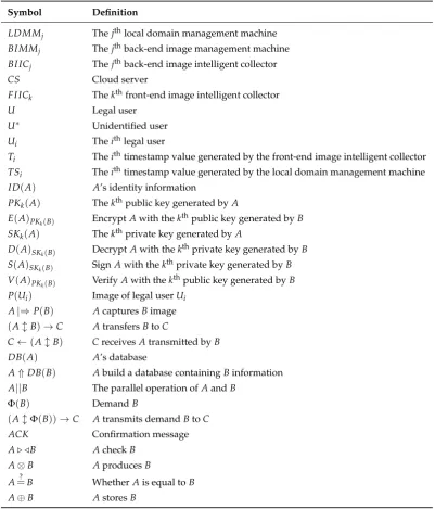
Step 1: The back-end image intelligent collectorBI ICj (j= 1, 2, 3, . . . , n) intelligently collects the imageP(Ui)of the legal userUi(i= 1, 2, 3, . . . , n) according to the requirements of the back-end manager. The legal user imageP(Ui)is transmitted to the corresponding back-end image management machineBI MMjvia the secret network.
Step 2: After receiving the legal user imageP(Ui)transmitted by the back-end image intelligent collector, the back-end image management machineBI MMjrequests the back-end manager to input the identity informationID(BI MMj)of the back-end image management machineBI MMjand the identity informationID(Ui)of this legal user.
curve encryption method. The encrypted file is sent to the local domain management machine via SSL or TLS.
Step 5: After receiving the encrypted file(P(Ui)||ID(BI MMj))PK1(BI MMj), the local domain
management machine applies it to the back-end image management machineBI MMjfor the private keySK1(BI MMj).
Step 6: After receiving the private key application of the local domain management machine, the back-end image management machineBI MMjsends the private keySK1(BI MMj)to the local domain management machine via SSL or TLS.
Step 7: After receiving the private keySK1(BI MMj)sent by the back-end image management machine BI MMj, the local domain management machine decrypts the received encrypted file (P(Ui)||ID(BI MMj))PK1(BI MMj).
Step 8: After decrypting the encrypted file(P(Ui)||ID(BI MMj))PK1(BI MMj), the local domain
management machine construct a corresponding local domain management image information databaseDB(P(Ui)|BI MMj||ID(BI MMj)). This database contains image informationP(Ui)of the legal user, the back-end image management machine nameBI MMj, and the identity information ID(BI MMj)of the back-end image management machineBI MMj.
Step 9: The local domain management machine determines whether the local domain management image information databaseDB(P(Ui)||BI MMj||ID(BI MMj))is constructed. If not, go the Step 8; otherwise, send confirmation message to the back-end image management machineBI MMj.
Step 10: After receiving the confirmation message sent by the local domain management machine, the back-end image management machineBI MMjgenerates a public keyPK2(BI MMj)and a corresponding private keySK2(BI MMj)according to the elliptic curve encryption method.
Step 11: The back-end image management machineBI MMjuses the public keyPK2(BI MMj)to encrypt imageP(Ui)of the legal user, the identity informationID(Ui)of the user image, and its own identity informationID(BI MMj)according to the elliptic curve encryption method, then sends its encrypted file(P(Ui)||ID(Ui)||ID(BI MMj))PK2(BI MMj)to the cloud server via SSL or TLS.
Step 12: After receiving the encrypted file(P(Ui)||ID(Ui)||ID(BI MMj))PK2(BI MMj), the cloud
server applies it to the back-end image management machineBI MMjfor the private keySK2(BI MMj). Step 13: After receiving the private key application of the cloud server, the back-end image management machineBI MMjsends the private keySK2(BI MMj)to the cloud server via SSL or TLS.
Step 14: After receiving the private key SK2(BI MMj) sent by the back-end image management machine BI MMj, the cloud server decrypts the received encrypted file (P(Ui)||ID(Ui)||ID(BI MMj))PK2(BI MMj).
Step 15: After decrypting the encrypted file (P(Ui)||ID(Ui)||ID(BI MMj))PK2(BI MMj),
the cloud server constructs a corresponding cloud server image information database DB(P(Ui)||ID(Ui)||ID(BI MMj)). This database contains the image informationP(Ui)of the legal user, the identity informationID(Ui)of the legal user, and the identity informationID(BI MMj)of the back-end image management machineBI MMj.
Step 16: The cloud server determines whether the cloud server image information database DB(P(Ui)||ID(Ui)||ID(BI MMj))is constructed. If not, go to Step 15; otherwise, send a confirmation message to the back-end image management machineBI MMj.
Step 17: After receiving the confirmation message sent by the cloud server, the back-end image management machineBI MMjdetermines whether the back-end manager needs the back-end image intelligent collector BI ICj to collect the legal user image, and if necessary, then go to the Step 1; otherwise, go to Step 18.
local domain management machine
back-end image intelligent collector legal user
back-end image management machine
cloud server S1: Collect legal user
image information
S3: Enter identity information
S4: Build the database
S5: Transfer the information and build
the database S2: Transfer legal user
image information
S6: Transfer the information and build
[image:9.595.121.486.135.368.2]the database
Figure 2.The system establishment phase’s brief process diagram.
3.2. The Authentication Phase of the Local Domain Management Machine and the Back-End Image Management Machine
Algorithm 2:The Authentication Phase of the Local Domain Management Machine and the Back-End Image Management Machine
1.FI ICk. /(∃(U∗||P(U∗))
?
=1), if it is one, then go to (3), else go to (2). 2.FI ICkwait 3 s, then go to (1).
3.FI ICk| ⇒ P(Un∗),FI ICk⊗Ti,(FI ICkl(P(U∗n)||Ti)→LDMMj.
4.LDMMj←(FI ICkl(P(U∗n)||Ti),LDMMj⊗TSi,LDMMj. /(((Ti−TSi)≥∆t)
?
=1), if it is one,LDMMjdeleteP(U∗n), then go to (2), else
LDMMj. /(∃P(Ui)∈(DB(P(Ui)||BI MMj||ID(BI MMj))),LDMMj. /(P(Ui)
?
=P(U∗n)), if ∃P(Ui)∈(DB(P(Ui)||BI MMj||ID(BI MMj)))andP(Ui) =P(U∗n), then go to (5), else delete P(U∗n), and go to (2).
5.message1 = (Apply for authentication),S(message1)SK(LDMM
j),
(LDMMjlS(message1)SK(LDMMj))→BI MMj.
6.BI MMj←(LDMMjlS(message1)SK(LDMMj)),V(S(message1)SK(LDMMj))PK(LDMMj) ?
=1, if it is one, then go to (7), else show “Apply for authentication failure”, and go to (3). 7.message=
(The authentication was successful, please transmit the image of the unidentified user), (BI MMjlE(message)PK1(BI MMj))→LDMMj.
8.LDMMj←(BI MMjlE(message)PK1(BI MMj)),D(E(message)PK1(BI MMj))SK1(BI MMj).
9.S(P(U∗n))SK(LDMMj),(LDMMjlS(P(U ∗
n))SK(LDMMj))→BI MMj.
10.BI MMj ←(LDMMj lS(P(Un∗))SK(LDMMj)),V(S(P(U ∗
n))SK(LDMMj))PK(LDMMj) ?
=1, if it is one, then go to (11), else show “The verification of the image of the unidentified user failed”, and go to (3).
11.BI MMj ←(FI ICklP(U∗n)).
12.BI MMj. /(∃P(Ui)∈DB(Ui||P(Ui)||ID(Ui)||BI MMj||ID(BI MMj)), BI MMj. /(P(Ui)
?
=P(U∗n)), if∃P(Ui)∈(DB(Ui||P(Ui)||ID(Ui)||BI MMj||ID(BI MMj))) andP(Ui) =P(U∗n), then show “The verification is success between the local domain management machine and the back-end image management machine”, and go to (13), else show “The verification failed between the local domain management machine and the back-end image management machine”, and go to (15).
13. message = (The verification was successful between the local domain management machine and the back-end image management machine),
(BI MMj lE(message)PK(BI MMj))→LDMMj.
14.BI MMj. /the transmission of the message is over. If it is over, then go to (15), else go to (13).
15. End.
The specific process execution is described as follows:
Step 1: The front-end image intelligent collectorFI ICkintelligently judges whether there is an unidentified user who needs image collection according to the surrounding scenes. If needed, then go to Step 3, otherwise, go to Step 2.
Step 2: The front-end image intelligent collectorFI ICkwaits for three seconds and then goes to Step 1.
Step 4: After receiving the image of the unidentified user and the current timestamp value (P(Un∗)||Ti)sent by the front-end image intelligent collectorFI ICk, the local domain management machine generates a timestamp valueTSi. Firstly, check if the session delayTi−TSiis within the allowable time interval∆t. If(Ti−TSi)≥∆t, the session times out, and delete the imageP(U∗n)of the unidentified user sent by the front-end image intelligent collectorFI ICk, then go to Step 2. Then, query the image informationP(Ui)of all legal users in the local domain management image information databaseDB(P(Ui)||BI MMj||ID(BI MMj)), and compare the legal user image informationP(Ui)in the databaseDB(P(Ui)||BI MMj||ID(BI MMj))with the imageP(U∗n)of the unidentified user sent by the front-end image intelligent collectorFI ICk. If the image informationP(Ui)of a certain legal user exists in the local domain management image information databaseDB(P(Ui)||BI MMj||ID(BI MMj)) and the imageP(Un∗)of the unidentified user sent by the front-end image intelligent collectorFI ICkis the same (i.e.,P(Un∗)=P(Ui)), go to Step 5; otherwise, delete the imageP(Un∗)of the unidentified user sent by the front-end image intelligent collectorFI ICk, then go to Step 2.
Step 5: According to the back-end image management machineBI MMj corresponding to the image informationP(Ui)of the legal user in the databaseDB(P(Ui)||BI MMj||ID(BI MMj)), the local domain management machine first uses the private key SK(LDMMj) and signs the “Apply for authentication” message, i.e., (“Apply for authentication”)SK(LDMMj). Then, it sends the signed message to the back-end image management machineBI MMj.
Step 6: After receiving the signature message (“Apply for authentication”))SK(LDMMj)sent by the
local domain management machine, the back-end image management machineBI MMjauthenticates the signature message by using the public key of the local domain management machine. If the authentication is successful, go to Step 7. Otherwise, display “Apply for authentication failure”, and go to Step 3.
Step 7: The back-end image management machine BI MMj encrypts the “The authentication is successful, please transmit the image of the unidentified user” message using the public key PK1(BI MMj), according to the elliptic curve encryption method, and then sends the encrypted message (“The authentication is successful, please transmit the image of the unidentified user”)PK1(BI MMj)to the local domain management machine via SSL or TLS.
Step 8: After receiving the encrypted message (“The authentication is successful, please transmit the image of the unidentified user”)PK1(BI MMj), the local domain management machine uses private
keySK1(BI MMj)to decrypt.
Step 9: According to the decrypted message, the local domain management machine first uses the private keySK(LDMMj)to sign the imageP(Un∗)message of the unidentified user collected by the front-end image intelligent collectorFI ICk, i.e.,(P(Un∗))SK(LDMMj). Then, the signed message is sent
to the back-end image management machineBI MMj.
Step 10: After receiving the signature message (P(Un∗))SK(LDMMj) sent by the local domain
management machine, the back-end image management machineBI MMjauthenticates the signature message by using the public key of the local domain management machine. If the authentication is successful, go to Step 11. Otherwise, display “The verification of the image of the unidentified user failed”, and go to Step 3.
Step 11: The back-end image management machineBI MMj receives the image P(U∗n) of the unidentified user sent by the front-end image intelligent collectorFI ICk.
between the local domain management machine and the back-end image management machine”. Otherwise, the back-end image management machine BI MMj displays “The verification failed between the local domain management machine and the back-end image management machine” and goes to Step 15.
Step 13: The back-end image management machineBI MMjencrypts the image authentication result message “The verification is successful between the local domain management machine and the back-end image management machine” and then sends its encrypted message to the local domain management machine via SSL or TLS.
Step 14: The back-end image management machine BI MMj determines whether the image authentication result message is sent. If sent, go to Step 15; otherwise, go to Step 13.
Step 15: End.
unidentified user
front-end image intelligent
collector
back-end image management machine
local domain management machine S1: Collect unidentified
user image information
S3: Compare unidentified user image information with legal user image information in the database
S4: Transfer unidentified user image information S2: Transfer unidentified
user image information
S5: Compare unidentified user image information with legal user image information in the database
[image:12.595.127.489.283.529.2]S6: Transfer the results of authentication
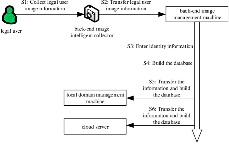
Figure 3.The authentication phase of the local domain management machine and the back-end image management machine brief process diagram.
3.3. The Authentication Phase of the Local Domain Management Machine and Cloud Server
Algorithm 3:The Authentication Phase of the Local Domain Management Machine and Cloud Server
1.LDMMj←(BI MMjlE(message)PK(BI MMj)),D(E(message)PK(BI MMj))SK(BI MMj).
2.LDMMj. /The verification of the message is successful, if the verification is successful, then go to (3), else go to (13).
3.message1 = (Apply for authentication),S(message1)SK(LDMMj), (LDMMj lS(message1)SK(LDMMj))→CS.
4.CS←(LDMMjlS(message1)SK(LDMMj)),V(S(message1)SK(LDMMj))PK(LDMMj) ?
=1, if it is one, then go to (5), else show “Apply for authentication failure” and go to (13).
5.message2 = (The authentication is successful, please transmit the image of the unidentified user),(CSlE(message2)PK
1(BI MMj))→LDMMj.
6.LDMMj←(CSlE(message2)PK1(BI MMj)),D(E(message2)PK1(BI MMj))SK1(BI MMj).
7.S(P(U∗n))SK(LDMMj),(LDMMjlS(P(U ∗
n))SK(LDMMj))→CS.
8.CS←(LDMMjlS(P(U∗n))SK(LDMMj)),V(S(P(U ∗
n))SK(LDMMj))PK(LDMMj) ?
=1. If it is one, then go to (9), else show “The authentication of the image of the unidentified user failed”, and go to (13).
9.CS←(FI ICklP(U∗n)).
10.CS. /(∃P(Ui)∈ DB(P(Ui)||ID(Ui)||ID(BI MMj)),CS. /(P(Ui)
?
=P(U∗n)), if
∃P(Ui)∈(DB(P(Ui)||ID(Ui)||ID(BI MMj)))andP(Ui) =P(U∗n), then the cloud server shows “The verification is successful between the local domain management machine and the cloud server”, and go to (11), else the cloud server shows “The verification failed between the local domain management machine and the cloud server”, and go to (13).
11.message3 = (The verification is successful between the local domain management machine and the cloud server),(CSlE(message3)PK(BI MMj))→LDMMj,
(CSlE(message3)PK(BI MMj))→BI MMj.
12.CS. /the transmission of the message is over. If it is over, then go to (13), else go to (11). 13. End.
The specific process execution is described as follows:
Step 1: The local domain management machine receives the image authentication result message sent by the back-end image management machineBI MMjand decrypts the message.
Step 2: The local domain management machine determines the decrypted image authentication result message. If the authentication with the local domain management machine is successful, the process goes to Step 3. Otherwise, the process goes to Step 13.
Step 3: The local domain management machine first signs the “Apply for authentication” message using the private keySK(LDMMj), i.e. (“Apply for authentication”))SK(LDMMj), then sends the signed
message (“Apply for authentication”))SK(LDMMj)to the cloud server.
Step 4: After receiving the signature message (“Apply for authentication”))SK(LDMMj)sent by the
local domain management machine, the cloud server authenticates the signature message (“Apply for authentication”))SK(LDMMj)by using the public key of the local domain management machine. If
the authentication is successful, go to Step 5. Otherwise, display “Apply for authentication failure”, and go to Step 13.
Step 6: After receiving the encrypted message (“The authentication is successful, please transmit the image of the unidentified user”)PK1(BI MMj), the local domain management machine uses the private keySK1(BI MMj)to decrypt the message.
Step 7: According to the decrypted message, the local domain management machine first uses the private key SK(LDMMj) to sign the collected image P(Un∗) of the unidentified user, i.e.,P(Un∗))SK(LDMMj), then sends the signature message(U
∗
n))SK(LDMMj)to the cloud server.
Step 8: After receiving the signature message P(Un∗))SK(LDMMj) sent by the local domain
management machine, the cloud server authenticates the signature messageP(Un∗))SK(LDMMj) by
using the public key of the local domain management machine. If the authentication is successful, go the Step 9. Otherwise, display “The authentication of the image of the unidentified user failed” and go to Step 13.
Step 9: The cloud server receives the imageP(Un∗)of the unidentified user sent by the front-end image intelligent collectorFI ICk.
Step 10: The cloud server first queries the image information P(Ui) of all legal users in its databaseDB(P(Ui)||ID(Ui)||ID(BI MMj))and compares the legal user image informationP(Ui)in the databaseDB(P(Ui)||ID(Ui)||ID(BI MMj))with the imageP(Un∗)of the unidentified user sent by the front-end image intelligent collectorFI ICk. If the image informationP(Ui)of a certain legal user exists in the cloud server databaseDB(P(Ui)||ID(Ui)||ID(BI MMj))and the imageP(Un∗)of the unidentified user sent by the front-end image intelligent collectorFI ICkare the same (i.e.,P(Un∗)= P(Ui)), the cloud server displays “The verification is successful between the local domain management machine and the cloud server”. Otherwise, the cloud server displays “The verification failed between the local domain management machine and the cloud server” and goes to Step 13.
Step 11: The cloud server encrypts the image authentication result message “The verification is successful between the local domain management machine and the cloud server” and then sends the encrypted message to the local domain management machine and the corresponding back-end image management machineBI MMjvia SSL or TLS.
Step 12: The cloud server determines whether the image authentication result message is sent. If sent, go to Step 13; otherwise, go to Step 11.
Step 13: End.
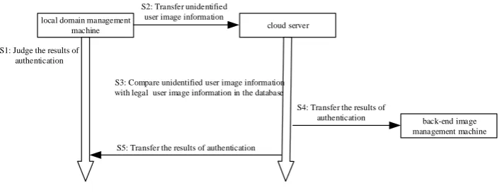
local domain management
machine cloud server
S1: Judge the results of authentication
S2: Transfer unidentified user image information
S3: Compare unidentified user image information with legal user image information in the database
back-end image management machine S4: Transfer the results of
authentication
[image:14.595.134.489.507.645.2]S5: Transfer the results of authentication
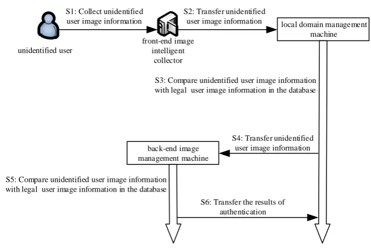
Figure 4.The authentication phase of the local domain management machine and cloud server brief process diagram.
3.4. The Authentication Phase of the Back-End Image Management Machine and Cloud Server
server image information database. Next, compare the image information and the identity information with the image of the unidentified user, which has been authenticated by the signature and the identity information of the unidentified user. Finally, complete mutual authentication between the back-end image management machine and the cloud server. The brief process diagram is shown in Figure5. The algorithm is shown in Algorithm4.
Algorithm 4:The Authentication Phase of the Back-End Image Management Machine and Cloud Server
1.BI MMj←(CSlE(message3)PK(BI MMj)),D(E(message3)PK(BI MMj))SK(BI MMj).
2.BI MMj. /The verification of the message is success . If the verification is success, then go to (3), else go to (14).
3.message1 = (Apply for authentication),S(message1)SK(BI MM
j),
(BI MMj lS(message1)SK(BI MMj))→CS.
4.CS←(BI MMjlS(message1)SK(BI MMj)),V(S(message1)SK(BI MMj))PK(BI MMj) ?
=1, if it is one, then go to (5), else show “Apply for authentication failure”, and go to (13).
5.message2 = (The authentication is successful, please transmit the image of the unidentified user),(CSlE(message2)PK1(BI MM
j))→BI MMj.
6.BI MMj←(CSlE(message2)PK1(BI MMj)),D(E(message2)PK1(BI MMj))SK1(BI MMj).
7.S P(U∗n)||ID(U∗n)||ID(BI MMj)
SK(BI MMj),
(BI MMjlS P(U∗n)||ID(U∗n)||ID(BI MMj)
SK(BI MMj))→CS.
8.CS←(BI MMjlS P(U∗n)||ID(U∗n)||ID(BI MMj)SK(BI MM
j)),
V(S P(U∗n)||ID(U∗n)||ID(BI MMj)SK(BI MM
j))PK(BI MMj) ?
=1. If it is one, then go to (9), else
show “The authentication of the image of the unidentified user failed between the cloud server and the back-end image management machine”, and go to (13).
9.CS⊕(P(U∗n)||ID(U∗n)||ID(BI MMj)).
10.CS. /(∃P(Ui)∈ DB(P(Ui)||ID(Ui)||ID(BI MMj)), CS. /(P(Ui)
?
=P(U∗n)∧ID(Ui)
?
=ID(U∗n)), if∃P(Ui)∈(DB(P(Ui)||ID(Ui)||ID(BI MMj))) andP(Ui) =P(U∗n)∧ID(Ui) =ID(U∗n), then the cloud server shows “The verification is successful between the back-end image management machine and the cloud server”, and go to (11), else the cloud server shows “The verification failed between the back-end image management machine and the cloud server”, and go to (13).
11.message3 = (The verification is successful between the back-end image management machine and the cloud server),
(CSlE(message3)PK(BI MMj))→LDMMj,(CSlE(message3)PK(BI MMj))→BI MMj.
12.CS. /the transmission of the message is over. If it is over, then go to (13), else go to (11). 13. End.
The specific process execution is described as follows:
Step 1: The back-end image management machineBI MMjreceives the image authentication result message sent by the cloud server and decrypts the message.
Step 2: The back-end image management machine BI MMj determines the decrypted image authentication result message, and if it is “The verification is successful between the local domain management machine and the cloud server”, go to Step 3; otherwise, go to Step 14.
Step 3: The back-end image management machine BI MMj first signs the “Apply for authentication” message using the private key SK(BI MMj), i.e., (“Apply for authentication”)SK(BI MMj), then sends the signed message (“Apply for authentication”)SK(BI MMj)to
Step 4: After receiving the signature message (“Apply for authentication”)SK(BI MMj)sent by the
back-end image management machineBI MMj, the cloud server authenticates the signature message (“Apply for authentication”)SK(BI MMj)by using the public key of the back-end image management
machineBI MMj. If the authentication is successful, go to Step 5. Otherwise, display “Apply for authentication failure”, and go to Step 13.
Step 5: The cloud server encrypts the “The authentication is successful, please transmit the image of the unidentified user” message according to the elliptic curve encryption method using the public keyPK1(BI MMj)and then sends the encrypted message (“The authentication is successful, please transmit the image of the unidentified user”)PK1(BI MMj)to the back-end image management machine
BI MMjvia SSL or TLS.
Step 6: After receiving the encrypted message, the back-end image management machineBI MMj decrypts the message by the private keySK1(BI MMj).
Step 7: According to the decrypted message, the back-end image management machine BI MMj first uses the private key SK(BI MMj) to sign the image P(Un∗) of the unidentified user sent by the local domain management machine. Then, sign its corresponding user identity information, which is initially compared successfully by the local domain management machine and the back-end image management machineBI MMj. Finally, sign its own identity information ID(BI MMj), i.e., ((P(Un∗)||(ID(Un∗)||ID(BI MMj))SK(BI MMj), then send the signature message
((P(Un∗)||(ID(U∗n)||ID(BI MMj))SK(BI MMj)to the cloud server.
Step 8: After receiving the signature message((P(Un∗)||(ID(Un∗)||ID(BI MMj))SK(BI MMj) sent
by the back-end image management machineBI MMj, the cloud server authenticates the signature message by using the public key of the back-end image management machineBI MMj. If the signature authentication is successful, go to Step 9, otherwise, display “The authentication of the image of the unidentified user failed between the cloud server and the back-end image management machine”, and go to Step 13.
Step 9: The cloud server stores the image P(Un∗) of the unidentified user, which has been authenticated by the signature, its corresponding user identity informationID(U∗n), and identity informationID(BI MMj)of the back-end image management machineBI MMj.
Step 10: The cloud server first queries the image information P(Ui) of all legal users, the identity information ID(Ui) of the legal user, and the identity information ID(BI MMj) of the back-end image management machine BI MMj in the cloud server image information databaseDB(P(Ui)||ID(Ui)||ID(BI MMj). Then, it respectively compares the image P(Un∗)of the unidentified user, which has been authenticated by the signature and the identity information ID(Un∗) of the unidentified user image with the image information P(Ui) of all legal users and the identity information ID(Ui) of the legal user in the cloud server image information database DB(P(Ui)||ID(Ui)||ID(BI MMj). If there is image information P(Ui) of a legal user and identity information ID(Ui) of a legal user in the cloud server image information database DB(P(Ui)||ID(Ui)||ID(BI MMj)), this image informationP(Ui)and identity informationID(Ui)are respectively the same as the image P(Un∗)of the unidentified user, which has been authenticated by the signature and the identity informationID(Un∗)of the unidentified user image, i.e., (P(Un∗)= P(Ui),ID(Un∗)=ID(Ui)), and the cloud server displays “The verification is successful between the back-end image management machine and the cloud server”. Otherwise, the cloud server displays “The verification failed between the back-end image management machine and the cloud server”,
and it goes to Step 13.
Step 11: The cloud server encrypts the image authentication result message “The verification is successful between the back-end image management machine and the cloud server” and then sends the encrypted message to the local domain management machine and the corresponding back-end image management machineBI MMjvia SSL or TLS.
Step 13: End.
back-end image
management machine cloud server
S1: Judge the results of authentication
S2: Transfer unidentified user image and identity information
S3: Compare unidentified user image information and identity information with legal user image information and identity information in the database
local domain management machine S4: Transfer the results of
authentication
[image:17.595.126.497.127.263.2]S5: Transfer the results of authentication
Figure 5.The authentication phase of the back-end image management machine and cloud server brief process diagram.
4. Security and Cost Analysis
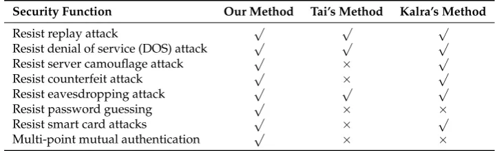
In this section, firstly, we analyze the security of the multi-point collaborative authentication method based on user image intelligent collection and compare our method with Tai’s method [5] and Kalra’s method [15]. Secondly, we analyze the cost of our method, and the specific description is as follows. The analysis of safety functions is shown in Table2.
4.1. Security Analysis
Table 2.Analysis of safety functions.
Security Function Our Method Tai’s Method Kalra’s Method
Resist replay attack √ √ √
Resist denial of service (DOS) attack √ √ √
Resist server camouflage attack √ × √
Resist counterfeit attack √ × √
Resist eavesdropping attack √ √ √
Resist password guessing √ × ×
Resist smart card attacks √ × √
Multi-point mutual authentication √ × ×
4.1.1. Resist Replay Attack and Denial of Service Attack
[image:17.595.115.475.446.556.2]4.1.2. Resist Server Camouflage Attack and Counterfeit Attack
In this method, a malicious attacker cannot masquerade as the local domain management machine to send the imageP(U∗n)of the unidentified user to the back-end image management machine for authentication and cannot send fakeP(Un∗)information to defraud authentication. Before sending the P(Un∗)to the back-end image management machine, the local domain management machine first signs the “Apply for authentication” with the private key SK(LDMMj)and sends it to the back-end image management machine. The back-end image management machine uses the public keyPK(LDMMj)to decrypt the information. Then, it determines whether the application is sent by the local domain management machine. It can prevent the attacker from disguising the local domain management machine to destroy the authentication and resist the server camouflage attack. After the message is successfully authenticated, the back-end image management machine uses the ellipse encryption algorithm to encrypt the “The authentication is successful, please transmit the image of unidentified user” message and sends it to the local domain management machine. Finally, the local domain management machine uses the private keySK(LDMMj)to sign theP(Un∗)and sends it to the back-end image management machine. The back-end image management machine determines whether theP(Un∗)is sent by the local domain management machine by decrypting the information with the public keyPK(LDMMj). It can prevent the attacker from impersonatingP(Un∗)information to destroy the authentication and resist the counterfeit attack. Similarly, the authentication phase of the local domain management machine and the cloud server and the authentication phase of the back-end image management machine and the cloud server need to be authenticated in this form. It can also resist server camouflage attack and counterfeit attack. In Tai’s method, the sensor node is exposed in public. If a malicious attacker destroys any node, then he/she can pretend that the user is logged into the normal legal sensor node and launch a counterfeit attack on other sensor nodes.
4.1.3. Resist Eavesdropping Attack and Password Guessing
This method does not use passwords for identity authentication. The only identity information is legal user image informationP(Ui). During the system establishment phase, the malicious attacker cannot steal the legal user image informationP(Ui)sent by the back-end image management machine BI MMjto the local domain management machine and the cloud server from the common channel. Because the legal user image informationP(Ui)is encrypted by the ellipse encryption algorithm in the common channel, the attacker cannot calculate theP(Ui) information in polynomial time. In Tai’s method, the user’s password is stored in the smart card. Once the smart card is stolen by an authorized malicious attacker, he/she can guess and calculate the actual password of the smart card owner. In Kalra’s method, a malicious attacker first guesses the password and calculates it to verify that the password is the correct one. If not, repeat the guess. The attacker can guess the correct password in a brute force way.
4.1.4. Resist Smart Card Attacks
In this method, image intelligent collection technology is used for identity authentication. Compared with the traditional smart card authentication method, the image intelligent collection method is less expensive and has better security and portability. There is no risk of lost, stolen, or duplicated smart cards, and there is no need to defend against attackers’ attacks on smart card data. In Tai’s method, user information is stored in a smart card. Once a smart card is stolen or lost, a malicious attacker can extract all the private information stored in the smart card.
4.1.5. Multi-Point Collaborative Authentication
authentication phase of the local domain management machine and the back-end image management machine, the local domain management machine needs to compare the unidentified user imageP(Un∗) sent by the front-end image collector with the legal user imageP(Ui)in the database constructed in the system establishment phase. If the same (i.e.,P(Un∗)=P(Ui)), the local domain management machine encrypts the unidentified user imageP(Un∗)and transmits it to the back-end image management machine. Finally, compare it with the legal user image P(Ui) in the database built internally to complete the phase authentication. The principle of the authentication phase of the local management machine and the cloud server and the principle of the authentication phase of the back-end image management machine and the cloud server are similar. If a privileged attacker steals or modifies the database information in some way and destroys the authentication at a certain phase, it cannot pass the collaborative identity authentication. In Tai’s method, the sensor nodes, gateway nodes, and users provided by the company cannot authenticate each other. In Kalra’s method, the embedded devices and cloud servers provided by them cannot mutually confirm the legitimacy of each other. Therefore, their methods are more vulnerable to spoofing attacks.
4.2. Cost Analysis
The method uses the symmetric encryption algorithm and the asymmetric encryption algorithm. The characteristics of the symmetric encryption algorithm and the asymmetric encryption algorithm show that the symmetric encryption algorithm uses the same key for encryption and decryption, and the operation is fast, but easy to crack. The asymmetric encryption algorithm uses public key encryption and private key decryption, which is slow, but not easy to crack. The calculation of the operation of an asymmetric encryption algorithm (A) is equivalent to a point operation and is also equal to 1000 symmetric encryption algorithm operations (S). Therefore, assuming that the calculation cost of the asymmetric encryption algorithm operation (A) is one, the calculation cost of the symmetric encryption algorithm operation (S) is 0.001. The results of the cost analysis at different phases are shown in Table3.
Table 3.Method costs.S, symmetric;A, asymmetric.
NLegal Identity Users in the System and the Operating Cost of CollectingMUnidentified Users
System establishment phase 4S×N= 0.004N
The authentication phase of local domain management machine and back-end image management machine
(6S+ 1A)×M= 1.006M
The authentication phase of local domain
management machine and cloud server (6S+ 2A)×M= 2.006M
The authentication phase of the back-end image
management machine and cloud server. (6S+ 2A)×M= 2.006M
Complete method (18S+ 5A)×M+ 4S×N= 5.018M+ 0.004N
5. Conclusions and Future Work
authentication phase of the back-end image management machine and cloud server. To demonstrate the validity of the method for identity authentication, a series of security analyses was conducted. Compared with the traditional single identity authentication method, our method used three-party collaborative authentication to avoid the problem of sensor information stealing easily caused by a single authentication method, which makes the user’s identity authentication more secure and effective. The analysis results showed that the method was able to resist multiple types of attacks to meet the security requirements, attacks such as replay attacks, denial of service attacks, and server camouflage attacks. In addition, the results also indicated that the method was suitable for identity authentication in the IoT environment.
This paper did not cover the field of image acquisition and authentication, but only compared the user’s image information. Therefore, it is not yet possible to estimate the impact of image acquisition and authentication on the cost, efficiency, and security of the method. In addition, image acquisition and authentication are also affected by many factors, such as ambient lighting, which result in a reduction in the recognition rate and performance. Therefore, the future work is to optimize the algorithms for image acquisition and authentication and consider adding biometrics such as fingerprint recognition to protect the identity authentication and improve the accuracy of identity authentication.
Author Contributions: Conceptualization, Y.L. and Y.T.; formal analysis, Y.T.; funding acquisition, Y.L.; methodology, Y.L. and Y.T.; resources, Y.L.; supervision, Y.L. and J.L.; visualization, Y.T.; writing—original draft, Y.T. and J.L.; writing—review and editing, Y.T. and J.L.
Funding: This research was funded by the Zhejiang Provincial Natural Science Foundation of China Grant Number Y20F020088.
Conflicts of Interest:The authors declare no conflict of interest.
References
1. Tai, W.-L.; Chang, Y.-F.; Li, W.-H. An IoT notion–based authentication and key agreement scheme ensuring user anonymity for heterogeneous ad hoc wireless sensor networks.J. Inf. Secur. Appl.2017,34, 133–141. [CrossRef]
2. Challa, S.; Wazid, M.; Das, A.K.; Kumar, N.; Reddy, A.G.; Yoon, E.J.; Yoo, K.Y. Secure Signature-Based Authenticated Key Establishment Scheme for Future IoT Applications. IEEE Access2017,5, 3028–3043. [CrossRef]
3. Hu, P.; Ning, H.; Qiu, T.; Song, H.; Wang, Y.; Yao, X. Security and Privacy Preservation Scheme of Face Identification and Resolution Framework Using Fog Computing in Internet of Things.IEEE Internet Things J.
2017,4, 1143–1155. [CrossRef]
4. Dhillon, P.K.; Kalra, S. Secure and efficient ECC based SIP authentication scheme for VoIP communications in internet of things.Multimed. Tools Appl.2019,5, 1–24. [CrossRef]
5. Zhang, M.; Ma, Z.; Zhang, Y.; Wang, Y. An identity authentication scheme based on cloud computing
environment.Multimediea Tools Appl.2018,77, 4283–4294. [CrossRef]
6. Al-Turjman, F.; Ever, Y.K.; Ever, E.; Nguyen, H.X.; David, D.B. Seamless Key Agreement Framework for
Mobile-Sink in IoT Based Cloud-Centric Secured Public Safety Sensor Networks. IEEE Access2017, 5, 24617–24631. [CrossRef]
7. Kalra, S.; Sood, S.K. Secure authentication scheme for IoT and cloud servers.Pervasive Mob. Comput.2015,24, 210–223. [CrossRef]
8. Mo, J.; Hu, Z.; Lin, Y. Remote user authentication and key agreement for mobile client–server environments on elliptic curve cryptography.J. Supercomput.2018,74, 5927–5943. [CrossRef]
9. Jiang, Q.; Zeadally, S.; Ma, J.; He, D. Lightweight Three-Factor Authentication and Key Agreement Protocol for Internet-Integrated Wireless Sensor Networks.IEEE Access2017,5, 3376–3392. [CrossRef]
11. Xu, L.; Wu, F. A Lightweight Authentication Scheme for Multi-gateway Wireless Sensor Networks Under IoT Conception.Arab. J. Sci. Eng.2019,44, 3977–3993. [CrossRef]
12. Gong, B.; Wang, Y.; Liu, X.; Qi, F.; Sun, Z. A Trusted Attestation Mechanism for the Sensing Nodes of Internet of Things Based on Dynamic Trusted Measurement.China Commun.2018,15, 100–121. [CrossRef]
13. Zhang, Q.; Xu, D. Security authentication technology based on dynamic Bayesian network in Internet of Things.J. Ambient Intell. Humaniz. Comput.2018, 1–8. [CrossRef]
14. Xie, R.; He, C.; Xu, C.; Gao, C. Lattice-based dynamic group signature for anonymous authentication in IoT.
Ann. Telecommun.2019,74, 531–542. [CrossRef]
15. Shen, H.; Shen, J.; Khan, M.K.; Lee, J.H. Efficient RFID Authentication Using Elliptic Curve Cryptography for the Internet of Things.Wirel. Pers. Commun.2017,96, 5253–5266. [CrossRef]
16. Fan, K.; Ge, N.; Gong, Y.; Li, H.; Su, R.; Yang, Y. An ultra-lightweight RFID authentication scheme for mobile commerce.Peer Peer Netw. Appl.2017,10, 368–376. [CrossRef]
17. Aghili, S.F.; Ashouri-Talouki, M.; Mala, H. DoS, impersonation and de-synchronization attacks against an ultra-lightweight RFID mutual authentication protocol for IoT. J. Supercomput. 2018, 74, 509–525. [CrossRef]
c