UNIVERSITI TEKNIKAL MALAYSIA MELAKA
SYSTEMATIC DEVELOPMENT OF INJECTION MOLD: A
CONVOCATION SOUVENIR
This report is submitted in accordance with the requirement of the Universiti Teknikal Malaysia Melaka (UTeM) for the Bachelor Degree of Manufacturing Engineering
Technology (Process and Technology) with Honours
by
ASMA NOR HIDAYAH BINTI ABDULLAH B071310249
910521-06-5858
DECLARATION
I hereby, declared this report entitled “Systematic Development of Injection Mold: A Convocation Souvenir” is the results of my own research except as cited in references.
Signature : ……….
Author‟s Name : ASMA NOR HIDAYAH BINTI ABDULLAH
APPROVAL
This report is submitted to the Faculty of Engineering Technology of UTeM as a partial fulfillment of the requirements for the degree of Bachelor of Manufacturing Engineering Technology (Process and Technology) with Honours. The member of the supervisory is as follow:
………
i
ABSTRACT
ii
ABSTRAK
Proses acuan suntikan adalah salah satu dari proses penting dalam penghasilan produk plastik dimana proses ini mempunyai kelebihan sebagai satu kaedah pembuatan alternatif, termasuklah kerugian minimum dari lebihan dan minimum keperluan kemasan. Dalam penghasilan sesuatu produk plastik yang baru, mesin acuan suntikan memerlukan acuan yang baru. Pada masa sekarang, proses dalam menghasilkan acuan suntikan memerlukan ilmu pengetahuan yang tinggi, kos yang tinggi, jangka masa yang panjang dan memerlukan pembuat acuan yang berpengalaman. Kaedah cuba gagal masih dianggap sebagai kaedah mencari penyelesaian dalam pembuatan acuan. Lazimnya acuan akan di uji pada mesin suntikan dan pada masa ini segala permasalahan atau kecacatatan pada produk dapat dikenalpasti. Namun penyelesaian kepada masalah tersebut memerlukan kos dan masa yang panjang untuk melakukan modifikasi pada acuan atau terus mencari parameter suntikan yang terbaik. Dalam projek ini suatu kaedah yang lebih sistematik diperkenalkan dengan mengunakan beberapa aplikasi CAD/CAE dan CAM untuk menghasilkan acuan. Perisian CAE seperti Autodesk Moldflow telah digunakan untuk mencari parameter suntikan dan semasa rekabentuk acuan. Beberapa kecacatan produk telah dikenalpasti dan diatasi
iii
DEDICATIONS
Firstly, dissertation is dedicated to my beloved parent, Mr. Abdullah bin Abd Majid and Mrs. Faezah binti Habas, that encouraged and put their trust on me to complete this project. Not forgetting to my sibling, their supports are the reason why and
who I am right now.
My deepest gratitude also were given to Mr. Mohd Faizal bin Halim as my supervisor whose passion for teaching set a new knowledge that can be apply, not only
in this project, also can be implement in daily routine.
Other than that, thanks also give to technicians Faculty of Engineering Technology (FTK), Mr. Azimin, Mr. Hisham, Mr. Basri, Mr. Azizul Ikhwan, Mr. Khairul
Affendi and Mr. Fauzi those who always gave good co-operation and time in order to complete this research.
iv
ACKNOWLEDGMENTS
Primarily I would like thank to Allah S.W.T for being able to complete this project with success. Then this appreciation to Mr. Mohd Faizal Bin Halim, whose valuable guidance that helped me patches this project. Because of his guidance on suggestion and improvement bring major contributor toward completing of the project.
Thank also goes to all technicians that share their experienced and knowledge during completing this project. I would like to thank to the lecturer in Universiti Teknikal
Malaysia Malacca who always gave their support and guidance to me in order to make improvement from time to time.
v
TABLE OF CONTENT
Abstrak i
Abstract ii
Dedication iii
Acknowledgement iv
Table of Content v
List of Tables ix
List of Figures x
List Abbreviations, Symbol and Nomenclature xiii
CHAPTER 1: INTRODUCTION 1
1.0 Introduction 1
1.1 Problem statement 4
1.2 Objectives 5
1.3 Scopes 5
CHAPTER 2: LITERATURE REVIEW 6
2.0 Introduction 6
2.1 Traditional Injection Molding Processs 6
2.2 Systematic Molding 7
2.3 Injection Molding Machine 9
2.3.1 Process of injection molding 10
2.3.2 Injection Molding Parameter 11
2.4 Molds 12
2.4.1 Parting Line 14
vi
2.4.2.1 Sprue 14
2.4.2.2 Runner 15
2.4.2.3 Gates 16
2.4.3 Insert Mold 17
2.5 Mold Making Technique 19
2.5.1 Rapid Tooling 20
2.5.2 High Speed Machining 20
2.5.3 Electrical Discharge Machining (EDM) 21
2.6 Mold Flow Simulation 22
2.7 Raw Material 23
2.8 Product Design 24
2.8.1 Solidwork 25
2.8.2 Shrinkage 26
2.8.3 Wall Thickness 28
2.8.4 Draft Angle 29
2.8.5 Corner Design (Fillet, Radius and Chamfer) 30
2.9 Defects in Injection Molding 33
2.10 Summary 36
CHAPTER 3: METHODOLOGY 37
3.0 Overview 37
3.1 Flowchart 38
3.2 3D designs 39
3.2.1 Design 1 39
3.2.2 Design 2 40
3.2.3 Design 3 40
3.2.4 Design 4 41
3.2.5 Design 5 41
3.3 Designs for Plastic Part 42
3.3.1 Fillet 42
vii
3.3.3 Draft 43
3.4 Measuring the Insert 45
3.5 Considering the Ejector Pin Location 46
3.6 Mold Flow Simulation 47
3.6. 1 Material Selection 47
3.6. 2 Part Filling Optimization 48
3.6.2.1 Determine the Number of Gate 48
3.6.2.2 Position the Gate for Balanced Filling 49
3.6.3 Molding Condition 50
3.6.4 Runner System 50
3.7 Core and Cavity Design 51
3.7.1 Parting Line 51
3.7.2 Shut-Off Surface 52
3.7.3 Parting Surface 53
3.7.4 Tooling Split 53
3.7.5 Cavity Design 54
3.7.6 Core Design 56
3.8 Mold Fabrication 57
3.8.1 Squaring Process 57
3.8.2 Machining Program 58
3.8.3 Machining Process 60
3.9 Mold Assembly 61
3.10 Injection Molding Process 63
CHAPTER 4: RESULT AND ANALYSIS 65
4.0 Overview 65
viii 4.1.5 Discussion on Different Gate Location by Moldflow Advisor 74 4.2 Minimum Defect Analysis on Different Gate Location 76
4.2.1 Result on Air Trap for Gate Location 1 76 4.2.2 Result on Air Trap for Gate Location 2 77
4.2.3 Discussion on Air Trap Result 79
4.2.4 Result on Weld Line for Gate Location 1 79 4.2.5 Result on Weld Line for Gate Location 2 81
4.2.6 Discussion on weld line Result 82
4.3 Mold Fabrication Using 3-Axis CNC Machine 83
4.3.1 Machining Complexity 83
4.3.2 Machining Error 85
4.4 Injection Molding Process 85
4.4.1 Different Result between Simulation and Experimental 86
4.4.2 Part Was Unable To Eject 88
CHAPTER 5: CONCLUSION AND RECOMMENDATION 90
5.1 Conclusion 90
5.2 Recommendation for Future Work 91
APPENDICES
Appendix A - Gantt Chart
Appendix B - Ejector Pin Tax Invoice
Appendix C - Result On CMM Measuring
Appendix D - Detail Drawing
ix
LIST OF TABLES
2.1 Feed System Types and Properties 17
2.2 Melt Temperature, Residence Time, and Circumferential Speed
Recommend For Some Engineering Thermoplastic 24 2.3 Type of Defect and Possible Causes during Injection Molding 33
3.1 Material Quality Indicator by Moldflow Advisor for PP 48
3.2 Cutting Tool Used for Machining 60
4.1 Recommended Process for PP material 67
4.2 Result of Molding Window 67
4.3 Result on Fill Time of Condition used using Moldflow Analysis 69 4.4 Result on Melt Temperature 220 (C) for Gate Location 1 70 4.5 Result on Melt Temperature 200 (C) for Gate Location 1 71 4.6 Result on Melt Temperature 220 (C) for Gate Location 2 72 4.7 Result on Melt Temperature 200 (C) for Gate Location 2 73
4.8 Result on Air Trap for Gate Location 1 76
4.9 Result on Air Trap for Gate Location 2 78
4.10 Result on Weld Line for Gate Location 1 80
4.11 Result on Weld Line for Gate Location 2 81
x
LIST OF FIGURES
1.1 Conventional Method of Injection Molding Process 2 1.2 Keris Panjang Is Symbol of the University Authority 3
2.1 Injection Molding Approach with Computer Aided Engineering Tool 9
2.2 Injection Molding Machine 10
2.3 Schematic View of Injection Molding Machine 11 2.4 Process Steps in the Injection Molding Of A Component 12 2.5 Cross Sectional View Of A Common Mold Assembly 13
2.6 Series Layout of Runner System 16
2.7 Cavity Plate for Cavity Insert 18
2.8 Core Plate for Core Insert 19
2.9 Rapid Prototype Machine 20
2.10 EDM Wire Cut Machine 21
2.11 Relationship Between Shrinkage And Characteristic Parameter 27
2.12 Possible Wall Thickness Changes 28
2.13 Exponential Increase Of Cooling Time With Recpect To Wall
Thickness For Three Common Plastic Materials 29 2.14 Draft On The Inside And Outside Surfaces Of A Part Should Be
Equal And Parallel 30
2.15 Proper Design Of Corner In A Plastic Part 31
2.16 Comparison Of Fillet 32
2.17 Comparison Of Chamfer 32
3.1 Process Flowchart 38
3.2 Button Badge 39
3.3 Car Rearview Mirror Hanging 40
xi
3.5 Car Dashboard Accessories 41
3.6 Pen Holder 41
3.7 Fillet Design 42
3.8 Wall Thickness 43
3.9 Draft 44
3.10 Detail Drawing for Pen Holder 44
3.11 Coordinate Measuring Machine (CMM) 45
3.12 Measuring Process 45
3.13 Ejector Pin 46
3.14 Location of the Part by Considering the Location of the Ejector Pin 46
3.15 Location Gate 1 49
3.16 Location Gate 2 49
3.17 Runner System 50
3.18 Parting Line 52
3.19 Shut-Off Surface 52
3.20 Parting Surface 53
3.21 Tooling Split 54
3.22 Cavity Plate 55
3.23 Details Drawing For Cavity Insert 55
3.24 Core Plate 56
3.25 Details Drawing For Cavity Insert 56
3.26 Squaring Process Using Milling Machine 58
3.27 Machining Program for Cavity 58
3.28 Result of Machining Program for Cavity 59
3.29 Machining Program For Core 59
3.30 Result of Machining Program for Core 59
3.31 3-Axis CNC Machine 61
3.32 Machining Process of Core Insert Using CNC Machine 61
3.33 Core Insert Assemble To the Core Plate 62
3.34 Mold Assembly Configuration 62
xii
3.36 Moving Half Assembly 63
4.1 Gate Location 1 66
4.2 Gate Location 2 66
4.3 Result of Melt Temperature Using Molding Window Analysis on
Gate Location 1 68
4.4 Result of Melt Temperature Using Molding Window Analysis on
Gate Location 2 68
4.5 Results on Gate Location 1 with 40 (C) Mold Temperatures, 220 (C)
Melt Temperature And 180 Maximum Machine Injection Pressure 75
4.6 Results on Core and Cavity Machining 83
4.7 Depth and Narrow Space 84
4.8 Holes Machining 84
4.9 Cutting Tool Mark 85
4.10 Convocation Souvenir by Injection Molding Process 86
4.11 Part Stick to the Mold 88
xiii
LIST OF ABBREVIATIONS, SYMBOLS AND
NOMENCLATURE
PP - Polypropylene
PS - Polystyrene
CAD - Computer Aided Design
CAM - Computer Aided Manufacturing CAE - Computer Aided Engineering CNC - Computer Numerical Control
3D - 3 Dimension
EDM - Electrical Discharge Machining MRR - Material Rate Removal
s - Second
HDPE - High Density Polyethylene ABS - Acrylonitrile-Butadiene-Styrene
PC - Polycarbonate
C - Celsius
m/s - meter per second
Vs - Versus
CMM - Coordinate Measuring Machine STL - Stereolithography
MPa - Megapascal NC - Numerical control
1
CHAPTER 1
INTRODUCTION
1.0 INTRODUCTION
In manufacturing, one of the most important processes for the production of the plastic part is injection molding. This process is the most versatile process compare to
other plastic processes such as blow molding, extrusion molding, vacuum molding and others. Injection molding is a highly cost-effective, precise and competent
manufacturing with high rate and little or no finishing is required on the plastic product. The injection molding process has capabilities to produce part either a simple part or even apart with a complex shape. The application of injection molding is widely used nowadays in many industries such as automotive, aerospace, construction and household product. An example of injection molding product is the bottle cap, key holder, clothes peg, comb and a car bumper.
However, to develop a new plastic part is quite difficult. In current practice there are many problem arise during develop a new molded part. Usually, the mold makers used try an error method to overcome the problem. For example, to get the quality of the component the process parameters like injection time, injection pressure, temperature, clamping force and shear stress, mold maker have making correction repeatedly.These trials are again required if design is changed.
2 because of late in dispatch date and so on. Design and manufacture of the injection mold are time consuming, expensive process and requires highly skilled tool and mold
makers.
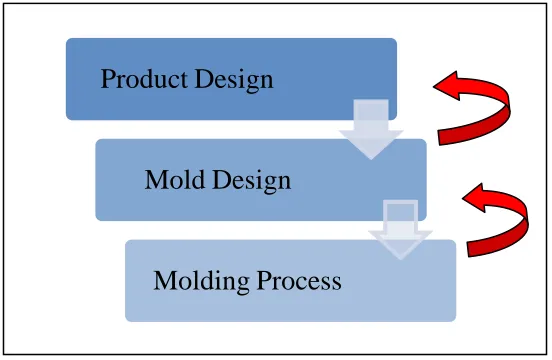
Typically, the process flow of develop a molded part using injection molding in a current practice is product design, mold design and mold process as shown in Figure 1.1. Basically, cavity layout design depends mostly on engineer expert and knowledge. For example, for the layout patterns, the criteria to select the suitable layout pattern for design are mainly dependent on working surroundings, conditions and demands of the customer and above all based on engineer skill and experience. The design of mold is also influence by several other factors such as part mold material, geometry, parting line and number of cavities per mold. All this contribute to the quality of the molded product as well as production efficiency.
[image:18.612.194.470.352.532.2]
Figure 1.1: Conventional Method of Injection Molding Process.
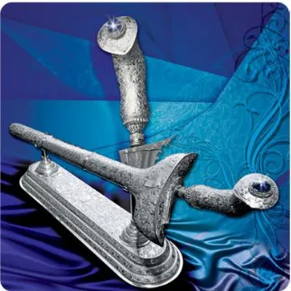
In this project, a new design for plastic part which is souvenir part for graduation day is selected. Keris Panjang as shown Figure 1.2 will be the main design of the product. This Keris Panjang is the representation of the power of the University. To overcome the problem that may arise during development develop this part, a systematic way is introduced.
Product Design
Mold Design
3 Figure 1.2: Keris Panjang is Symbol of The University Authority.
The systematic way used the application of CAD/CAE and CAM by consider the plastic part design, mould design and injection molding parameter and others factors as early as possible in the design stage by get rid of all kind of problems with optimal values without any repetition of production cycle. This systematic way can reduce time consuming, minimizing cost, and ideal use of labor time and in time dispatch with high
4 1.1 PROBLEM STATEMENT
The current plastics industry is under great pressure to survive the competing
environment, manufacturing leading times and desire to shorten design process because of the globalization of the market and high demand of the product (Raghavendra et al, 2015). The current processes of injection mold industry use the try an error method on fabricating a mold. If any problem occurs in any stage of the process, then the whole cycle has to be redone on trial an error method which will rise in overhead costs, unproductive working time, waste of labor, the dissatisfaction of customers because of delay in dispatch of product date and so on (Prakash, 2014).
5 1.2 OBJECTIVES
(a) To develop 3D molded part for injection molding (souvenir for graduation
day).
(b) Fabricate the core and cavity of the mold. (c) To analyze injection molding parameter.
1.3 SCOPES
(a) Design a new plastic part by taking the design concept from existing parts. (b) The parts design should be considered manufacture in two plate mold. (c) The core cavity of the part will consider the available of existing mold
6
CHAPTER 2
LITERATURE REVIEW
2.0 Introduction
In this chapter, the data, analysis and information about development of plastic molded part will be stated. Development of plastic molded generally contributes three stage processes which is product design, mold design and injection molding process.
Each stage has a different way to be complete.
2.1 Traditional Injection Molding Processs
7 once again rebuilt by considering the shrinkage and injection parameter. Consequence of this, the result indicated that conventional method will consume more time and also
increases the cost of machining and delay in dispatching the product. If change in design happens before pre-production and after production by trial an error method then there will be a severe increase in design change cost which effects on cycle time, waste of raw material, increase in process time and wastage of labor cost. This lack of fundamental engineering analysis during mold design frequently result in mold that may fail and require extensive rework, produce molding of inferior quality and less cost effective than may have been possible. Conventional method of plastic injection molding is based on the type of artifact, hence the numbers of trials are required to understand like injection time, injection pressure, temperature, clamping force and shear stress (Prakash, 2014). These trials are once again repeated if design is changed.
2.2 Systematic Molding
With the advances in computer technology and artificial intelligence, efforts have been directed to reduce the cost and lead time in the design and manufacture of an injection mold to become more systematic process. Prakash, 2014, expressed that systematic molding is where the product development has changed from the traditional serial process of design, followed by manufacture, to a more organized concurrent process where design and manufacture are considered at a very early stage of design. The pictorial view of systematic concept with computer aided engineering method is
8 studies have also been made on improving the design of specific components of an injection mould.
i. Computer Simulation for Finding Optimum Gate Location in Plastic Injection Molding Process by Babu and Vardan (2013). In this project an analysis has been performed to investigate different gate locations for a head light cover of an Alto car a plastic component. Plastic advisor simulation tool from Pro/E was used for the analysis to optimize the gate location with slightest defects and it requires less time to reach a quality result with no material waste as compared with conventional trial error method.
ii. Sustainable injection molding: The impact of materials selection and gate location on part warpage and injection pressure by Huszar et al. (2015). This research comes up to on how the warpage (i.e. part deflection) and injection pressure of an intricate. The computational work used Moldflow Insight's “Fill + Pack +Warpage” analysis sequence to investigate the molding characteristics
of a partially symmetrical, hollow geometry using four potential gate locations geometry could be minimized by selecting an maximum thermoplastic material and injection gate location (through which the molten plastic flows into the cavity). The numerical analyses for mold filling considered four gate locations along with a PP (polypropylene), PS (polystyrene) and a fibre-filled PP material. Each had different shrinkage characteristics, mechanical property and
viscosity.
iii. Gating System Design Optimization for Injection Molding by Dr. M P Singh et al. (2015) develop a system with the help of CAD or CAM which facilitates the user to work on injection molding operations starting from the cavity to the selection of gates and then to the efficiency of runner and finally to sprue. This results in time reduction of designing process and to a certain extent also reduces manufacturing cost.