University of Southern Queensland Faculty of Engineering and Surveying
“Effects and Controls of Lateral Refraction in Underground Coal Mines”
A dissertation submitted by
Logan Mohr
In the fulfilments of the requirements of
Course ENG4111 and ENG4112 Research Project
Towards the degree of
Bachelor of Spatial Science (Surveying)
Abstract
Environmental conditions in underground coal mines effect lateral refraction when surveying with a regular theodolite. Xstrata Coal’s Oaky North Mine situated 26Km east of Tieri in Central Queensland’s Bowen Basin has overcome these environmental conditions by utilising gyrotheodolites to control the underground survey network. This project studies the environmental conditions effecting lateral refraction and how Oaky North Mine utilises gyrotheodolites to control the underground survey network.
Oaky North Mine is an underground longwall coal operation, producing approximately 5 million tonnes of sub-bituminous, medium volatile coal per annum. Two pairs of parallel tunnels (gateroads) with cross cuts every 100m are driven using a continuous miner for a length of approximately 3.4 Km. These gateroads form the maingate and tailgate of the longwall block.
The demand for an accurate underground control network is high. Typically, accuracies of ±50mm are expected allowing a breakthrough tolerance of ±100mm. The ability to establish accurate control networks and perform associated surveys is restricted by lateral refraction. The path of light through the atmosphere is influenced by the inhomogenities of the refractive index. This refractive effect deteriorates the pointing accuracy of survey lines. Currently, there is no available method to accurately correct these systematic errors.
This project investigates whether literature research supporting the use of a gyrotheodolite, will improve breakthrough errors of an open ended traverse or when compared to the readings from TCRA 1203 vary sufficiently to be outside accepted tolerances.
University of Southern Queensland
Faculty of Engineering and Surveying
ENG4111 Research Project Part 1 &
ENG4112 Research Project Part 2
Limitations of Use
The Council of the University of Southern Queensland, its Faculty of
Engineering and Surveying, and the staff of the University of Southern
Queensland, do not accept any responsibility for the truth, accuracy or
completeness of material contained within or associated with this dissertation.
Persons using all or any part of this material do so at their own risk, and not
at the risk of the Council of the University of Southern Queensland, its
Faculty of Engineering and Surveying or the staff of the University of
Southern Queensland.
This dissertation reports an educational exercise and has no purpose or
validity beyond this exercise. The sole purpose of the course pair entitled
"Research Project" is to contribute to the overall education within the
student’s chosen degree program. This document, the associated hardware,
software, drawings, and other material set out in the associated appendices
should not be used for any other purpose: if they are so used, it is entirely at
the risk of the user.
Professor Frank Bullen
Dean
Certification
I certify that the ideas, designs and experimental work, results, analyses and conclusions set out in this dissertation are entirely my own effort, except where otherwise indicated and acknowledged.
I further certify that the work is original and has not been previously submitted for assessment in any other course or institution, except where specifically stated.
Logan Mohr
Student Number: w0029287
___________________________________________________ Signature
Acknowledgements
The author wishes to acknowledge the support and advice given by Shane Simmons as a mentor, Xstrata Coal Oaky North Survey Department and C R Hutchison & Co. Principal, Chris Hutchison.
Contents
Abstract I
Disclaimer II
Certification III
Acknowledgements IV
Contents V
List of Figures VII
List of Tables VIII
List of Appendices IX
Abbreviations X
Chapter 1... 1
INTRODUCTION...1
1.1 Outline of Study ...1
1.2 Introduction ...1
1.3 The Problem ...2
1.4 Justification ...3
1.5 Research Aim...4
1.6 Research Objectives ...4
1.7 Conclusion ...4
Chapter 2... 6
LITERATURE REVIEW...6
2.1 Introduction ...6
2.2 Defining Lateral Refraction...6
2.2.1 Refraction ...6
2.2.2 Refractive Index...7
2.2.3 Lateral Refraction...7
2.2.4 Horizontal Refraction ...8
2.3 The Gyroscope Principle ...8
2.3.1 Precession – Gyroscope Principle ...9
2.3.2 North Seeking Gyroscope ...9
2.4 The DMT Gyromat 2000...10
2.5 Accuracy Comparison with Other Instruments ...13
2.7 Traditional Survey Methods in Surrounding Mines ...15
2.8 Deficiencies in the DMT Gyromat 2000...15
2.9 Conclusion ...16
Chapter 3... 17
METHODOLOGY...17
3.3.2 Risk Assessment ...19
3.3.3 Equipment Inventory...19
3.3.4 Data Collection...20
3.4 Surveys...21
3.4.1 Surface Baseline ...21
3.4.2 Underground Baselines ...22
3.5 Conclusion ...23
Chapter 4... 24
RESULTS AND ANALYSIS...24
4.1 Introduction ...24
4.3 The Networks Analysed ...24
4.4.1 SMG6 Development Panel...25
4.4.2 300 Panel...27
4.5.1 SMG6 ...29
4.5.2 300 Panel...32
4.6 The Suitability of a Gyromat 2000 as a Lateral Refraction Control...34
4.7 Conclusion ...34
Chapter 5... 35
CONCLUSION...35
5.1 Summation ...35
5.3 Recommendations...36
5.4 Conclusion ...37
REFERENCES...38
APPENDIX A ...40
APPENDIX B ...41
APPENDIX C ...42
APPENDIX D ...43
List of Figures
Number Title Page
Figure 1.1 Surveying underground at Oaky North Mine...1
Figure 1.2 Oaky North mine layout...2
Figure 2.1 Refreaction ...6
Figure 2.2 Measuring angular refraction ...7
Figure 2.3 Measuring horizontal refraction...8
Figure 2.4 Gyroscope ...9
Figure 2.5 Gyromat 2000 underground ...10
Figure 2.6 Integration method for Gyromat 2000 ...11
Figure 3.1 Gyromat 2000 with top mounted T2...22
Figure 4.1 SMG6 standard deviations ...26
Figure 4.2 SMG6 adjustment without Gyro observations...27
Figure 4.3 300 Panel standard deviations...28
Figure 4.4 300 Panel adjustment without Gyro observations...29
Figure 4.5 SMG6 standard deviations with Gyro observations...31
Figure 4.6 SMG6 adjustment with Gyro observations ...32
Figure 4.7 300 Panel standard deviations with Gyro observations ...33
List of Tables
Number Title Page
2.1 Measuring accuracies of Gyromat 2000 12
List of Appendices
Number Title Page
A Project Specification 40
B Risk Assessment for Using Portable Electrical Equipment 41
C Standard Operating Procedure for Using Portable
Electrical Equipment 42
Abbreviations
The following abbreviations have been used throughout the text and references:-
DMT Deutsche Montan Technologie PGD Personal Gas Detector
SMG6 South Main Gate 6
Chapter 1
Introduction
1.1Outline of Study
. (Wilkins, 2004)
The above statement suggests the need for research into lateral refraction and how its effects can be overcome or rectified in underground surveying. The scope of this study is detailed in 1.5 Research Aim and 1.6 Research Objectives.
1.2 Introduction
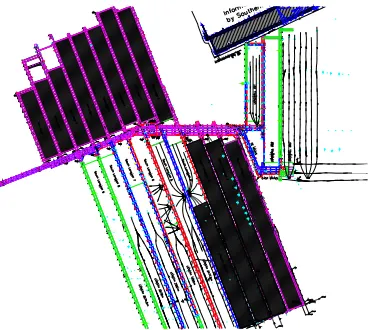
Some of the hardest conditions a surveyor is likely to encounter are those associated with an underground coal mine environment. It is the very nature of underground coal mining, which dictates surveyors work in confined spaces, with conditions that are less than ideal for accurate control surveys, as evidenced in Figure 1.1 below.
Figure 1.1 Surveying underground at Oaky North Mine
Environmental conditions that constantly affect these long traverse lines include; turbulent air flow created by the forced ventilation systems. Furthermore, the uneven mixture of gases and temperature variances in the air associated with nearby plant cause light rays to be refracted from the direct line of sight intended for observation. (Hutchison, 2006) Subsequently, the compounding factors listed above required an investigation into possible solutions, in order that a surveyor can attain more accurate readings.
This project will investigate a solution to the variances in readings caused by lateral refraction by utilising the DMT (Deutsche Montan Technologie) Gyromat 2000 gyrotheodolite. The resultant information gained from the DMT Gyromat 2000 will be compared with a Leica TCRA 1203 totalstation and analysed to identify errors associated with lateral refraction. Following the analysis, the findings will inform the design of a methodology and guide recommendations, with a view to minimising the problem of refractive errors, in underground surveying.
1.3 The Problem
Surveyors in underground tunnels experience difficulties obtaining an accurate reading, because their line of sight is affected. Hutchison (2006), identifies the cause stating;
[image:13.595.241.426.74.239.2].
This phenomenon poses problems such as; misaligned tunnel heading directions and incorrect underground locations. In terms of an underground coal mine, these misaligned tunnel heading directions and incorrect underground locations seriously impact on a mine’s productivity in the current commodities market boom. Competitiveness within the commodities boom has evidenced the emergence of at least 14 satellite operations in the Central Highlands region of the Bowen Basin capitalising on the boom (Central Queensland News, 2007).
In such a highly competitive market, the mines operations manager deems it essential that accurate surveys are carried out in a timely manner, in order to minimise production disruption associated with revisiting, due to errors. The seemingly high costs associated with carrying control underground are insignificant, when compared to the cost of lost production for a multimillion dollar operation. Engineering issues associated with the inaccurate headings, caused by lateral refraction, result in the conveyor being unable to track in a straight line. Associated with the necessity for straight tracking is the issue of a longwall’s roof supports becoming wedged between diverging gate roads. As this machine cannot be driven backwards, production ceases instantly, until a salvage operation is mounted to remove the roof supports and shorten the face width, to allow mining to recommence. Such a stoppage effectively ceases production for a month.
1.4 Justification
Holing into abandoned workings is an occupational health and safety issue, potentially risking miner’s lives and mine closure, whereas delays in continuous longwall production due to inaccurate headings, at current market prices, cost an operation approximately $100,000 an hour in lost revenue. There is also the increased possibility of a strata failure that could halt production, from a few weeks to several months. A strata failure has the potential to halt the longwall, and once stationary for a period of time, the weight from the goafing roof throws weight forward, resulting in shield convergence and face fracturing.
1.5 Research Aim
The aim of this research is to determine the accuracy of results obtained from a DMT Gyromat 2000 in relation to those obtained from a Leica TCRA 1203 in overcoming lateral refraction effects in underground surveying.
1.6 Research Objectives
To achieve the research aim, this project will employ the following objectives:
1. Evaluate current control surveying methods used within the coal mining industry generally and specifically at Oaky North Mine.
2. Identify the conditions that cause lateral refraction in underground mines and analyse the effects of lateral refraction
3. Collect and analyse gyroscopic information and calculate variance to tunnel heading directions in comparison with those readings from a Leica TCRA 1203 4. Determine if the readings gained by a Gyromat 2000, compared to the readings
from TCRA 1203 vary sufficiently to be outside accepted tolerances.
5. Make recommendations that counteract the effects of lateral refraction in underground mines.
1.7 Conclusion
Chapter 2
Literature Review
2.1 Introduction
In order to better understand the effects of lateral refraction on an underground mine survey and consequently determine the suitability of a DMT Gyromat 2000for reducing lateral refraction’s effects, this chapter will review pertinent and where possible current literature, relevant to both lateral refraction and the DMT Gyromat 2000in underground tunnelling as opposed to a Leica TCRA 1203.
2.2 Defining Lateral Refraction
In order to understand the effects of lateral refraction, the terminology needs to be defined.
2.2.1 Refraction
[image:17.595.230.416.522.593.2]Refraction is the change in direction of a wave due to a change in its velocity. This is most commonly seen when a wave passes from one medium to another. Refraction of light is the most commonly seen example, but any type of wave can refract when it interacts with a medium, for example when sound waves pass from one medium into another.
Figure 2.1 Refraction
enters and leaves glass; understanding of this concept led to the invention of lenses and the refracting telescope (Wikipedia, 2006).
2.2.2 Refractive Index
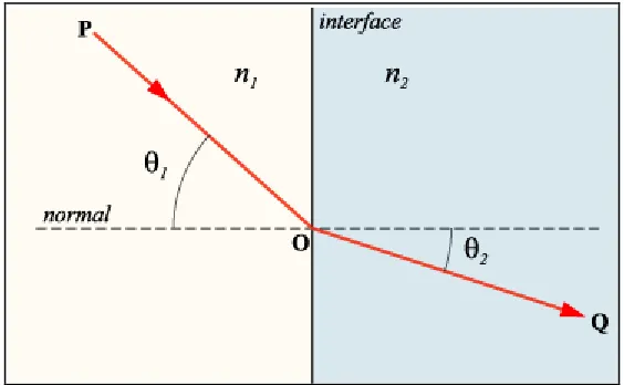
[image:18.595.185.467.320.494.2]The refractive index of a material is the factor by which the phase velocity of electromagnetic radiation is slowed in that material, relative to its velocity in a vacuum (Wikipedia, 2006). If a ray of light is incident at an angle to the surface the ray is bent as it enters the new medium. The angle 1 is the angle of incidence and the angle 2 is the angle of refraction (Giancoli, 1998). This refractive index explains how varying temperatures and air compositions distort light rays during lateral refraction.
Figure 2.2 Measuring angular refraction
2.2.3 Lateral Refraction
Lateral refraction is not a commonly understood phenomena among surveyors and therefore its effects are not widely known. Johnston (1997) states;
2.2.4 Horizontal Refraction
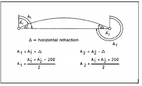
[image:19.595.210.447.179.322.2]Korittke (1996), identified the influence of horizontal refraction, related to errors evidenced in the construction of The Channel Tunnel and provided an azimuth determination using a DMT Gyromat as evidenced in Figure 2.3 below.
Figure 2.3 Measuring horizontal refraction
Kahem and Faig (1988), also recognised the effects of refraction for surveyors in tunnels and recommended the use of various instruments including a gyrotheodolite. In order to determine the suitability of a DMT Gyromat 2000, the underlying principle of a gyroscope is explained.
2.3 The Gyroscope Principle
Figure 2.4 Gyroscope
2.3.1 Precession – Gyroscope Principle
Precession is the term used to describe the movement of the axle of a gyroscope under the influence of an external force. If one, for reasons of simplicity, compares a gyroscope with a toy top, we know that the top at rest will fall down on the ground due to the gravitational force exerted on the top. However, if the top is rotating around its symmetry line, then the top will not fall down and the symmetry rotation axis will move in a conic around a vertical line. This well-known phenomenon is called regular precession of a top. If a force is applied to the spinning rotor of a gyroscope by moving one end of its axle, the gyroscope will be displaced at an angle of 90 degrees from the applied force (Lewen, 2006).
2.3.2 North Seeking Gyroscope
2.4 The DMT Gyromat 2000
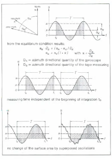
[image:21.595.193.460.233.498.2]Deutsche Montan Technologie (DMT) is the market leader in gyrotheodolite technology. The Gyromat 2000 is fully automated and is a single handed operation (Korittke, 1997). The following information from Kroittke’s FIG-Symposium paper (1997) gives a synopsis of the Gyromat 2000 identified in Figure 2.5 below and its capabilities.
Figure 2.5 a Gyromat 2000 underground
!"
# $ %
% #
# #
# & %
!' ( $) & **+ ',--.
/ 0 1
/ " 23 " '42 /" 443 " '52 / " 543 " 6'2
7 %
8 6 9
[image:22.595.232.429.55.334.2]This means the area of integration is not affected by natural oscillations such as the case of equipment vibrating the floor, in an underground coal mine.
If the gyro is bumped or the rectifier detects movement, it induces an oscillation drift.
:; &< 6222 1
' ' 6 6 = = !/ " >43 923$
0 - ,
Because the Gyromat 2000 has short measuring times, measurements should be performed twice for redundancy.
GYROMAT 2000 65 Jobs
665 Mean values 1.728 Measurements
[image:23.595.233.391.319.427.2]SA ~ ± 0,7 mgon == 211
Table 2.1 Measuring accuracies of Gyromat 2000
A Gyromat 2000’s accuracies shown above in Table 2.1 indicate that using the
results from tunnels and mines, a standard deviation SA for a single azimuth determination can be calculated Korittke (1997).
2.5 Accuracy Comparison with Other Instruments
There are some instruments that are unsuitable for underground surveying and will automatically be precluded from the comparison as listed in Table 2.2 below.
INSTRUMENT UNSUITABILITY REASON
GPS Obstructed view of the sky
[image:24.595.170.483.159.239.2]3-D Laser Scanner Not orientated towards traversing Can not change battery underground
Table 2.2 Instruments unsuitable for underground surveying
Hathaway and Slaton (2004: 6), reporting on the Nancy Creek Sewer Relief Project in Atlanta used a DMT Gyromat 2000, as they believed it was the most accurate machine available and recognised the gyrotheodolite’s ability to produce an azimuth determination underground due to the non viability of GPS. Recognising previous research on lateral refraction by Chrzanowski (1981) and Heister (1992), Greening et al (1993) concluded that a DMT Gyromat 2000 was the optimum piece of equipment to overcome refraction errors, recommending;
??@
1
1
" =2A
B 1 " 2 5A =
B 1 " C!2 4 $D(!' $D?D
E 1< F G
2.5.1 Totalstation Positioning Systems
Angle measurement
Type 1201 Type 1202 Type 1203 Type 1205
! "#$ % &
' ( ) * * + , -. % -. % -. % -. % # ** * ' ( * / * Distance measurement 0 120
3 4 *
105-' 1'2
0 4 * ! /
! ( **
#( ) *
# 6 7
8 6 7 9
: *, 6 7 ;
! "#$ %
[image:25.595.103.544.66.334.2]&-2( * / ! ) 4
Table 2.3 Total station positioning systems specifications
2.5.2 Alternatives to the Current Oaky North Survey Process
Of the theodolites investigated, the most suitable alternative to the one currently used at Oaky North would be the Leica TCRA 1201 which is a 1” totalstation with specifications evidenced in Table 2.3 above.
2.6 Control Survey Method at Oaky North Mine
Greening et al (1993) as stated in Chapter 2.5 recognises the value of zig-zag traversing as a means of overcoming lateral refraction in tunnel surveying. This is however, not possible in an underground coal mine because as vertical stresses increase, as a result of the mining process, ribs spall (crush out), effectively destroying any wall stations.
2.7 Traditional Survey Methods in Surrounding Mines
While the literature supports the use of a gyrotheodolite as a means of overcoming the effects of lateral refraction, it is pertinent to review surveying practice in surrounding underground mines. Through communications with the local surveying network and personal experience, knowledge of surveying practice in other mines was gained. Rio Tinto’s Kestrel mine utilises a Wild T1000 for its underground network while BMA Crinum and Gregory mines use TCRA1103 as does Oaky No1. These mines experience reading variances of 10 – 30” which they directly attribute to lateral refraction. Coincidently, these mines all avail themselves of the services of C R Hutchison & Co’s Gyromat 2000 on a rotational basis when in the Bowen Basin, as a means of correcting reading errors associated with lateral refraction (Morris, 2006).
2.8 Deficiencies in the DMT Gyromat 2000
DMT do not publish any literature relating to deficiencies with their Gyromat 2000, however, the following were issues raised in research:
1. Hathaway and Slaton (2004), recognised that the instrument is relatively sensitive, in that takes 45 minutes to acclimatise each time it is taken underground.
2. Hamilton (2002), identified prohibitive cost as a drawback to regular use of a gyrotheodolite.
4. The Gyromat 2000 is battery operated and is therefore required to be signed into the Uncertified Portable Electrical Equipment (UPEE) register before being taken underground. Consequently, the operator/supervisor must carry a Personal Gas Detector (PGD) at all times in accordance with SOP0202OCN refer to Appendix C.
5. In the event of the Gyromat 2000 being damaged on site or in transit, it has to be returned to Germany for repairs. As the repair process can feasibly take up to 3 months, there is potential for project delays or the risk of exacerbating refraction errors if solely reliant on readings from a regular theodolite.
2.9 Conclusion
Chapter 3
Methodology
3.1 Introduction
The findings of the literature review in Chapter 2 have been considered in developing the best approach to achieving the project’s objectives previously outlined in Chapter 1. Based on research findings, a Gyromat 2000 is considered the most effective technology available with which to achieve these objectives. While conducting this survey project with a Gyromat 2000, the obtained data will be cross referenced against data from a traditional survey. The data from both surveys will be compared to determine if variances in readings vary sufficiently to be outside accepted tolerances. By doing the comparison in reading variances, the efficiency of a Gyromat 2000 over a traditional survey will either be confirmed or disproved. The literature review has confirmed a procedural format and project methodology
3.2 Procedural Format
a. Research:
• lateral refraction theory, so as to understand the phenomena’s effects on underground surveying. The findings of the research have been identified in Chapter 2.2 - 2.3.2. as being that lateral refraction is a phenomenon that effects traverse lines in tunnels.
• theodolites generally, to determine those that are suitable for underground surveying as opposed to those that are not. The findings of the research have been identified in Chapter 2.4 - 2.7. Specifically, theodolites suited to underground surveying include totalstations as opposed to GPS and laser scanners.
b. Research Analysis:
c. Strategy:
• develop a cost analysis for utilising a Gyromat 2000 over 12 hours • secure the services of C R Hutchison & Co. As they own the only
Gyromat in Australia, this will take some organising
• complete a risk assessment for underground use of the battery operated Gyromat 2000 (Appendix B)
• complete equipment inventory
d. Data Collection:
• conduct the trial survey, recording data from the Gyromat 2000. At the same time consideration will be given to atmospheric and locational conditions
e. Data Analysis:
• Compile the data obtained from both surveys and do a comparison analysis of the results from both machines using Star*Net. T-test analysis can be used for data analysis for the purpose of this project.
• Cross reference the results analysis against literature review findings to determine accuracy and validity
f. Conclusion:
• Reflect on results obtained and make recommendations regarding the control of lateral refraction in underground coal mines
3.3 Research Method
The research method will commence at Procedural Format item c. – Cost Analysis
3.3.1 Cost Analysis
the proposed booking was confirmed with C R Hutchison & Co. to hire the Gyromat 2000.
In order to reduce costs associated with the hire, transport and operation of the Gyromat 2000, to Central Queensland from Newcastle, surrounding operations are queried as to whether they will be able to utilise the services of the Gyromat 2000, while in the area.
3.3.2 Risk Assessment
The Coal Mining Safety & Health Regulation (1999) Section 202 outlines the
procedures for taking Uncertified Portable Electrical Equipment (UPEE) underground. This requires a risk assessment to be completed prior to development of a standard operating procedure (SOP).
As the practical component of the project will be conducted in the underground environment, all necessary OWPHS procedures will be followed. Furthermore, the operator will need to show proof of a current negative drug screen and hold a current underground contractors induction certificate.
A risk assessment (RA0202OCN) has been carried out to assess the hazards associated with the use of UPEE in the underground environment at Oaky North Mine, aimed at reducing the risk to a minimum (Appendix B).
Prior to the commencement of any new or different tasks, a SLAM (Stop, Look, Assess and Manage) or formal SLAM is carried out to identify any possible hazards associated with carrying out the task. The SLAM booklet involves some tick questions and writing down observed hazards and controls.
3.3.3 Equipment Inventory
• Accommodation and transport for gyro operator • Computer with Microsoft excel
• 50hrs staff time
• 2 sets of legs – 1 for target and 1 for backsight • Leica ZNL plummet
• Targets
• Umbrellas to stop wind buffeting the Gyromat 2000
Of the equipment identified, accommodation is the most lucrative. Due to the commodities boom, demand for accommodation far outstrips supply. This necessitates all planning for data collection to pivot around accommodation availability. Unfortunately if the operator cannot be provided with accommodation, the gyro survey cannot take place.
3.3.4 Data Collection
Before the Gyromat 2000 arrives on site, the co-ordinates for the proposed lines are sent to the survey consultant, thereby allowing the calculation of grid convergence for each line. Once the observation lines have been agreed, a notification is placed into the weekly plan that the surveyors will have the section closed for the duration of the survey.
Once on-site, the Gyromat 2000 will be setup over two previously observed points to gain a current site swing. Before the Gyromat 2000 can go underground the batteries are discharged then recharged. This process ensures maximum time underground with fully charged batteries, as the NiCd batteries were nearing the end of their service life.
Figure 3.1 Gyromat 2000 with top mounted T2
3.4 Surveys
For the purposes of this project a surface baseline and two separate underground baselines were surveyed using the Gyromat 2000.
3.4.1 Surface Baseline
As mentioned in 3.3.4, a surface base line survey is conducted to orient the machine to the site and establish a site specific correction value.
The surface baseline was surveyed early in the morning to minimise temperature change on the Gyromat 2000 and reduce the effects of heat shimmer. The Gyromat was setup over RHB2 sighting RHB3 at 7:00am. The weather was sunny with a light breeze.
office overnight the next two measurements at RHB2 were completed by 7:45am with no temperature warnings and the gyro moved to RHB3.
The first measurement at RHB3 commenced at 8:20am and was complete by 8:40am. Once the gyro temperature had stabilized there were no temperature warning lights and the two drops at RHB3 were completed within 20 minutes with no problems.
3.4.2 Underground Baselines
Of the two survey lines to be observed, the first was in a standing panel that has been left (SMG6) while another area of the mine is developed. This is ideal for the survey as there will be no traffic trying to pass the instrument and legs.
Once at the site the Gyromat 2000 case is opened to allow the units temperature to equalise with the ambient temperature. The survey legs were setup with the zenith plummet and tribrach underneath the control station. Once a close position was found using the plumb bob the plummet was used to move directly under the station. The plummet was then removed and replaced with the Gyromat cradle. The cradle was levelled using an engineer’s spirit level. The gyro was then lowered into the cradle so that the reference arrow was orientated towards north.
Once the gyro is levelled and screwed down it is turned on and the latitude of the station is entered in through the menu. Once the target has been setup under the foresight station the gyro is turned on and the automated program is run. During the next 7 – 9 minutes the gyro moves though each of the four steps to orientate itself towards true north. Due to the mine site latitude being approximately S23.05° the oscillation time of the gyro is faster than at lower latitudes. This saw measurement times of approximately 7.5 mins.
caution. In the case of either a temperature or drift warning light the measurement should be taken again. This instance saw no warning lights, confirming a successful reading.
The second survey line is in a current priority panel (300 Panel) that can not be stood down. Planning with the development coordinator saw that the survey was able to complete the gyro readings, with no disruption from vehicle movements.
At each survey line the conditions will be noted, along with any plant and ventilation control devices in the area. On completion of the survey campaign, preliminary results will be supplied, to give a close approximation of the observed azimuths. The final results will be posted to the survey department within two weeks. These results will show the deviation and observed azimuths for each gyro line. If any differences are found the station data base will be adjusted using an angular adjustment weighted on distances.
It is expected to find that as the ventilation in the headings passes the section transformers, it changes the refractive index of the air due to increased temperature and turbulence. It is also expected to find that mobile plant parked on the rib line interferes with the flow of the ventilation and temperature to produce the same effects as transformer cut throughs.
3.5 Conclusion
Chapter 4
Results and Analysis
4.1 Introduction
The object of this chapter is to compare the resulting azimuth observed using the Gyromat to the azimuth carried forward using traditional survey traversing. The two traverses will be processed using a least squares adjustment in the Star*Net Package. Each network will be processed first with the conventional traversing method before being processed holding the gyro observations fixed. Once all traverse observations have been entered into Star*Net, the network is processed and errors for the observations and points are calculated.
The data will be analysed in accordance with Chapter 1.6 objectives 2 -5, as a means of verifying or refuting research data supporting Gyromat 2000’s accuracy in counteracting the effects of lateral refraction. Particular interest will be given to whether the readings gained by the Gyromat 2000, compared to the readings from a TCRA 1203 vary sufficiently to be outside accepted tolerances.
4.2 Surface Baseline Results
These observations are performed between two known surface primary control points to allow the Gyro operator to gain a site specific swing correction value. After reading between RHB2 and RHB3 a site swing of -14.6” was established to correct Gyromat 2000 readings to align with the mines grid datum.
4.3 The Networks Analysed
Leica ZNL plummet, to give better position accuracy, rather than using a plumb bob on a string as used for working surveys.
4.4
Network Analysis without Gyro Observation
The following Figures 4.1 and 4.3 graph the standard deviations of the stations easting and northing for SMG6 and 300 Panel, starting with SMG6.
4.4.1 SMG6 Development Panel
As previously identified in Chapter 3.4.2, this development panel has been left while another area of the mine is developed. This development panel had advanced
approximately 2.7km before the Gyromat 2000 was ordered to come on site. Figure 4.1 below indicates there were ten check survey stations that had been read to, since the previous gyro observation.
SMG 6 Station Co-ord Standard Deviations
[image:36.595.117.527.455.594.2]0.01 0.0150.02 0.025 0.03 0.0350.04 0.045 0.05 m et er s (m ) Easting Northing
Figure 4.1 SMG6 Standard Deviations
Figure 4.2 below shows the error ellipses for each stations observation.
Figure 4.2 SMG6 Adjustment without Gyro observations. Ellipse exaggeration = X5000
4.4.2 300 Panel
In Chapter 3.4.2, this development was identified as a current working panel. 300 Panel is the latest development heading started. Due to the short length of this block and the short period of time it has been operating, the panel had only advanced 500m when the gyro was brought on site. As identified in Figure 4.3 below, there were six check survey stations having been read to, with no previous gyro observation.
300 Panel Station Co-ord Standard Deviations
0 0.0005 0.001 0.0015 0.002 0.0025 0.003
668 1266 1264 1290 1295 1587
Stn#
M
et
er
s
(m
)
[image:38.595.122.531.210.398.2]Easting Northing
Figure 4.3. 300 Panel standard deviations
Figure 4.4 300 Panel adjustment without Gyro observations Ellipse exaggeration = X5000
4.5 Network Analysis with Gyromat 2000 Observation
As mentioned previously, gyro observations will be added to the network adjustment as a fixed observation line. The data used to adjust the previous networks will remain with the exception of the addition of the gyro observations as an additional control file.
The main reason for including the gyro observation is to adjust the traverse line leading to the observed gyro line. With the addition of the gyro observation new corrected values for the bearings and resultant coordinates will be generated as part of the list file.
Due to time constraints there is only ever one set of gyro observations performed in each panel. This consists of two gyro measurement performed at each end of the observed line. The claimed error of the Gyromat 2000 is 1mgon (0.3”) which through extensive use the operator believes to be achievable (Hutchinson, 2006).
Surface baseline calibrations showed that the observed direction between RHB2 and RHB3 had an accuracy of 2.9” this is well above the stated1” accuracy of the Gyromat 2000.
4.5.1 SMG6
The Gyro observation in the SMG6 panel showed that the bearing between the observation stations was in fact 21.4” less than the gyro observation. This error would equate to approximately 200mm over the 2Km length of the panel. With a deviation tolerance of 150mm, this deviation is outside the accepted tolerance.
SMG 6 Station Co-ord Standard Deviations Gyro Adjusted
0 0.01 0.02 0.03 0.04 0.05 0.06
1481 1497 1516 1526 1540 1550 1554 1563 1574 1584 Stn #
m
et
er
s
(m
)
Easting Northing
[image:41.595.120.535.58.256.2]Figure 4.5 SMG6 standard deviations with Gyro observations
Figure 4.5 shows that the stations have deviated from the design centreline. However, with the addition of the Gyromat 2000 observations to the list file, the deviations are no longer increasing and become static. This is in line with processing the network
4.5.2 300 Panel
With the relatively short distance that 300 Panel had advanced before the gyro was bought on site, there was a 7.7” variation between the control survey value and the observed gyro value. Again the control survey value was less than the gyro value. This tends to indicate that working surveys have a tendency to move to the right when heading inbye (mining terminology for looking into the pit). 7.7” in angular deviation relates to 18mm after 500m which is well within mining tolerances.
300 Panel Station Co-ord Standard Deviations Gyro Adjusted
0 0.0005 0.001 0.0015 0.002 0.0025
668 1266 1264 1290 1295 1587
Stn #
M
et
er
s
(m
)
Easting Northing
[image:43.595.120.534.242.432.2]Figure 4.7 300 Panel standard deviations with Gyro observations.
Figure 4.8 300 Panel adjustment with Gyro observations Ellipse exaggeration = X5000
4.6 The Suitability of a Gyromat 2000 as a Lateral Refraction Control
As previously stated, based on the literature review, a Gyromat 2000 was deemed the most accurate machine for use in underground tunnels, toward the control of lateral refraction. The results obtained and analysed above in Chapter 4 show that the use of a Gyromat 2000 provides an effective control of lateral refraction in underground coal mines. The variances obtained in the surveys using a Leica TCRA 1203 compared to the Gyromat 2000 were determined using a t-test with a confidence level of 95%. It was found that the Gyromat 2000 had a standard deviation of 1.3” which is 0.3” greater than the stated achievable accuracy compared to the TCRA1203’s standard deviation of 2.8” which is less than the stated 3” accuracy (Appendix E). These values confirm that the Gyromat 2000’s ability to detect reading errors, makes it an effective control mechanism for lateral refraction in an underground mine survey.
4.7 Conclusion
Chapter 5
Conclusion
5.1 Summation
The gyrotheodolite has been utilised in many tunnelling activities in the past and has recently been implemented into some underground coal mines on the premise that it is a valuable tool to control open ended traverses. This project showed that, by using a Gyromat 2000 to measure sight lines independent of previous traversing, the effects of lateral refraction can be corrected. These corrections can be applied to the traverse lines after the Gyromat data has been used in the Star*Net adjustment for the panel and new station coordinates will be calculated.
However, the gyrotheodolite is not intended to detect gross or systematic errors. This means, emphasis must be placed on good survey practice, as there is a reduced availability of redundant checks. If gyro observations are to be used in improving a control network, it is imperative that the observations themselves are corrected and computed in a manner that will minimise gross and systematic errors. One possible way to correct gross errors would be top use the totalstations ability to store all underground survey stations and use the Leica sets of angles program to read check survey angles. This program is an automated reading program that allows the user to specify the number of angles to be read and the stations to be read to.
Much of the available literature is based upon wall mounted stations, and as such, the ability to create a redundant network like this is not the case in underground coal mines, due to the susceptibility of rib spall (wall failure). There is scope to investigate a better roof station layout suitable to underground coal mining that allows for increased redundancy.
refraction. As the discrepancy of 2” is smaller than the stated 3” accuracy of the TCRA 1203, the surveyors are unable to measure more accurately than the error.
Currently, Oaky North mine’s lateral refraction control methodology is to hire the services and Gyromat 2000 of C.R. Hutchison and Co. This is done on a needs basis, associated with the availability of the Gyromat and the status of current mining operations, dictating when access to the panels can be gained.
5.3 Recommendations
Through the research and practical work carried out in the completion of this project I have found that there are many variables that require further study. One significant area for further investigation in developing a methodology to overcome lateral refraction would be strategies to minimise the conditions which cause lateral refraction in underground tunnels, as identified in the Chapter 2 literature review. This topic was outside the scope of this project but there is a need to gain a better understanding of temperature gradients in order to produce a methodology that will allow refraction to be corrected.
Because of the dynamic nature of the underground mine, the tunnel configuration relating to transformers, air pumps and venturi positions is constantly changing. Consequently, because of the temperature gradient for the tunnel cross section and the turbulence created from such devises, any correction values would need to be measured at the time of each measurement. This would prove to be very time consuming and would add to the amount of time a production panel is held up while surveys are performed. As this delay is not a viable option Oaky North mine will continue to utilise the Gyromat 2000 in order to fix the error after we have progressed down the heading.
reduced light environment. This machine is currently being under utilised because the users are not fully conversant with the machines capabilities and therefore reluctant to optimise its capacity.
It is further recommended that a trial be conducted with a 1” totalstation that would tighten the angle readings on check survey traverses. This would then be compared to the Gyromat 2000 readings on the next campaign. The objective would be to eliminate the need to hire a gyrotheodolite.
users are not fully conversant with the machines capabilities and therefore reluctant to optimise its capacity.
It is further recommended that a trial be conducted with a 1” totalstation that would tighten the angle readings on check survey traverses. This would then be compared to the Gyromat 2000 readings on the next campaign. The objective would be to eliminate the need to hire a gyrotheodolite.
5.4 Conclusion
This project has confirmed that in the current survey industry, particularly in the Bowen Basin, control surveying methods rely on a gyrotheodolite to detect pointing errors caused by lateral refraction from a totalstation. The specific gyrotheodolite utilised, the Gyromat 2000 is able to produce readings within accepted mining tolerance, as a lateral refraction control in underground mine surveying.
While this project’s objectives were addressed, the end result is that there is scope for a whole other project. A project aimed specifically at researching and developing
References
Bockem, B, Flach, P, Weiss, A, Hennes, M, 2000, REFRACTION INFLUENCE ANALYSIS AND INVESTIGATIONS ON AUTOMATED ELIMINATION OF REFRACTION EFFECTS ON GEODETIC MEASUREMENTS, viewed March 2006, Web site: http://www.geometh.ethz.ch/downloads/imeko.prn.pdf
Brunner, F, Grillmayer, E, 2003, On the temperature dependence of gyroscopic
measurements using the GYROMAT 2000, FIG XXII Congress Washington, D.C. USA viewed June 2006, Web site:
http://www.igms.tugraz.at/Publications/pdf/2002/eg_fkb_fig2002_preprint.pdf
Coal Mining Safety & Health Regulation (1999) Section 202, viewed October 2007, Web site:
http://www.legislation.qld.gov.au/LEGISLTN/CURRENT/C/CoalMinSHR01.pdf
Central Queensland News, Booming Ahead, viewed February 2007 Web site:
http://www.cqnews.com.au/localnews/storydisplay.cfm?storyID=3743924&thesection= localnews&thesubsection=
Kahmen, Heribert / Faig, Wolfgang , 1988, Surveying. Walter De Gruyter Inc, viewed August 2007, Web site:
http://books.google.com.au/books?id=5AFNBqbiLzoC&dq=lateral+refraction+in+surve ying&pg=PA148&ots=yoSiPqpYYk&sig=F11M4TZwd5YfTkAdMpq3ZLMJGCA&pr ev=http://www.google.com.au/search%3Fhl%3Den%26q%3Dlateral%2Brefraction%2 Bin%2Bsurveying%26btnG%3DGoogle%2BSearch%26meta%3D&sa=X&oi=print&ct =result&cd=1
GraphPad, GraphPad QuickCalcs: t test calculator, viewed October 2007, Web site: http://www.graphpad.com/quickcalcs/ttest1.cfm
Greening, W, Robimson, G, Robbins, J, Ruland, R, 1993, CONTROL SURVEYS FOR UNDERGROUND CONSTRUCTION OF THE SUPERCONDUCTING SUPER COLLIDER, viewed April 2006, Web site:
http://www-group.slac.stanford.edu/met/IWAA/TOC_S/Papers/WGree93.pdf
Hamilton, J, 2002, AZIMUTHS IN CONTROL SURVEYS, viewed June 2006, Web site: http://www.terrasurv.com/azimuths.pdf
Hathaway, R. A, Slaton, T, S , 2004, Feature: Underground in Atlanta: Burrowing “Blind” Beneath Atlanta’s Subways. Professional Surveyor, June 2004, Vol, 24, No. 6. viewed July 2006, Web site:
http://www.profsurv.com/archive.php?article=1243&issue=89
Johnston, A, The Channel Tunnel – a Retrospect, Survey Quarterly, Issue 10, June 1997.
Kebbieh, Y, 2003, Precise Method Gyrotheodolite Azimuth Determination, 11th FIG Symposium on Deformation Measurement, viewed August 2006, Web site:
Korittke, N, 1990, Influence of horizontal Refraction on the Traverse Measurements in Tunnels with Small Diameters, Institute for Deposits and Surveying, DMT, Bochum, W-Germany, viewed March 2006, Web site:
http://www-group.slac.stanford.edu/met/IWAA/TOC_S/Papers/NKori90.pdf
Leica TPS 1200, viewed October 2007,Web site:
http://leica.loyola.com/products/system1200/tps1200.html
Lewén, I, 2006, Use of gyrotheodolite in underground control network, Royal Institute of Technology (KTH) Stockholm, Sweden viewed March 2006, Web Site:
http://www.geomatics.kth.se/~impgg/DOCS/ex-0602.pdf
Morris, W, 2006, Personal conversation with contract surveyor, DMS Surveys Sydney Morning Herald August 9, 2004 Web site:
http://www.smh.com.au/articles/2004/08/09/1092022390689.html?from=storylhs viewed 23/10/07
Wetherelt, A, Hunt, P, 2002, Underground Azimuth Determinations Using an Adapted Wild GAK1, FIG XXII International Congress, Washington viewed March 2006, Web site:
http://www.fig.net/events/fig_2002/fig_2002_abs/TS6-1/TS6_1_wetherelt_hunt_abs.pdf
Wikipedia, Refraction, Web site: http://en.wikipedia.org/wiki/Refraction Wilkins, R, 2004, Mining with Robots, Web site:
Appendix A
Project Specification
University of Southern Queensland
FACULTY OF ENGINEERING AND SURVEYING
ENG4111/4112 Research Project Project Specification
FOR: Logan Mohr
TOPIC: Effects and Controls of Lateral Refraction in Underground Coal Mines
SUPERVISOR: Shane Simmons
ENROLMENT: ENG4111 – S1, X, 2006
ENG4112 – S2, X, 2007
PROJECT AIM: The aim of this project is to investigate a suitable methodology to reduce the effects of lateral refraction in an underground coal mining environment. Current underground coal surveying techniques will be investigated in relation to control traversing and the use of Gyrotheodolites
PROGRAMME:
1. Evaluate current control surveying methods used within the coal mining profession.
2. Determine the conditions that cause lateral refraction in tunnels and analyse the effects of lateral refraction
3. Analyse and collect gyroscopic information and calculate variance to tunnel heading directions. 4. Develop a suitable methodology to reduce lateral refraction in tunnels.
5. Write a dissertation.
AGREED / DISAGREED
STUDENT: . . . DATE / /
Appendix B
Appendix C
Appendix D
Appendix E
T-test analysis
Gyromat 2000 Observations TCRA 1203 Observations
157.1977 157.1967
157.1983 157.1985
157.1975 157.1971
157.1975 157.1974
Gyromat 2000
The hypothetical mean is 157.197600 The actual mean is 157.197750
The difference between these two values is 0.000150 The 95% confidence interval of this difference: From -0.000452 to 0.000752
Mean 157.197750 SD 0.000379 SEM 0.000189 N 4
TCRA 1203
The hypothetical mean is 157.197600 The actual mean is 157.197425
The difference between these two values is -0.000175 The 95% confidence interval of this difference: From -0.001403 to 0.001053
Mean 157.197425 SD 0.000772 SEM 0.000386