An Improved Error Estimation Algorithm for
Stereophonic Acoustic Echo Cancellation Systems
T. Nguyen-Ky, J. Leis, W. Xiang
Faculty of Engineering and SurveyingUniversity of Southern Queensland Toowoomba Queensland 4350 ; Email:[email protected] , [email protected] , [email protected]
Abstract— In this paper, we propose an error estimate algo-rithm (EEA) for stereophonic acoustic echo cancellation (SAEC) that is based on an extension of the set-membership normalized least mean-squares (SM-NLMS) algorithm combined with the affine projection (AP) algorithm. In the EEA, with the minimum error signal fixed, we compute the filter lengths so that the error signal may approximate the minimum error signal. When the echo paths change, the adaptive filter automatically adjusts the filter lengths to the optimum values. We also investigate the difference between the adaptive filter lengths. In contrast with the conclusion in [1]–[6], our simulation results have shown that the filter lengths can be different. Our simulation results also confirm that the EEA is better than SM-NLMS algorithm in terms of echo return loss enhancement.
I. INTRODUCTION
An echo is the phenomenon in which a delayed version of an original signal is reflected back to the source. Acoustic echo cancellers (AEC’s) are necessary in applications such as mobile phones, hands-free telephony, speakerphones, audio and video conferencing. AEC’s rely on an adaptive filter to estimate the echo paths and subsequently use this estimate to reduce the echo in transmitted signals. Typical adaptive algorithms for the filter update procedure in the AEC are the normalized least mean square (NLMS) [7], affine projection (AP) [8], [9], recursive least squares (RLS) [1] and fast recursive least squares (FRLS) [4].
The length of the acoustic echo path is dependent on the environment. Therefore, the computational complexity of the stereophonic acoustic echo cancellation (SAEC) may be very high and critically dependent on the echo cancellation algorithm. Using a long adaptive filter, the adaptive algorithm becomes very slow in terms of convergence speed and is more expensive to implement in terms of memory. In this paper, we present the error estimate algorithm (EEA) to optimize the filter lengths. We also investigate the differing between the adaptive filter lengths. With differing positions of the loudspeakers and the microphones (Fig. 1), the lengths of the acoustic echo paths in the receiving room are different. They will change when the environment is changed. To identify the echo paths in a stereophonic or multichannel system, the lengths of the adaptive filters have different values. Although many papers [1]–[6] assert that the filters lengths of two channel or multichannel systems should be equal, we will show in this paper that they do not necessarily have to be equal.
The organization of this paper is as follows. In Section 2, we introduce a stereophonic acoustic echo canceler. In Section 3, we present the error estimate algorithm for stereophonic acoustic echo canceler to optimize the filter lengths. Section4 presents simulation results regarding the relationship between the filter lengths and the minimum error signal. The echo return loss enhancement (ERLE) and the convergence of the adaptive filter are also considered in this section. Finally, conclusions are given in Section5.
II. STEREOPHONIC ACOUSTIC ECHO CANCELLATION SYSTEM
s(n) ( ) 2 g n
( ) 1 g n
( ) 2n
T
( ) 1n
T
( ) 1 x n
( ) 2 x n
ˆ ( )1n
T Tˆ ( )2n
ˆ ˆ ( , )2 y nT
Trans. room Rec. room
ˆ ( , ) 1
e nT
ˆ ˆ ( , )1 y nT
( , ) 1 y nT ˆ
( , ) 2
e nT
( , ) 2 y nT
Echo parths
[image:1.595.319.540.353.494.2]( ) vjn
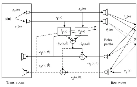
Fig. 1. Stereophonic acoustic echo cancellation system.
In a stereophonic acoustic echo cancellation system shown in Fig. 1,s(n)is the source ofx1(n)andx2(n)signals in the
transmission room. We havexi(n) =gi(n)∗s(n), wheregi(n) is the impulse response between the source and microphone in the transmission room. We define the echo signals in the receiving room as
yj(n, θ) =
2
X
i=1
θTxi(n) +vj(n), j= 1,2, (1) and the impulse response vector at time nby
θ= [θij,0(n), θij,1(n), ..., θij,L−1(n)]T (2)
is the echo path (length L) of the receiving room between loudspeaker iand microphone j and(·)T is the transpose.
is the far-end speech (loudspeaker) and vj is the near-end speech added at microphone j in the receiving room. We assume that vj is uncorrelated with xi(n). The estimated response based on the least-squares fitθˆcan be defined by
ˆ
yj(n,θˆ) =
2
X
i=1
ˆ
θTxi(n), (4) and the adaptive filter vector at timenby
ˆ
θ= [ˆθij,0(n),θˆij,1(n), ...,θˆij,Nj−1(n)]
T. (5)
Nj is the length of the adaptive filter when we estimate the errorej(n). The error signal for the estimation is defined by
ej(n) =yj(n,θ)−yˆj(n,θˆ) +vj(n). (6) From (6), we can see that once the synthesized echoyˆj(n,ˆθ) is equal to the echoyj(n,θ), the echo is completely cancelled and the signal transmitted to the transmission room is the near-end speech vj(n) only. This is the goal of the echo cancellation. An adaptive filter is used to identify the echo paths of the receiving room. The output of the adaptive filter, which is an estimate of the echo signal, can be used to cancel the undesirable echo. The estimated coefficients are chosen through an adaptive filter algorithm such that the cost function
J(ej(n))is minimized. The estimation errors are labelled with two subscripts. The first subscript denotes the filter lengthNj and the second subscript indicates the lengthLof the observed data [10]. We note that when the filter length Nj increases, the error decreases and vice versa. However, if the filter length increases, the adaptive filter algorithm becomes a rather expensive algorithm because its computational complexity grows in proportion to the check of the filter.
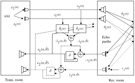
III. THE ERROR ESTIMATE ALGORITHM FORSAEC
Conventional filtering schemes estimate the parameter vec-torθ so as to minimize a cost function J(ej(n))of the esti-mation errorej(n). The cost function is usually chosen to be a squared error measureJ(ej(n)) = 1/2E[ej(n)2]. The optimal
ˆ
θ parameters are found by solving ∇ˆθE[ej(n)2] = 0in [10]. In this section, we propose the new algorithm, achieving a specified bound δ on the magnitude of the estimation error
ej(n)over a model space of interest. Any parameter estimate that results in the error being less than the specified bound
δ (Fig. 2) is an acceptable solution. When the bound on the error is properly chosen [11]–[13], we have
|ej(n)| ≤δ, (xi(n), yj(n,θ))∈Ω. (7)
Ω is the model space comprising input vector-desired output pairs over which we wish to impose the bounded error criterion. From (1-6), We have
y1(n, θ1) =x1(n)θT11+x2(n)θT12, (8)
y2(n, θ2) =x1(n)θT21+x2(n)θT22, (9)
with the transfer functions of the receiving room is
θ= [θ1, θ2]T = [θ11,L, θ12,L, θ21,L, θ22,L]T. (10)
The adaptive filter is used to identify an unknown system (the loudspeaker-to-microphone transfer function in receiving room)
ˆ
y1(n,θˆ1) =x1(n)ˆθ11T +x2(n)ˆθT12, (11)
ˆ
y2(n,θˆ2) =x1(n)ˆθ21T +x2(n)ˆθT22, (12)
with the adaptive filter coefficients is ˆ
θ= [ˆθ1,θˆ2]T = [ˆθ11,Nj,θˆ12,Nj,θˆ21,Nj,θˆ22,Nj]
T. (13) In Fig. 2, the error will be fedback and compared withδuntil
s(n)
( ) 2 g n
( ) 1 g n
( ) 2n
T
( ) 1n
T
( ) 1 x n
( ) 2 x n
ˆ ( )1n
T Tˆ ( )2n
ˆ ˆ ( , )2 y nT
Trans. room Rec. room
ˆ ( , ) 1
e nT
G ˆ ˆ ( , )1 y nT
G
( , ) 1 y nT
ˆ ( , ) 2
e nT
( , ) 2 y nT
Echo parths
( ) vjn
Fig. 2. Stereophonic acoustic echo cancellation control error system .
|ej(n)| ≤δ. We compare the new algorithm (EEA) with the set-membership normalized least mean-squares (SM-NLMS) algorithm [12].
Algorithm 1: The set-membership normalized least
mean-squares (SM-NLMS)
Set-membership identification (SMI) theory is a well-established paradigm in the area of system identification that exploits the assumption of a bounded noise process added to a linear-in-parameter model. The set-membership normalized least mean-squares (SM-NLMS) algorithm was presented in [12]. The set-membership filtering criterion is to find θˆ that satisfies
|ej(n)|2≤δ2, (xi(n), yj(n,θ))∈Ω. (14) We have
ˆ
θ(n+ 1) = ˆθ(n) +µej(n)xi(n) xT
i(n)xi(n)
, i= 1,2, (15)
µ= ½
1− δ
|ej(n)| if |ej(n)|> δ,
0 otherwise. (16)
Algorithm 2: The error estimate algorithm
From the SM-NLMS algorithm and affine projection (AP) algorithm, we propose the error estimate algorithm to optimize the filter length, as following
ej(n) =yj(n,θ)−yˆj(n,ˆθ), (17)
ˆ
[image:2.595.313.547.200.343.2]µ=P(n+ 1) = ·
P(n)−P(n)xi(n)x
T
i (n)P(n)
1 +xT
i(n)P(n)xi(n)
¸
, (19) whereµis defined from AP algorithm [9].
LetNj= 5 be the start length, the length of adaptive filter is computed by
Nj =
½
Nj+ 1 if |ej(n)|> δ,
Nj if |ej(n)| ≤δ, (20)
N=max(Nj). (21) When the algorithm is to converge, we have the simulation results in Table. I. In the error estimate algorithm, when the minimum error signal is fixed, we compute the filter lengths so that the error signal may approximate the minimum error signal δ. When the echo paths change, the adaptive filter automatically adjusts the filter lengths to the optimum values. The optimum value of the filter lengths is the N in (21). It is the necessary minimum value for the minimum error signal.
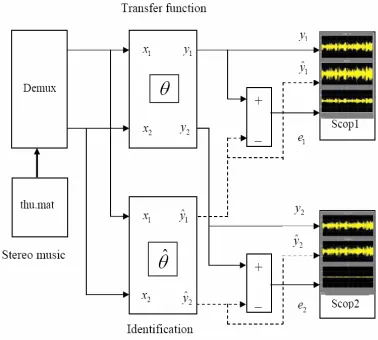
[image:3.595.308.552.84.513.2]IV. SIMULATION RESULTS
Fig. 3. SAEC control error simulation .
The structure shown in Figure 3 is the echo canceller simulation system. Using Matlab and Simulink software, we have the function blocks as:
- Stereo music block: read time and output values from the first matrix in the specified MAT file. In this block,thu.mat
file is made from thu.wav file with Tsam sample time,
Tsam= F1s = 8Khz1 . In this paper, we used the stereo music file because stereo music frequency is higher than talk signal frequency. And the stereo music identification is more difficult than the talk signal identification.
- Demux block: split thu.mat file into two vector x1(n) and
x2(n).
- Transfer function block: The top two panels of Figure 4 shown the loudspeaker signals,x1(n)andx2(n). The bottom
two panels show the echo signals,y1(n)andy2(n). Equations
(8) and (9) show the relationship between x1(n), x2(n)and
y1(n),y2(n). Using the transfer function matrix in [14]
G(x) = "
0.1x−8−0.3x−9
1+0.2x−1−0.2x−2 0.01x
−6−0.03x−7
1+0.02x−1−0.01x−2
−0.02x−7−0.02x−8
1+0.01x−1−0.01x−2 −0.2x
−8−0.3x−9
1+0.1x−1−0.2x−2
#
, (22)
we have
θ11=
N11
D11
, θ12=
N12
D12
,
θ21= N21
D21, θ22=
N22
D22, (23)
N11= [0.1,−0.3],
D11= [1,0.2,−0.2,0,0,0,0,0,0,0],
N12= [0.01,−0.03],
D12= [1,0.02,0.01,0,0,0,0,0],
N21= [−0.02,−0.02],
D21= [1,0.01,−0.01,0,0,0,0,0,0],
N22= [−0.2,−0.3],
D22= [1,0.1,−0.2,0,0,0,0,0,0,0].
0 2000 4000 6000 8000 10000 12000
−5 0 5
0 2000 4000 6000 8000 10000 12000
−5 0 5
0 2000 4000 6000 8000 10000 12000
−2 0 2
0 2000 4000 6000 8000 10000 12000
−2 0 2
x
1
x2
y
1
y
[image:3.595.96.285.325.495.2]2
Fig. 4. x1,x2 input signals andy1,y2 output signals .
- Identification block: simulate the adaptive filter with the ˆ
θ parameters. Equations(11)and(12)show theyˆ1,yˆ2 output
signal. The Matlab programs compute the parameters θˆ and link these results with identification block.
- Scop block: The error signals between the echo signals and the identification signals are shown on thescope1andscope2 (Fig. 5).
In this simulation, vj(n) is assumed to be zero when there is the stereo signal activity at the far-end. We consider the following parameters:
• The error signals,
• The relationship betweenδ andNj,
• The echo return loss enhancement (ERLE),
A. The error signals
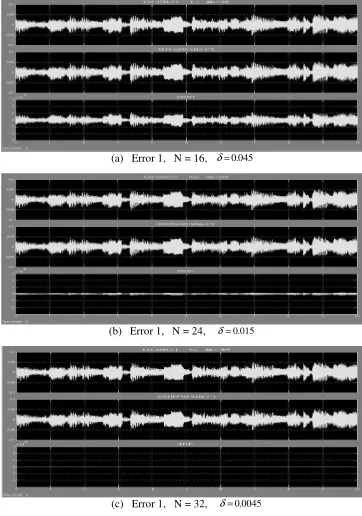
We can observe the y1, yˆ1 and e1 signals of the scopes
in Figure 3. In Figure 5, panel (a) show the error withδ = 45×10−3, when the filter length have the value N
1 = 16.
Withδ= 15×10−3 andδ= 4.5×10⁻³ , we have N
1= 24
andN1= 32in panels(b)and(c). When theδdecreases, the
filter length increases.
(a) Error 1, N = 16, δ=0.045
(b) Error 1, N = 24, δ=0.015
[image:4.595.75.256.155.413.2](c) Error 1, N = 32, δ=0.0045
Fig. 5. y1,yˆ1ande1 signals with N=16, 24, 32.
B. Relationship betweenδ andNj
Table I shows the simulation results for the relationship between the lengthNj of the adaptive filter and the bounded errorδ. When the bounded error decreases, the lengthNj of the adaptive filter will increase.Nj is the necessary minimum length of the adaptive filter. LetN1andN2be the result when
we use the EEA. When the bounded error criterion is chosen, the values ofN1 andN2 are different. In [1]–[6], the authors
defined the value ofNj to be the same. But in this paper, we show that they are different when we use the conditioning in (7). Therefore, when we design the adaptive filter, we must choose the length of adaptive filter equal to the maximum of
Nj.
C. The echo return loss enhancement (ERLE) LetPkn=1y2
j(n, θ)be the power of the echo signalyj(n, θ) at timen, andPkn=1e2
j(n)be the power of the residual-echo signal. TheERLE is defined as
ERLE= 10 log10 Pk
n=1y2(n)
Pk
n=1e2(n)
. (24) There are two important performance measures for echo cancellation: the convergence rate and the steady-state residual
TABLE I
THE BOUNDED ERRORS AND THE LENGTHS OF THE ADAPTIVE FILTER
The bounded error e1(n)< δ e2(n)< δ
δ N1 N2
10×10−3 25 45
7.0×10⁻³ 27 51
5.0×10⁻³ 31 58
3.0×10⁻³ 37 63
1.0×10⁻³ 52 74
0.7×10⁻³ 55 79
0.5×10⁻³ 57 82
0.3×10⁻³ 62 87
0.1×10⁻³ 77 98
echo. The steady-state residual echo equates the true echo subtracted by the synthesized echo after the algorithm is converged. We see that ERLE is a measure of how good an echo canceller is in terms of steady-state residual echo and convergence time. To see the results more clearly, in Figure 6, we have presented plots showing the echo return loss enhancement (ERLE) of the lengths of the adaptive filter (N = 16, N = 24, N = 32). The ERLE is lower for the case δ= 10×10−3 and higher for the caseδ= 0.1×10⁻³
than the ERLE compute with δ = 1×10⁻³. When the δ
decreases then the ERLE increases. This result confirms the high robustness of the EEA. We also compared the ERLE of
0 2000 4000 6000 8000 10000 12000 20
30 40 50 60 70 80 90
Time (sample)
ERLE (dB)
EEA with differents δ
[image:4.595.337.517.366.517.2]δ=10*10−3 δ=1*10−3 δ=0.1*10−3
Fig. 6. ERLE with N=45, N=74, N=98.
the EEA with the SM-NLMS algorithm. Figure 7 shows the ERLE of the proposed EEA and the SM-NLMS algorithm. The ERLE simulation results show that the EEA is better than the SM-NLMS algorithm.
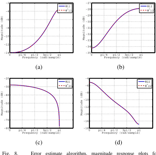
D. The convergence between θ andθˆ
The adaptive filtering algorithm for echo cancellation adapts the adaptive filter (ˆθ) by minimizing the error between the echo and the synthesized echo. Once the error is minimized, ˆ
θ is said to converge with the impulse respones θ. Figure 8 and 9 show the simulation results for the convergence of the adaptive filter with the EEA and the SM-NLMS algorithm. We set θˆ ≡ θ∗, δ = 0.01 (N = 25). In Figure 9(b, c),
we observe that θˆ12 is not to converge with θ12. They only
0 2000 4000 6000 8000 10000 12000 0
10 20 30 40 50 60 70
Time (sample)
ERLE (dB)
EEA (δ=0.01 ) and SM−NLMS (N=45)
EEA SM−NLMSA
Fig. 7. ERLE of the EEA and SM-NLMS algorithm.
0 pi/4 pi/2 3pi/2 pi
−14 −12 −10 −8 −6 −4 −2
Frequency (rad/sample)
Magnitude (dB)
θ11
θ* 11
(a)
0 pi/4 pi/2 3pi/2 pi
−35 −34 −33 −32 −31 −30 −29 −28 −27
Frequency (rad/sample)
Magnitude (dB)
θ12
θ* 12
(b)
0 pi/4 pi/2 3pi/2 pi
−80 −70 −60 −50 −40 −30 −20
Frequency (rad/sample)
Magnitude (dB)
θ21
θ* 21
(c)
0 pi/4 pi/2 3pi/2 pi
−18 −16 −14 −12 −10 −8 −6 −4
Frequency (rad/sample)
Magnitude (dB)
θ22
θ* 22
(d)
Fig. 8. Error estimate algorithm, magnitude response plots for: (a)θ11,θˆ11 (b)θ12,θˆ12 (c)θ12,θˆ12 (d)θ22,θˆ22.
V. CONCLUDINGREMARKS
Stereophonic acoustic echo cancellation with two acoustic paths becomes problematic since the two excitation signals are highly correlated. In this paper, we propose the EEA for SAEC and compare the ERLE of the EEA with the SM-NLMS algorithm. Simulation results show that the ERLE of EEA is higher than the ERLE of SM-NLMS algorithm. Our results show the convergence of the EEA is better than that of the SM-NLMS algorithm. The results in Table. I also show that the filter lengths are different. This result will help us to choose the optimal filter length. Although we only discussed the two-channel case here, the approach can be extended to the multi-channel case.
REFERENCES
[1] T. G¨ansler and J. Benesty. Stereophonic acoustic echo cancellation and two-channel adaptive filtering: an overview. International journal of adaptive control and Signal Processing, 14:565–586, 2000.
0 pi/4 pi/2 3pi/2 pi
−16 −14 −12 −10 −8 −6 −4 −2
Frequency (rad/sample)
Magnitude (dB)
θ11
θ* 11
(a)
0 pi/4 pi/2 3pi/2 pi
−36 −35 −34 −33 −32 −31 −30 −29 −28 −27 −26
Frequency (rad/sample)
Magnitude (dB)
θ12
θ* 12
(b)
0 pi/4 pi/2 3pi/2 pi
−80 −70 −60 −50 −40 −30 −20
Frequency (rad/sample)
Magnitude (dB)
θ21
θ*21
(c)
0 pi/4 pi/2 3pi/2 pi
−18 −16 −14 −12 −10 −8 −6 −4
Frequency (rad/sample)
Magnitude (dB)
θ22
θ*22
(d)
Fig. 9. Set-membership algorithm, magnitude response plots for: (a)θ11,θˆ11 (b)θ12,θˆ12 (c)θ12,θˆ12 (d)θ22,θˆ22.
[2] J. Benesty and T. Ga¨nsler. A multichannel acoustic echo canceler double-talk detector based on a normalized cross-correlation matrix. Acoustic echo and noise control, 13(2):95–101, Mar. 2002.
[3] T. G¨ansler and J. Benesty. A frequency-domain double-talk detector based on a normalized cross-correlation vector. Signal Processing, 81:1783–1787, 2001.
[4] P. Eneroth, S.L. Gay, T. G¨ansler, and J. Benesty. A real-time implemen-tation of a stereophonic acoustic echo canceler.IEEE Trans. on speech and audio processing, 9(5):513–523, July 2001.
[5] T. G¨ansler and J. Benesty. New insights into the stereophonic acoustic echo cancellation problem and an adaptive nonlinearity solution.IEEE Trans. on Speech and Audio Processing, 10(5):257–267, July 2002. [6] J. Benesty, T. G¨ansler, D. R. Morgan, M. M. Sondhi, and S. L. Gay.
Advances in Network and Acoustic echo cancellation. Springer-Verlag, Berlin, 2001.
[7] F. Lindstrom, C. Sch¨uldt, and I. Claesson. Efficient multichannel NLMS implementation for acoustic echo cancellation. EURASIP Journal on audio, speech and music processing, 2007(ID 78439).
[8] H. Choi and H-D Bae. Subband affine projection algorithm for acoustic echo cancellation system. EURASIP Journal on Advances in Signal Processing, 2007(Article ID 75621).
[9] A. Carini and G. L. Sicuranza. Filtered-x affine projection algorithms for active noise control using volterra filters.EURASIP Journal on Applied Signal Processing, 2004(12):1841–1848.
[10] B. Farhang-Boroujeny. Adaptive filters Theory and applications. John Wiley and Sons, 1998.
[11] I. Yamada, K. Slavakis, and K. Yamada. An efficient robust adaptive filtering algorithm based on parallel subgradient projection techniques. IEEE Trans. Signal Processing, 50(5):1091–1101, May 2002. [12] S. Gollamudi, S. Nagaraj, S. Kapoor, and Y-F Huang. Set-membership
filtering and a set-membership normalized LMS algorithm with an adaptive step size.IEEE Signal Processing Letters, 5(5):111–114, May 1998.
[image:5.595.75.253.55.201.2] [image:5.595.300.549.58.306.2] [image:5.595.37.286.237.485.2]