Faculty of Engineering and Surveying
The Development of a New Multi-Directional Fall arrest Device
A dissertation submitted by
Alan Grant Lance SILVA
In fulfillment of the requirements of
Courses ENG4111 and ENG4112 Research Project
towards the degree of
Bachelor of Engineering (Mechanical Engineering)
University of Southern Queensland
Faculty of Engineering and Surveying
Abstract
This research project has been undertaken to develop a mechanical solution that will automatically arrest the fall of a person working at height in any attitude while allowing unrestricted movement in normal use and to simplify the device set up.
Current fall arrest equipment used in industry are of a cumbersome design with limited application that can lead to potentially serious injury to the user.
Following a review of fall arrest systems used in industrial and recreational applications, a methodology for the design, prototype construction and testing procedures was
established.
This dissertation documents the process used to produce a working back up fall arrest device in the following areas:
- Conceptual design.
- Construction of a prototype. - Testing of the prototype.
- Evaluation of the design and testing.
Faculty of Engineering and Surveying
Limitations of Use
The Council of the University of Southern Queensland, its Faculty of Engineering and
Surveying, and the staff of the University of Southern Queensland, do not accept any
Responsibility for the truth, accuracy or completeness of material contained within or
Associated with this dissertation.
Persons using all or any part of this material do so at their own risk, and not at the risk
of the Council of the University of Southern Queensland, its Faculty of Engineering and
Surveying or the staff of the University of Southern Queensland.
This dissertation reports an educational exercise and has no purpose or validity beyond
this exercise. The sole purpose of the course pair entitled ‘Research Project’ is to
contribute to the overall education within the student’s chosen degree program. This
document, the associated hardware, software, drawings and other material set out in the
associated appendices should not be used for any other purpose: if they are used so, it is
entirely at the risk of the user.
Prof G Baker
Dean
Faculty of Engineering and Surveying
Certification
I certify that the ideas, designs and experimental work, results, analyses and Conclusions set out in this dissertation are entirely my own effort, except where Otherwise indicated and acknowledged.
I further certify that the work is original and has not been previously submitted for assessment in any other course or institution, except where specifically stated.
Alan Grant Lance SILVA
Student Number: 0039812125
________________________________________ Signature
17th October 2004
Acknowledgements
I would like to acknowledge the generous assistance, guidance and support given to me whilst undertaking the research project without which many of the tasks would have been difficult to achieve in the limited time I have had to complete the project.
Firstly to the research project supervisor,
Dr Selvan Pather
Of the University of Southern Queensland Engineering and Surveying Faculty,
for his valued guidance and suggestions throughout the whole period taken to complete the project.
Secondly,
Mr Boris Rogelja
Of Single Rope Technique Equipment, Padstow, New South Wales, for the generous use of his time, suggestions and use of his testing equipment to conduct the static testing on the prototype device.
Lastly,
My wife Christine and daughters, Tia Rana and Natasja Raine
• Abstract Page i
• Acknowledgements Page ii
• List of Drawings Page iii
• List of Figures Page iv
• List of Tables Page vii
• Glossary Page viii
• Chapter 1. Introduction Page 1
1.1.Introduction.
1.2. The Need for Research. 1.3. Dissertation Overview. 1.4. Project Objectives. 1.5. Chapter Conclusion.
• Chapter 2. Background Literature Review of Fall Arrest Methods Page 3 2.1. Introduction.
2.2. Government Legislation for Workplace and Recreation Fall Prevention. 2.3. Workplace fall related accident statistics.
2.4. Recreation Fall Related Accident Statistics.
2.5. Australia/New Zealand Standards for Workplace Fall Arrest Methods. 2.6. International Standards for Recreational Fall Arrest Methods.
2.7. Fall Prevention Measures Used in the Workplace. 2.8. Fall Prevention Methods Used in Recreational Areas. 2.9. Chapter Conclusion.
• Chapter 3. Current Type 1 Fall Arrest Fall Arrest Device Evaluation Page 23 3.1. Introduction.
3.2. Current Fall Arrest Models Selected for A Critical Evaluation. 3.3. Issues Identified From the Critique Evaluation.
3.4. Chapter Conclusion.
• Chapter 4. Design Criteria for the Research Project Back Up Fall Arrest Device Page 24 4.1. Introduction.
4.2. Design Considerations. 4.3. Chapter Conclusion.
• Chapter 5. Prototype Design and Manufacture Page 41
5.1. Introduction. 5.2. Material Selection.
5.3. Hand Stress Analysis Calculations for Key Prototype Components. 5.4. SOLIDworks Prototype Modeling of a Fall Arrest Prototype. 5.5. Finite Element Stress Analysis of Prototype Design Components. 5.6. Manufacturing the Prototype Components.
6.2. Types of Verification Testing Processes for the Back Up Rope Grab Fall Arrest Device. 6.3. Results of Testing.
6.4. Analysis of the Testing Completed to Date and Feedback for the Design Process. 6.5. Chapter Conclusion.
•
Chapter 7. Conclusion
Page 59
7.1. Introduction.
7.2. The Research Project Objectives. 7.3. Achieving the Objectives.
7.4. Deficient Areas of the Back Up Fall Arrest Device. 7.5. Further Work for the Back Up Fall Arrest Device Concept
• List of References Page R.1
• Appendices
Appendix A: Project Specification Page A.1
Appendix B: Current Fall arrest Devices - An Evaluation Critique Page B.1
Appendix C: Singapore Police Report Page C.1
Appendix D: Fall Hazards, Risk Assessment and Practical Methods for Page D.1 Eliminating/ Prevention – An Overview
D.1. Fall Hazard Risk Assessment.
Appendix E: ‘Back of the Envelope’ Stress Calculations For the Page E.1 Prototype Design
E.1. Analysis Information.
E.2. Forces On Blocking Cam and Guide Pulley Shafts. E.3. Minimum Cam Shaft Size.
E.4. Minimum Guide Pullet Shaft Size. E.5. Forces on Trigger Link Shafts E.6. Forces On Clutch Pulley Shaft E.7. Overall Shaft Design Factor
E.8. Bearing Stress/Loads at Clutch Frame and Hinge Frame Shaft Holes
E.9. Trigger Link Stress Analysis
Appendix F: Finite Element Analysis of Back Up Fall Arrest Page F.1 Prototype Design
F.1. Initial Design Cam Shaft Analysis F.2. Finial Design Cam Shaft Analysis F.3. Trigger Link Analysis
F.4. Hinge Frame Analysis
Appendix G: Clutch and Trigger Concepts for Back-Up Fall Arrest Page G.1 Device Prototype Design
G.1. Mechanical Concept Analysis for a Back-Up Fall Arrest Device
G.2. Fall Arrest Mechanics for a Centrifugal Brake Mechanism G.3. Fall Arrest Mechanics for a Back Up Fall Arrest Prototype
Design
List of Drawings
Appendix H
Drawing: SOLIDworks Model Back Up Fall Arrest Device Assembly Page H4
Drawing: SOLIDworks Model Back Up Fall Arrest Device Cam Left Hand Page H6
Drawing: SOLIDworks Model Back Up Fall Arrest Device Cam Right Hand Page H8
Drawing: SOLIDworks Model Back Up Fall Arrest Device Cam Shaft Page H10
Drawing: SOLIDworks Model Back Up Fall Arrest Device Centering Pin Page H12
Drawing: SOLIDworks Model Back Up Fall Arrest Device Clutch Spring Page H14
Drawing: SOLIDworks Model Back Up Fall Arrest Device Clutch Frame Page H16
Drawing: SOLIDworks Model Back Up Fall Arrest Device Clutch Pulley Page H18
Drawing: SOLIDworks Model Back Up Fall Arrest Device Clutch Pulley Bush Page H20
Drawing: SOLIDworks Model Back Up Fall Arrest Device Clutch Roller Page H22
Drawing: SOLIDworks Model Back Up Fall Arrest Device Clutch Shaft Page H24
Drawing: SOLIDworks Model Back Up Fall Arrest Device Guide Pulley Page H26
Drawing: SOLIDworks Model Back Up Fall Arrest Device Guide Pulley Bush Page H28 Drawing: SOLIDworks Model Back Up Fall Arrest Device Guide Pulley Shaft Page H30
Drawing:SOLIDworks Model Back Up Fall Arrest Device Hinge Frame Page H32
Drawing: SOLIDworks Model Back Up Fall Arrest Device Handle Page H34
Drawing: SOLIDworks Model Back Up Fall Arrest Device Handle Set Screw Page H36
Drawing: SOLIDworks Model Back Up Fall Arrest Device Latch Pin Page H38
Drawing: SOLIDworks Model Back Up Fall Arrest Device Clutch Actuating Ring Page H40 Drawing: SOLIDworks Model Back Up Fall Arrest Device Trigger Set Screw Page H42
Drawing: SOLIDworks Model Back Up Fall Arrest Device Trigger Catch Page H44
Drawing: SOLIDworks Model Back Up Fall Arrest Device Trigger Link Page H46
List of Figures
Chapter 2.
Figure 2.1. Fixed Working Platforms. Page 10 Figure 2.2. Work Positioning System. Page 13 Figure 2.3. (a). Industrial Rope Access Descent. Page 15 Figure 2.3. (b). Industrial Rope Access Ascent. Page 15 Figure 2.4. Abseiling Descent. Page 16 Figure 2.5. Bottom Belay Braking. Page 17 Figure 2.6. Frog Method of Ascender Rope Grab Attachment. Page 17 Figure 2.7. Dynamic Rope Belay of a Caver Climbing a Caving Ladder. Page 18 Figure 2.8. Rockclimbing Fall Arresting. Page 19 Figure 2.9. (a). The Most Severe Fall. Page 19 Figure 2.9. (b). Less Severe Fall. Page 19 Figure 2.10. Top Rope Belay. Page 20 Figure 2.11. Solo Back Roped Rock Climb. Page 21 Figure 2.12. Method of Roping up for Glacier Travel. Page 21
Chapter 3.
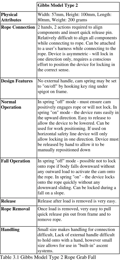
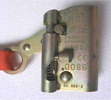
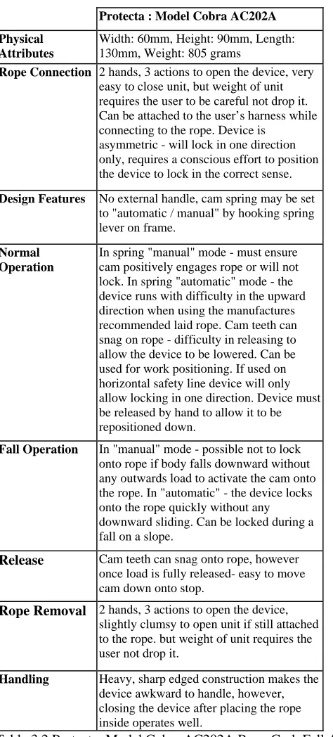
Figure 3.1. Gibbs Ascender Model “Type 2” Rope Grab. Page 23 Figure 3.2. (a). Aligning the Components. Page 24 Figure 3.2. (b). Inserting the Quick Release Pin. Page 24 Figure 3.3. The Protector “Cobra” Model AC202A Rope Grab. Page 25 Figure 3.4. (a). Two Distinct Hand Actions Used to Unlock the “Cobra”. Page 26 Figure 3.4. (b). Frame is Hinged Open to Accept the Safety Rope. Page 26 Figure 3.5. Petzl “Ascension” Right Handed Rope Grab. Page 27 Figure 3.6. (a). Open Cam and Lock Stop on Frame Using Thumb Page 29
Figure 3.6. (b). Place Rope in Frame. Page 29
Figure 3.6. (c). Release Stop to Secure Cam Against Rope. Page 29 Figure 3.7. Wren Industries “Silent Partner”. Page 31
Figure 3.8. (a). Connecting the Safety Rope. Page 31
Figure 3.8. (b). The Clove Hitch is Placed Around the Drum. Page 31
Chapter 4.
Figure 4.1. Wren Industries Silent Partner. Page 37 Figure 4.2. Proposed Clutch Mechanism. Page 37
Figure 4.3. Cardboard and Polystyrene Modeling of a Rotating Frame Idea. Page 39 Figure 4.4. The SOLIDworks Virtual Model of the Initial Design Idea. Page 40
Chapter 5.
Figure 5.1. SOLIDworks Final Prototype Assembly Model of the Back Up Fall Arrest Device. Page 42 Figure 5.2. SOLIDworks Exploded view of the Back up Fall Arrest Device Assembly. Page 43 Figure 5.3. Hinge Frame in Closed and Latched Position. Page 44 Figure 5.4. The Back Up Fall Arrest Prototype Design. Page 47 Figure 5.5. Initial Assembly of Back Up Fall Arrest Prototype Device. Page 48 Figure 5.6. The Initial Blocking Cam Units Found to be too Small. Page 48 Figure 5.7. The Initial Trigger Release Mechanism That Was Resized. Page 49 Figure 5.8. Clutch Pulley and Actuating Ring. Page 49
Chapter 6.
Appendix E
Figure E.1. Sketch of Back Up Fall Arrest Device In Orientated Fall Arrested Position Page E1
Figure E.2. Sketch of Blocking Cam and Guide Pulley Loads Page E2
Figure E.3. Sketch of Free Body Diagram for Blocking Cam and Guide Pulley Loads Page E2
Figure E.4. (a) Sketch of Cam Shaft Loads Page E3
Figure E.4 (b) Sketch of FBD for Cam Shaft Loads Page E3
Figure E.5. (a) Sketch of Trigger Link Shaft Loads Page E4
Figure E.5. (b) Sketch of FBD for Trigger Link Shaft Loads Page E4
Figure E.6 Sketch of Clutch Shaft Loading Based on Rope Path Centre Line Page E5
Figure E.7. Sketch of FBD for Clutch Shaft Loading Page E5
Figure E.8. Sketch of Shaft Groove Nomenclature for Grooved Shaft Bending Page E6 Figure E.9. Sketch of Shaft Cam Shaft Under Blocking Cam Distributed Load Page E7
Figure E.10. (a) Shear Force Diagram for Blocking Cam Shaft Page E8
Figure E.10. (b) Bending Moment Diagram for Blocking Cam Shaft Page E8
Figure E.11. Bearing Stress for Clutch and Hinge Frames at Shaft Holes Page E9
Figure E.12. Trigger Link Section Sketch Page E10
Figure E.13. Trigger Link Section A-A Sketch Page E11
Figure E.14. Trigger Link Section B-B Sketch Page E11
Figure E.15. Vector Force Diagram at Section B-B Page E12
Appendix F
Figure F.1 Constraints and Distributed Load Applied to Simplified Initial Cam Shaft ANSYS Page F1 Model
Figure F.2 Initial Cam Shaft ANSYS Solution Page F2
Figure F.3 Constraints and Distributed Load Applied to Simplified Final Cam Shaft ANSYS Page F3 Model
Figure F.4 Final Cam Shaft ANSYS Solution Page F3
Figure F.5 Constraints and Distributed Load Applied to Simplified Trigger Link ANSYS Model Page F4
Figure F.6 Final Trigger Link ANSYS Solution Page F5
Figure F.7 COSMOSxpress Trigger Link Plot showing the von Mises stress levels Page F6 Figure F.8 Constraints and Distributed Load Applied to Simplified Hinge Frame ANSYS Page F7 Model
Figure F.9 Final Hinge Frame ANSYS Solution Page F7
Figure F.10 COSMOSxpress Hinge Frame Plot showing the von Mises stress levels Page F8
Appendix G
Figure G.1 Clutch Mechanism Nomenclature Page G2
Figure G.2 (a) FBD of Forces on Upper Roller Page G2
Figure G.2 (b) FBD of Forces on Lower Roller Page G2
Figure G.3 Final Design Layout of Clutch Mechanism Page G3
Figure G.4 Vector Forces Generated by Rope Sliding Over the Locked Clutch Pulley Page G4 Figure G.5 Fall Forces Generated by Unlocked Falling Fall Arrest Device and Locked Fall Page G4 Arrest Device
Appendix H
Figure H.1 Drawing Construction of an Epicycloid Page H1
Figure H.11 SOLIDworks Model Back Up Fall Arrest Device Prototype Clutch Pulley Bush Page H19 Figure H.12 SOLIDworks Model Back Up Fall Arrest Device Prototype Clutch Roller Page H21 Figure H.13 SOLIDworks Model Back Up Fall Arrest Device Prototype Clutch Shaft Page H23 Figure H.14 SOLIDworks Model Back Up Fall Arrest Device Prototype Guide Pulley Page H25 Figure H.15 SOLIDworks Model Back Up Fall Arrest Device Prototype Guide Pulley Bush Page H27 Figure H.16 SOLIDworks Model Back Up Fall Arrest Device Prototype Guide Pulley Shaft Page H29 Figure H.17 SOLIDworks Model Back Up Fall Arrest Device Prototype Hinge Frame Page H31 Figure H.18 SOLIDworks Model Back Up Fall Arrest Device Prototype Handle Page H33 Figure H.19 SOLIDworks Model Back Up Fall Arrest Device Prototype Handle Set Screw Page H35 Figure H.20 SOLIDworks Model Back Up Fall Arrest Device Prototype Latch Pin Page H37 Figure H.21 SOLIDworks Model Back Up Fall Arrest Device Prototype Clutch Actuating Page H39 Ring
Figure H.22 SOLIDworks Model Back Up Fall Arrest Device Prototype Trigger Adjustment Page H41 Set Screw
List of Tables
Chapter 3.Table 3.1 Gibbs Model Type 2 Rope Grab Fall Arrest Device Evaluation. Page 25
Table 3.2 Protecta: Model Cobra AC202A Rope Grab Fall Arrest Device Evaluation. Page 27 Table 3.3 Petzl Model Ascension Rope Grab Fall Arrest Device Evaluation. Page 30 Table 3.4 Wren Industries Model: Silent Partner Rope Grab Fall Arrest Device Evaluation. Page 32
Chapter 5.
Table 5.1. Purchase Costs of Prototype Materials May 2004. Page 41
Table 5.2. Material Properties for Selected Materials Used in Prototype Manufacturing. Page 42
Table 5.3 Component Manufacturing Quantity and Production Time. Page 50
Chapter 6.
Table 6.1. Test Report for Back Up Fall Arrest Blocking Cam Verification 9th August 2004 Page 56 Table 6. 2. Test Report for Back Up Fall Arrest Blocking Cam Verification 12th August 2004 Page 56 Table 6.3. Test Report for Back Up Fall Arrest Blocking Clutch and Cam Mechanism
Maximum Fall Distance Check 13th August 2004 Page 57
Appendix B.
Glossary of Terms
Abseiling:
Controlled method of descending a fixed rope.
Belay:
Method used by recreational climbers to protect a lead/seconding climber and limit a free fall.
Descender:
Mechanical device attached to single or double rope to allow a person to abseil at a controlled rate and in a controlled manner.
Dynamic Rope:
High elongation synthetic fibre rope used by climbers to reduce deceleration forces imposed on a falling climber sustained by a sudden arrest, generally in 50metre lengths of 8.8 to 11mm diameter with up to 18% elongation under load.
Energy Absorber:
Device designed to reduce the deceleration force imposed by a sudden arrest to less than 6kN of force.
Harness:
Synthetic fabric webbing fabricated to be worn by a user to allow connection to safety point/descender/ascender
Jumar:
Generic name now given to hand held mechanical rope ascent device. Originally designed and manufactured by the Swiss Walter Marte in 1958. Variation still in current production
Karabiner:
Metal ring with a spring loaded close gate used for attaching equipment together - capable of being opened /closed, locked by hand and able to be loaded to 24kN in the primary axis.
Limited Free Fall:
A free fall not greater than 600mm.
Lanyard:
A line used to connect a fall – arrest harness to a safety point/line.
Protection:
Method by climbers used to provide rapid/portable anchor points
Prussiking:
Controlled method of ascending a single fixed rope using two or more mechanical ascender devices in an alternate progressive motion.
Rope Grab:
Safety Line:
A synthetic fibre rope used as a back up to arrest a limited free fall in the failure of the working line.
Static Rope:
Low elongation synthetic rope used for working and safety lines in industrial applications. Rope lengths can be up to 100 metres of 9 to 13mm with elongation of less than 5%. Kernmantle construction with abrasion resistant outer sheath, Australian/New Zealand Standard 4142.3 refers. An energy absorber must be incorporated if used as a safety line.
Working Line:
A synthetic fibre rope use for the primary support in industrial applications including ascent and descent of an operator.
Type 1 Fall Arrest Device:
Classification under Australian/New Zealand Standard 1891 pertaining
to a fall arrest device that can travel along an anchorage line, locks to the line when loaded and can only be loaded in the direction of the line.
Type 2 Fall Arrest Device:
Classification under Australian/New Zealand Standard 1891 pertaining
to a fall arrest device that contains a spring retracted anchorage line that pays out, the mechanism locks when loaded and retracts when the load is released.
Type 3 Fall arrest Device
Classification under Australian/New Zealand Standard 1891 pertaining
to a fall arrest device that contains a spring retracted anchorage line that pays out, the
1.1.
Introduction.
1.2. The Need for Research.
1.3. Dissertation Overview.
1.4. Project Objectives.
Chapter 1. Introduction
1.1.
Introduction
While the contrasts of working at heights and enjoying a height related outdoor activity might seem so different the way fall prevention is approached, eliminating or minimizing the potential for death or serious injury from a fall is paramount in both areas.
In Australia, falls from heights that cause serious injuries or death in many industry sectors are estimated to contribute to over 20% of all workplace fatalities annually.
Falls can occur in almost every workplace environment or on any height related outdoor activity where there is a potential fall hazard, the contributing factor of height can magnify the severity of injuries sustained in fall.
Several fall prevent methods are used in both workplace and recreation areas where the risk of a fall is present. The methods include preventative and pro-active measures to eliminate the risk of a fall or to minimize the fall distance to an acceptable level of risk to a person.
1.2.
The Need for Research
Current fall prevention methods used in the workplace are cumbersome and of limited in application that can hinder their operating effectiveness in the advent of a fall. These deficiencies can potentially lead to serious injury or death to the user if the equipment is incorrectly set up or fails during a fall.
Equipment used for recreation is generally both well designed and adaptable for use in many different areas of application. While the equipment is generally designed for lower margins of safety in order to reduce weight and manufacturing costs, the equipment is sufficiently strong enough to withstand the fall forces generated in the advent of a fall.
Research into workplace and recreational fall prevention methods may identify limitations and positive features that could lead to improvements in design and application to eliminate these deficiencies, making the devices safer for the equipment user.
1.3.
Dissertation Overview
This dissertation has used a methodology of:
• Design conceptualization was formulated using a review of:
• State Government Occupational Health and Safety legislation pertaining to work related fall prevention methods.
• Workplace and recreational fall related accident statistics.
• Workplace and recreational fall prevention methods.
• Australia/New Zealand and European Standards required for fall arrest systems and equipment.
• Critical evaluation of several current fall arrest devices.
• Prototype modeling
• Device testing criteria using the Australia/New Zealand Standards and a test proposal for evaluating components outside of the Australia/New Zealand Standards
• Evaluation of prototype test results
• A review of prototype test results
1.4.
Project Objectives
To establish the design concepts for the Research Project, the review of background literature and evaluation of several current fall arrest devices identifiedfour key objectives to be met:
• Simplify device connection to the safety rope.
• To design a device that is intuitive to use and eliminate incorrect safety rope attachment.
• Operate without any user inputs.
• Adaptable for several different fall arrest methods.
1.5.
Chapter Conclusion
The Introduction Chapter has identified the key areas that have been explored and developed in this dissertation to produce a tested working prototype model based on the dissertation overview to satisfy the project objectives.
Methods
2.1. Introduction.
2.2. Government Legislation for Workplace and Recreation Fall Prevention.
2.3. Workplace fall related accident statistics.
2.4. Recreation Fall Related Accident Statistics.
2.5. Australia/New Zealand Standards for Workplace Fall Arrest Methods.
2.6. International Standards for Recreational Fall Arrest Methods.
2.7. Fall Prevention Measures Used in the Workplace.
2.8. Fall Prevention Methods Used in Recreational Areas.
Chapter 2. Background Literature Review of Fall Arrest
Methods
2.1. Introduction
This chapter explores areas of fall arrest method literature identified in Chapter 1 to establish a basis for the design criteria that has been used for the research project. These specific areas reviewed for the fall arrest methods include:
• Government Occupational Health and Safety legislation for workplace and recreation fall arrest prevention.
• Workplace fall related accident statistics.
• Recreation fall related accident statistics.
• Australia/New Zealand and international standards for fall arrest methods and equipment.
• Fall prevention Methods used in the workplace.
• Fall prevention Methods used in recreation activities.
An overview of Risk Assessments for Fall Hazards identified in the literature review of Occupational Health and Safety legislation for the workplace can be viewed in Appendix D.
Background Literature Review
2.2. Government Legislation for Workplace and Recreation Fall Prevention
• Occupational Health and Safety Act And Regulations For Workplace Fall Prevention.
An increase in the number of fatal accidents and severity of injuries sustained from fall related workplace accidents has meant that all Australian state governments have had to impose legislative controls to prevent workplace falls.
Each Australian state and territory has enacted Occupational Health and Safety Act legislation (OH & S Act) to provide a framework of Occupational Health and Safety Regulations (OH & S Regulations) for identifying, eliminating or controlling work related risks. This is accomplished by implementing mandatory risk control measures in the areas of lighting, noise, atmosphere, electricity, confined spaces, heights and man-handling. (New South Wales Occupational Health and Safety Regulation Chapter 4 2001).
The stated objective of the Victorian State Governments Occupational Health and Safety Regulation 2003 legislation is:
“To eliminate accidents at a workplace involving falls – specifically falls from over 2 metres or to reduce the potential for injuries from a fall”
• Industry Codes of Practice For Specific Workplace Areas
Industry “Codes of Practice” have been adopted to provide practical advice for implementing the regulatory requirements. The NSW WorkCover Authority Code of Practice Safe Work on Roofs, Part 1 – Commercial and Industrial Buildings says:
“The codes of practice have been developed by a tri-partite working party and has involved extensive consultation with industry and other special interest groups”
choose to comply with the regulations in another way that fulfils the requirements. The codes of practice have been drafted for specific types of workplace environments by use of a “check list” approach to ensure work is done safely by conducting a risk assessment, work system preparation check and then to implement the control measures that will prevent falls during the work process. Specific topics covered by the codes describe the work areas where the codes are to be used, preferred methods to be considered for fall prevention, other control methods with their inherent risks, personal protective equipment provisions, training and instruction, and legal requirements.
The codes have incorporated Australia/New Zealand Standards publications to be used as additional guidance for complying with the OH & S regulations. Australian/New Zealand Standards are prepared by a technical committee comprising state government statutory departments, employer bodies, unions and interested parties that specify requirements for selecting, using, maintaining and testing industrial fall prevention systems and devices. (Australia/New Zealand Standard AS/NZ 4488.2:1997 Industrial rope access systems)
• Recreational Activity Legislation For Fall Prevention
Private recreational height related activities are specifically excempted from each state OH &S legislative act but are covered under several state regulations for National Parks and Local Government acts that only seek to impose restrictions not to regulate such activities. (Victorian Occupational Health and Safety, Prevention of Falls Regulations p.5 2003).
2.3. Workplace fall related accident statistics
Each Australian state and territory has a regulatory authority body, WorkCover/ WorkSafe, that oversees and enforces each the OH & S legislative acts and regulations required for plant designers, plant manufacturers, employers and employees to be implemented for preventing accidents due to falls from height at the workplace. One function of the body is to collect accident reports for statistical analysis of accident trends across industry groups to provide feed back of regulatory effectiveness.
The bodies provide yearly reports that present accurate information on accidents by type, severity, lost man-hours and cost to the community for overall and by industry groupings. Accident trends for previous years for comparisons are also reported.
• Over a three-year period, 23 people were killed in workplace falls in Victoria alone, while many more were seriously injured in falls. (Victorian WorkCover Authority WorkSafe Online viewed 5 March 2004).
• In New South Wales, for the nine-year period 1991/1992 to 2000/2001 78 people were killed in falls from heights at the work place.(WorkCover NSW Worker Compensation Statistical Bulletin Section 2 Table 2.3.1 2000/2001).
2.4. Recreation Fall Related Accident Statistics
Statistics related to recreation fall related accidents have been collated by recreational sporting bodies for use as an accident preventative measure in several countries around the world.
The Australian Climbing Accident Data operated by members of the Victorian Climbing Club has collected records of 300 climbing accidents for the fifty year period to 2004 of Australians undertaking recreational activities for the specific areas of abseiling,
rockclimbing, gymnasium climbing and mountaineering. The database provides an overview for accident type, severity, activity, age and experience of the participants and gives selected findings into several of the accidents.
The ACAD report, Climbing Accidents in Australia 1955-2004, reports that of the 83 deaths to Australians in climbing related activities in Australia and internationally, 40 people were killed in fall related accidents. The report’s author states that specific analysis of the statistics breakdown is yet to be conducted. However he provides selected findings that highlights the need for several preventative measures that could potentially reduce the severity of climbing related accidents. (Climbing Accidents in Australia 1955 –2004. Ian B Sedgman).
2.5. Australia/New Zealand Standards For Workplace Fall Arrest Methods
The Australia/New Zealand Standard AS/NZ 1891.4:200 Industrial fall-arrest systems and devices Part 4: Selection, use and maintenance 31 July 2000 recommends for:
• Total restraint – using a restraint belt and fixed restraint lanyard attached to an anchor of 6kN ultimate tensile strength.
• Restrained falls – either a body belt or work positioning harness should be used with a fixed length restraint lanyard of 6kN ultimate tensile strength.
• Limited free fall - a fixed lanyard and work positioning harness should be used with an anchorage of ultimate tensile strength 12kN or horizontal lifeline/rail system to limit a free fall of less than 600 mm.
• Free falls - the fall arrest system used with a fall arrest harness lanyard or fall arrest device connected to a 15kN ultimate strength anchor or horizontal lifeline/rail system should limit a free fall to 2 metres maximum.
Selection for determining the most appropriate types of system components for the envisaged use is based on:
• Risk assessment of hazard.
• Work type.
• Mobility requirements were the degree of lateral and vertical movement needed to perform a task while connected to system.
• System components should be compatible with each other to ensure maximum degree of safety, comfort, freedom of movement and security against injury in the advent of a fall. Potential and severity of the fall risk.
(Australia/New Zealand Standard AS/NZ 1891.4:200 Industrial fall-arrest systems and devices Part 4: Selection, use and maintenance 31 July 2000).
Safe use relating to practices to be followed for the selected system:
• Fall arrest equipment should be used in accordance with the manufacturer’s instructions.
• The equipment should be carefully handled to preclude damage. Defective equipment should be destroyed or marked “defective” to prevent it being reused.
• Particular fall arrest equipment should be used only if there is sufficient fall clearance for the system to operate.
• Rescue provisions are in place to quickly remove a person from a suspended position. The provisions should reflect an awareness that a person can only be suspended in a harness for a short time after sustaining a fall as they may suffer suspension trauma from blood pooling in their legs which can lead to loss of consciousness and eventually death.
• Inspection, maintenance and storage.
• All equipment items in regular use are subject to scheduled periodic inspection and servicing at either manufactures recommendation or the guidelines listed in the standard.
• Accurate equipment records for each piece of equipment should be kept for documenting the service and maintenance history.
• Equipment should be stored dry and away from excessive heat, humidity or moisture.
Equipment types used for Fall-arrest devices are described in Australia/New Zealand Standard AS/NZ 1891.3 Industrial fall-arrest systems and devices Part 3: Fall-arrest devices:
• Lanyards made of synthetic webbing may be required to make the connection between the workers harness and a safety anchor or back up rope grab. The lanyard length should be as short as practicable to prevent a free fall longer than 600 mm. A short lanyard of 300mm is recommended if a worker is to incorporate a personal energy absorber when a back up rope grab is used.
• Fall arrest devices may utilize grab cams or inertial elements to lock and arrest a worker in the advent of a fall.
Australia/New Zealand Standard AS/NZ 1891.3 Industrial fall-arrest systems and devices Part 3: Fall-arrest devices classifies the devices as;
“Type 2 – a fall-arrest device from which a spring loaded anchorage line pays out, and which locks when loaded and releases when the load is removed, e.g. an inertia-reel device”
“Type 3 – a fall arrest device from which a spring-loaded anchorage line pays out, which locks when loaded, but may be wound back as a winch after loading and locking.”
2.6. International Standards for Recreational Fall Arrest Methods
Standards for commercially available recreational equipment have mainly been European in origin, the two main standards in use are:
• Union Internationale de Association d’ Alpinisme (UIAA).
The first requirements for climbing ropes where adopted in 1951 by the UIAA over concerns with rope quality particularly with the then recently introduced nylon 66 ropes (UIAA website 2001).
The UIAA is an international representative body of international and national mountaineering and climbing bodies and guides associations from over 70 countries from around the world including Australia and New Zealand that actively promote mountain recreation.
The UIAA website’s official history says for mountaineering equipment:
“ (the) UIAA role is to promote reliable equipment suited to the needs of the terrain”
UIAA Safety Standards and quality control committees have been long established to ensure equipment manufactures that seek UIAA endorsement comply with the UIAA standards. The UIAA label is marked onto equipment that is recognized by these UIAA committees. Many of the UIAA standards for recreation equipment have been referred to for European Standards (EN) which have been produced to cover recreational equipment compliance for industrial applications in the 18 European Economic Area countries.
• CE Marking System
Many international manufactures of personal protective recreational equipment (PPRE) have begun adopting European Economic Area (EEA) conformance procedures and regulations that require them to comply with design and manufacturing requirements for their products. The CE Marking system has become a defacto standard for a majority of PPRE manufacturers around the world as all PPRE products that are intended to be sold in the European market are obliged to carry the CE marking before they can be freely traded in the 18 member countries of the EEA.
The CE Marking system indicates that the product conforms to set European health, safety and environmental protection legislation subject to conformity assessment procedures.
The CE Markingwebsite comments:
The benefit of implementing the CE marking requirements for the manufacturer has been of greater user acceptance now that the PPRE products are now designed and manufactured to a safer and consistent standard than previously.
However equipment and systems used in the workplace in EEA members countries are still required to conform to European Standards. (CE Marking Website 2001)
• From Recreational Use to Industry Standards:
The cross over from recreational to industrial use has been accomplished through the European and Australia/New Zealand Standards system of using technical committees to specify the standards requirements. In compiling several of the EN standards for a particular industrial fall arrest device the UIAA standard for the device has been used as a reference. Several of the Australian Standards for industrial fall arrest devices have in turn referred to the relevant EN standard for compiling the Australia/New Zealand standards requirements. (AS/NZ 1891 4:2000).
UIAA members: the New Zealand Alpine Club and the New Zealand Mountain Guides Association have had representation on the Joint Technical Committees that have formulated the standards requirements for certain Australia/New Zealand standards. This has led to increased awareness of risk assessment and alternate fall prevention techniques and has allowed scope for flexibility while reducing risk and overall cost of complying with the government regulations for working at heights. For specific Australia/New Zealand Standards, specific EN standards are accepted under the requirements of the Australian system. (AS/NZ 1891.3:1997 p.5) A number of recreational fall arrest items that are commercially available in Australia can in fact have several international standards labels; the UIAA label, a CE Mark, an EN number and an AS/NZ standards number. (Petzl Rescucender brochure 2001).
2.7. Fall Prevention Measures Used in the Workplace
Work-site control measures are developed using the risk assessment and the hierarchical system approach to rank the order of fall control measures required. Practicable measures for controlling fall risk are selected according to how appropriate they are in performing the task and the severity of the risk involved.
2.7.1 Work on Ground
By eliminating the requirement for a task to be performed at height, the risk due to a fall may be effectively nullified. Methods can include using prefabrication of components at ground level and erection on site or the use of tools with extended handles. (WorkCover Victoria Code of Practice – (No.28) – Prevention of Falls in General Construction p.8 31 March 2004).
2.7.2. Work from a Solid Surface
By utilizing areas of a work-site to act as a solid surface that can support people, equipment and material loads, the fall risk can be eliminated by:
• Ensuring that the surface is of sufficient structural strength that will safely carry the expected loads. A structural engineer may need to determine the safe load capacity.
• Providing perimeter protection around all exposed openings and edges from or through which a worker could fall.
• Providing a safe means of access and egress to the solid surface. Permanently fixed platforms are required to comply with Australia/New Zealand Standard AS/NZ 1657 Fixed platforms, walkways, stairways and ladders – Design construction and
installation
2.7.2 Passive Fall Prevention Measures
Passive fall measures are a combination of material and equipment designed and installed with the intention to prevent a worker falling that does not require any on going adjustment, alteration or operation by any person to ensure the integrity of the system to provide that function.
2.7.3.1 Temporary Work Platforms – Scaffolding
Scaffolding is used for many applications where a temporary stable and safe work platform is required for work at height. Depending on anticipated loads, scaffolding is rated as light, medium, heavy or special duty for the safe loading limitations. State government
regulations require that scaffolding where a person or object could fall more than 4 metres must be erected by certified rigger and the scaffolding must comply with Australia/New Zealand Standard AS/NZ 4576 Guidelines for scaffolding.
Scaffolding can introduce additional hazards and risks during erection and use:
• Falls from height during erection and use by ensuring full platform decks, handrails and access ladders are progressively installed.
• Use toe boards and platform trapdoors to prevent objects from falling.
• Surface conditions are vital for the strength and stability of the scaffolding.
• Weather conditions strong winds during erection.
(WorkCover Victoria Code of Practice – (No.28) – Prevention of Falls in General Construction pp. 9-11 31 March 2004)
2.7.3.2 Elevated Work Platforms
There are many types of elevated work platforms (EWP) available for use in industry to provide mechanized access for work at heights that provide a stable ground based level work platform. The platforms are considered plant and are subject to State plant regulations for design, installation, use and maintenance. Australia /New Zealand Standard AS/NZ 2550.10 Cranes - Safe use - Elevating work platformsrefers to specific measures for safe use:
• Safe working load limits should be clearly marked on the unit.
• Operators working above 11 metres in boom lifts, cherry pickers or travel towers are required to wear a safety harness anchored to a secure point in the work platform area that will arrest a fall from the work platform. All operators are required under state regulation to hold an EWP operator certificate to ensure competency.
• EWP should only be used on a solid level surface unless specifically designed for operation on rough terrain. The surface should be inspected for obstruction hazards that could cause the unit to overturn.
• Check weather condition – particularly high winds, which could overturn the EWP. EWP can be powered either by internal combustion engines or storage battery electric-hydraulic units that include;
(i) Scissor lift units available in wide selection of work platform areas and reach – generally self driveable, but are required to be stabilized before being operated at height, operation is generally restricted to vertical movement only.
operated throughout their full range of movement with out the need for
stabilization if used on a level surface. Required to be positioned and stabilized before operating the boom.
(iv) Travel platforms – these include mast/ tower climbing platforms and
horizontal travel platforms. Travel platforms may be of a portable design that can be towed into position and stabilized for use or are erected at the work-site for use.
2.7.3.3Fabricated Work Platforms
Fabricated work platforms (FWP) are designed for specific tasks that can be
permanently fixed, portable or mobile to provide a stable work area for work at height. FWP incorporate perimeter guard-railing, toe boards, barriers, safe access/ egress to the work platform, and safety anchor attach points complying to Australian/New Zealand Standard AS/NZ 1891 Industrial fall-arrest systems and device for platforms, for heights above 2m.
Portable/ mobile FWP are designed to form a permanent moveable “solid work surface” that can be positioned around a work-site for a specific task:
• Construction and building use for concrete column and ceiling fixture work.
• Aircraft maintenance access stairs for entry/ egress to aircraft or for fixed height work platforms used for aircraft servicing, some types incorporate hydraulic height adjustment. Docking systems used for aircraft maintenance work provide a multi-level “solid work surface” that are designed to provide safe access and eliminate fall hazards on fuselage, wings and empenage areas. Aircraft docking systems can be either roof suspended and/or floor mounted with levels linked by access stairways or ladders, Figure 1. Below shows how a combined floor mounted/roof suspended system is used to enclose a Boeing 747-400 aircraft. Several modules are used to encompass a whole aircraft. Ground mounted modules are towed/ pushed into position while roof suspended systems lower the dockings into position by electric motor or pneumatic driven jackscrews. Provisions are made for safety harness-attach points and lowerable perimeter guardrails for flight control operation checks and aircraft de-docking.
Figure 2.1. Fixed Working Platforms
[image:27.595.131.546.540.710.2]Dockings decks are designed to support operation loads for specific maintenance tasks and to allow limited re-configuration of the docking sections due to different aircraft or engine types. (Airlines Support Industries Australia Pty Ltd Brochure March 2004) Traverse /climbing platforms (T/CP) used for building maintenance.
T/CP types include cable climbing “window cleaner/ painter” platforms that are electric motor powered and purlin trolleys that traverse the length of a horizontal steel beam. For purlin trolleys roof structures are required to be capable of supporting the trolley and operational loads. The T/CP must be provided with holding brakes and mechanisms to prevent the platforms from inadvertent dislodgment from purlins. Fall protective guardrails on T/CP are required, if this is not practicable the user must wear a safety harness anchored to the platform.
To reduce hazards when using portable/ mobile FWP only use on level surfaces that can support the load safely. Lock the castors to prevent movement the FWP while anyone is on them.
2.7.3.4 Perimeter Protection Against Fall Hazards
Perimeter protection (PP) provides a high level of all of fall protection against a worker inadvertently falling from an unprotected edge or opening. State codes of practice recommend that PP provision be made if work is to be carried out within 2 metres of any edge where a person could fall 2 metres or more.
The NSW WorkCover Code of Practice Safe Work on Roofs Part 2 – Residential Buildings 1 March 1997 recommends that:
“perimeter protection should be provided for all work irrespective of height if the risk assessment has identified an increased risk of falling from
• slippery roofing materials
• the pitch of a roof exceeds 25 degrees, or 15 degrees if it made from a brittle material
• if a hazardous situation exists below the work surface onto which a person could fall if a worker is exposed to a risk of a 2 metre fall from a roof perimeter”
Methods of perimeter protection that are used are:
• Safety Meshing/ Netting. While not strictly part of PP, the mesh system is generally used in conjunction with edge and perimeter protection while
performing roof work. Meshing/ netting can either be long term where a wire mesh is placed under a brittle or fragile roof or as a temporary protection measure were a flexible net is placed over a brittle or fragile roof. The mesh/ net system works by preventing a worker from an internal fall if the worker breaks through a brittle or fragile roof surface or when installing roofing materials. For brittle and fragile roofs permanent safety meshing consists of 2 millimetre diameter steel wire welded into a mesh of 150 mm by 300mm spacing that is secured to roof purlins by a qualified contractor in accordance with Australian Standard 2424-1981 Plastic Building Sheets – General installation requirements and design of roofing systems. Safety netting is applied as a fall prevention measure by placing cables over each roof bay and the roof perimeter, then the net is hung over each cable and is then secured are secured in position. The CP93British Standard Institution (BSI) Code of Practice for the Use of Safety Nets on Construction Works refers to net installation for use in New South Wales.
cutting processes. Repairs are required to be carried out before work is resumed above the net.
• Exterior Perimeter Screens are used for building facades during construction or renovation work. Purpose built screens are either secured to the exterior of a building or secured to scaffolding that surrounds the building, screens are required to cover at least two levels of a work-site. The screens serve three main purposes by protecting people below the work-site from falling debris, to prevent workers from falling from the perimeter edge at the work site level and to provide fall protection while an upper level is being constructed.
(WorkCover Victoria Code of Practice – (No.28) – Prevention of Falls in General Construction pp. 23-24, 31 March 2004)
• Perimeter Guardrails provide effective fall prevention at perimeter edges,
skylights, on fragile roofs, openings in floor or roof areas, and at edges or shafts or excavated areas.
The NSW WorkCover Code of Practice Safe Work on Roofs, Part 1- Commercial and Industrial Buildings November 1993 recommends that guardrails should be between 900 mm and 1 metre in height above the work surface, to incorporate a mid rail, have a toe board if the slope of the roof exceeds 15 degrees and be constructed to withstand a force of 0.445 kN at any point on the rail.
The most appropriate type of guardrail system is dependent on the roof pitch angle, the roof structure that the guardrail will be attached to and the force applied by the momentum of a falling person.
For a steep roof of 38 and up to 45 degrees, the NSW WorkCover Code of Practice Safe Work on Roofs, Part 2 – Residential Buildings 1 March 1997 recommends that a two plank 450 mm wide working “catcher” platform with an outer guardrail be constructed out from the roof perimeter. This is to minimize the likelihood of a worker falling onto, then over the guardrail
2.7.3.5 Work Positioning Systems
Work positioning systems (WPS) allow a worker to be positioned and safely supported while performing a task at an elevated work-site. WPS are requires a higher level of training and competency with close supervision required to ensure correct procedures are adhered to.
The Victorian WorkSafe Code of Practice for the Prevention of Falls in General Construction 31 March 2004 states;
“ according to the hierarchy of control they (WPS) should only be used where it is not practicable to use higher order controls”
For steep work areas that exceed 35 degrees, guardrails and catcher platforms are considered inappropriate by the Victorian WorkCover as standing is made difficult on steep roofs or parts of an aircraft structure.
WPS using travel restraints, industrial rope access equipment or scaffold platforms/ roof pitch laddering systems should be used to provide a safer alternative.
• Travel Restraint Systems. Travel restraint systems (TRS) prevent workers from
permanent anchors and building or plant structure are suitable to support the anticipated loading, safe access and egress to the safety anchors/ static line points.
Careful consideration should be given for positioning the anchor points to limit a free fall and to prevent possible ‘swing down’ or ‘swing back’ falls where the worker is swung down onto a lower surface or back into an obstruction if the worker has been working at an angle away from the anchor. Damage to the lanyard can occur if the falling worker is allowed to swing back across a perimeter edge until directly below the anchor. To prevent this occurring, a second anchor or a sliding attachment on the static line may be required to allow the worker’s attach lanyard to be positioned directly in line with the work area to prevent swing down and swing back types of falls.
(WorkCover Victoria Code of Practice – (No.28) – Prevention of Falls in General Types of TRS include:
• Temporary and permanent building safety point anchors and static line systems. Safety point anchors are placed on the building structure to allow for site specific tasks to be carried out, while static cables/rails systems allow a worker both safety for specific tasks and also access/egress to those area while preventing the worker from approaching an unprotected edge.
Plant such as aircraft docking systems have permanent safety attach anchor and permanent static lines set up to allow a worker wearing a safety harness and lanyard to quickly attach to if the task requires them to work in areas that are either steep or have a risk due an unprotected edge. Areas include crown areas of fuselages were a full travel static line and lanyard system built into a hanger roof allows a worker to walk on top of the fuselage and to be supported while working on the steeper fuselage sections. Some areas of a wide body transport aircraft have safety attach receptacles incorporated into their structure that allows for temporary static lines to be installed. One example is the Boeing B747 where safety anchor points are placed on the upper wing and horizontal stabilizer surfaces to allow work to be carried out near the unprotected leading and trailing edges and engine pylon areas. Either a static line system can be connected between the over-wing entry door and the wing surface receptacles which will allow the worker to traverse safely to a work area on the upper wing surface or a worker can be attached directly to the receptacle to allow a “circle of access”.(Boeing 747–400 Aircraft Maintenance Manual 27-00-01 Page 22
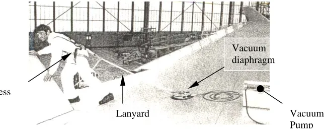
[image:30.595.166.490.578.707.2]• A recent approach for temporary safety anchors for wide body aircraft is the innovative use of a vacuum diaphragm device powered from a pneumatic source that can be used as a WPS anchor for use on aircraft upper wing surfaces. The WinGrip device shown in Figure 2. uses a pneumatic driven vacuum pump to attach a large diameter diaphragm to a smooth almost flat surface.
Figure 2.2. Work Positioning System; the WinGrip System uses an innovative vacuum pad solution for preventing falls from height while working on-top of aircraft structures near an exposed edge.
The equipment is intended for use by a single worker who can carry the 5.5.kg device and quickly set it up on the wing surface, then attach his harness/ lanyard for restraint while working. (WinGrip Rota Limited West Midlands England Revision 4, Jan 2000)
• Individual Fall Arrest Systems. Independent fall arrest systems (IFS) are used to arrest falls near unprotected edges, the systems differ from WPS in that IFS may not provide continuous support but becomes effective in the event of a fall. The state and territory OH & S regulations refer to Australian Standard 1891 Industrial fall-arrest systems and devicesfor settingout requirements and recommendations;
A worker at risk of a potential injury producing fall is to be secured by an appropriate fall arrest system that will:
• Will not be subjected to an arresting force not exceeding 6 kN.
• Wear equipment that will distribute fall–arrest forces over the body in a way that will minimize the possibility of injury.
• Be connected to a system that will prevent the user reaching the ground or striking any other obstacle that could cause injury and will maintain a suitable post fall attitude for rescue.
2.7.3.6. Industrial Rope Access Systems
Industrial rope access systems (IRAS) give a worker access to an elevated worksite below an anchor using rope descent/ascent techniques that have been developed by a Joint Technical committee represented by employer bodies, state government OH & S departments, employee unions, Industrial Rope Access Associations and recreational clubs.
Australia/New Zealand Standard AS/NZ 4488.2:1997 Industrial rope access systems Part 2: Selection, use and maintenance Appendix A page 15 describes a typical method for IRAS that draws from the European Standard EN 567 Mountaineering equipment, rope clamp, safety requirements and test method.
The system utilizes two independently secured lines for ascent/descent procedures
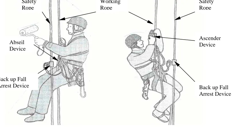
• A working line is used to support the worker and his equipment load. The worker is connected to the working line by a descender attached to his harness for descending, refer to Figure 3(a). and by ascender rope grabs attached to his harness when ascending, refer to Figure 3(b).
• A safety line provides security in the event the working line or its anchor or attachment fails. The worker is connected to the safety line by a rope grab attached by a lanyard to his harness.
.
Figure 2.3.(a). Industrial Rope Access Descent. Figure 2.3.(b). Industrial Rope Access Ascent. Descender device used on Ascender devices used on working rope, back-up rope working rope, back-up rope grab used on safety rope. grab used on safety rope.
The system allows for three operation modes:
• Descent only using a descender where the worker progressively controls his descent to a lower work-site in incremental stages as the back up rope grab on the safety line must be physically repositioned lower as the worker descends.
• Descent only using two ascenders the worker incrementally descends by climbing down the working rope alternately unweighting one ascender at a time and moving it down and repeating the process for the next ascender. The back up rope grab must be physically repositioned lower each time.
• Ascent using only the ascenders, the worker incrementally unweights one ascender and moves it up repeating the process to gain height with each The rope grab is also physically moved up each time.
Considerations for setting up of IRAS:
• Rope Access Systems give direct access to a an elevated work-site directly below an anchor
point. Careful thought must be given on how to position anchors so that a worker is able to comfortably work within his reach. Redirection anchors may be required to allow the working and safety ropes to be positioned sideways to
each the work-site.
• Rope protection at points where abrasion or other damage to the work and safety lines may be needed using protective sleeves or rollers systems.
Safety Rope
Working Rope
Safety Rope
Abseil Device
Ascender Device
Back up Fall Arrest Device Back up Fall
[image:32.595.92.497.146.369.2]• Energy absorber is required to be incorporated between the worker and the safety line so that the maximum force of an arrested fall does not exceed 6kN.This can be done by incorporating an energy absorber in the safety line or by using a personal energy absorber in the lanyard.
2.8. Fall Prevention Methods Used in Recreational Areas
In Australia, equipment and systems used in the outdoor recreation areas of rock climbing, abseiling and caving have evolved not from a strict regulatory frame work but from a sensible approach by users that has been greatly influenced by a number of very unique innovations in equipment design, manufacture and application.
Outdoor sports encompass many forms of fall arrest systems for use in either ground up or a top down approach that allows the user to identify and reduce the risk and hazard levels to a level that would be deemed unacceptable for industrial use.
The four main areas where forms of fall-arrest systems are used in recreational activities are:
2.8.1. Abseiling.
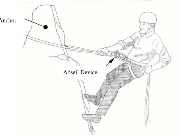
Abseiling is a controlled descent of a rope using friction between the abseil device and a fixed rope to control the rate of descent. By increasing the load on the free end of the rope, the abseiler will increase the friction between the rope and the abseil device, which slows the abseilers descent. Figure 4. Shows the basic equipment used by an abseiler.
Figure 2.4. Abseiling Descent; a single or double rope is fixed to a solid anchor point, the abseiler is connected by a descender device to the rope and his harness. The abseiler can control his rate of descent by adjusting the friction through the systemby increasing the load with his left-hand grip.
Ropes generally used are 9 to 11 mm diameter low stretch “static” ropes of 50 metres long. The ropes can be rigged as a single strand by attaching the rope to anchors at the top of the pitch or the rope can be rigged for retrieval at the base of the pitch by looping the rope
[image:33.595.140.440.420.645.2]around the anchor point and abseiling down the doubled rope, then pulling one end of the rope down afterwards.
At the top of a pitch fall protection using a lanyard is employed to prevent an abseiler reaching an unprotected edge while connecting to the abseil rope.
If an abseiler gets into difficulties during the descent, a person standing at the base of the pitch is able to lock/control the abseilers descent rate. By pulling on the free ends of the rope the person can effectively “brake” the abseilers fall, Figure 5. refers. (Montgomery N. Single Rope Techniques p.68 1977
Figure 2.5. Bottom Belay Braking; an abseilers descent can be stopped/controlled by increasing the friction through the descent device by a person pulling on the free ends of the rope.
2.8.2. Caving.
Systems used in caving allow a person to descend, traverse and ascent areas inside a cave where there is a height hazard or the risk of a fall. Abseiling systems are adapted for use in caves by using the same rope to for ascending if required, Figure 6 shows one method of using two ascender rope grabs to allow a caver to safely ascend a rope. Unlike IRAS, a back-up safety line is not used.
Figure 2.6. Frog Method of Ascender Rope Grab attachment; two ascenders are used – one directly attached to the cavers sit harness, the second to both feet by lanyards/cord. An alternating sit-stand position allows the caver to progressively ascend the rope.
Foot Ascender
While the risk may be increased by not using a safety line, it allows a large reduction in descent and ascent times. Low stretch static ropes are required to be used to avoid excessive rope bounce, which can lead to rope abrasion on the cave surfaces particularly during prussik ascents using ascenders. Dynamic ropes also suffer internal damage due to mud/dust particles from the cave environment penetrating the looser outer rope sheath of the rope where it can internally wear the rope core during use. The tighter sheath weave of a static rope prevents this. For safe passage through a cave, horizontal fixed safety ropes can be rigged to allow a person to traverse across hazardous areas, fall prevention two point lanyards allow the caver to remain connected to the safety line and bypass intermediate anchors safely. (Montgomery N., Single Rope Techniques p.37 1977)
Portable flexible cable ladders are also used for descent/ascent in some caves. The fall arrest method is by using a dynamic rope belay to arrest a caver if he falls from the ladder, refer Figure 7. below. A second caver is positioned at the top of the ladder connected to separate anchors to that of the ladder to control the dynamic rope by pulling in the rope as the caver ascends the ladder. If the caver falls the belayer can lock the belay rope to arrest the fall.
Figure 2.7. Dynamic Rope Belay of a Caver Climbing a Caving Ladder to Provide Fall Arrest.
2.8.3. Rock-Climbing.
Fall arrest methods used in rockclimbing are the most advanced of the recreational outdoor sports.
The systems using high energy absorbing “dynamic” ropes and innovative temporary friction anchors that have been developed from incremental improvements over many years in materials and equipment design that are able to withstand the large fall forces generated. The systems have allowed extreme forms of climbing to develop as the inherent risks have been significantly reduced:
• Lead Climbing. To reduce the risk of a fall a lead climber places intermediate anchors using the natural rock formation and a selection of mechanical friction devices placed at regular intervals on the pitch to allow the safety rope to be connected to. In the advent of a fall the lead climber will fall as far down as the last anchor plus the distance he was above the anchor while his second uses his belay device to lock and arrest the fall, Figure 8. below shows the lead climber/ second climber team during a climb.
Figure 2.8. Rockclimbing Fall Arresting; climb leader being belayed by second climber
The impact fall force generated in the safety rope by the falling lead climber is absorbed by the safety rope, each anchor point and the belayer.
A fall factor of the ratio of rope distance between the belayer and climber verses the actual climber’s fall distance can be used to find the severity of the impact fall force generated in the rope. The most severe fall is a “factor 2 fall” where the climber falls double the distance of the rope distance between him and the belayer, Figure 9(a). shows a “factor 2 fall”. As a climber progressively climbs a pitch the fall factor reduces as more intermediate anchors are placed and the rope distance between the climber and belayer increases, Figure 9(b). shows the reduced fall factor as a climb is progressed.
The resulting impact force generated in a rope is reduced as fall force are transferred to the intermediate anchors and absorbed by the greater length of rope between the climbers. (Grayson D. Ed Freedom of the Hills pp. 131-135 1992).
• Top Roping. This is similar to the belay method used for caving ladders. After the lead climber has set up an anchor system at the top of a pitch, the lead climber belays the second climber by pulling the safety rope through a belay device connected to the anchors. As the second climbs the rock-face removing the intermediate anchors as he ascends, the lead climber takes in the rope in case the second falls off the climb, Figure 10 below shows this fall prevention methods in use.
Figure 2.10. Top Rope Belay; fall protection for the second climber
• Solo Back Roped Rock Climbing: A solo climber attaches the belay rope to anchors at the base of the climb and connects the rope through a belay device attached to his harness. As the climber ascends the rock, the rope is either manually fed through the device or the rope automatically feeds through the device. The climber protects himself from falling by placing secondary anchors at convenient intervals in the rock face similar to normal climbing practice. In the advent of a fall the belay device locks onto the belay rope when the climber falls past the upper most secondary anchor. Figure 2.11 below shows the basic equipment set up.
Figure 2.11 Solo Back Roped Rock Climb Showing: Anchor Point (1), Belay Device (2) Harness (3) and Belay Rope (4)
2.8.4. Mountaineering
The mountain environment’s climatic conditions, altitude, rock/ice avalanche dangers and glacier crossings pose additional risks to the height hazards associated with mountaineering. Added to the fall prevention/arrest techniques for abseiling, caving and rockclimbing used in mountaineering are:
• Glacier Travel. Gaining access to and from climbs can involve crossing of glaciers where the risk of a fall into a crevasse can be quite high. A pair of climbers will “rope-up” using a 50-metre long 9mm-diameter dynamic rope for use as a safety line. The ends of the rope are directly tied into a climbers harness and the distance between the two climbers is shortened to 15- 20 metres by placing coils of rope over one shoulder and the rope is again tied into the climbers harness. Shortening the rope reduces the possible fall distance into a crevasse. The two climbers move together as a team over the glacier keeping the rope between them relatively taut and will have prussik slings connected to the rope with ice axes ready for action. In the advent of a fall into a crevasse, the belayer is required to act quickly and to use his ice axe to arrest the climbers fall. Once an anchor is made in the ice or snow surface above the crevasse and the rope to the fallen climber is secured to it, the belayer is required to assist or rescue the fallen climber from the crevasse.
(Grayson D. Ed Freedom of the Hills pp. 319-323 1992). Figure 2.12 shows the basic method for glacier travel.
1
2 3
Figure 2.12. Method of Roping up for Glacier Travel
• Fixed Rope. Like the safety line system used in industrial applications, fixed ropes allow safe egress across high-risk areas on a mountain. Fixed lines are generally employed on high altitude mountaineering expeditions where a particular section of the route may be repeated several times during the climb and to allow a line for safe retreat. A single static rope of 7- 9mm diameter of up to 200 metres long may be attached to several intermediate anchors in the rock and ice. Long sections on a route may be set up this way to provide safe passage. The steep-ness of the sections fixed may range from flat crevassed areas to vertical sections of ridges and faces were the risk of a fall may be high. A climber is attached by lanyard connection from his harness to the fixed rope using two karabiners. For ascending the fixed line a climber may use a prussik sling or a handled ascender to provide a “hand –hold” that he moves up the rope as he climbs. For descending, the climber may use a simple descender to allow him to control the speed of descent, or he may elect to simply use a gloved hand to provide sufficient friction on the rope. (Grayson D. Ed Freedom of the Hills pp. 392 to 394 1992)
2.9. Chapter Conclusion
The literature review conducted in this Chapter has highlight several areas relating to fall arrest prevention by exploring the regulatory frame work setup by state government OH&S legislation, and supported by the relevant Australia/New Zealand Standards for use in the workplace. For recreation use, the fall prevention equipment used may be outside of the Australia/New Standard requirements, the equipment selected is generally of a higher quality design and construction.
Evaluation
3.1. Introduction.
3.2. Current Fall Arrest Models Selected for A Critical Evaluation.
3.3. Issues Identified From the Critique Evaluation.
Chapter 3. Current Type 1 Fall Arrest Fall Arrest Device
Evaluation
3.1. Introduction
From the Chapter 2 background literature review for fall prevention methods, Type 1 back up rope grabs where identified as the primary area for this research project.
In this Chapter, four backup rope grabs were selected for critical evaluation. The four devices were selected on the basis of being commercially available in Australia through outdoor recreation shops and industrial safety suppliers and have gained wide acceptance for their specific use.
While three of the four devices have been tested for Australia/New Zealand Standard AS/NZ 1891 compliance for use in industrial applications, one device, the Silent Partner is outside the scope of any Australian or international standard yet it performs equally as well as the other purpose designed devices.
The evaluation criteria us