Article
Real Time Clock based Energy Efficient Automatic
Dual Axis Solar Tracking System
Krishna Kumar.N
aand Venkat Subramaniam
b,*Department of Electronics, PSG College of Arts and Science, Coimbatore, Tamil Nadu, India E-mail: a[email protected], b[email protected] (Corresponding author)
Abstract. This paper describes the design, implementation and performance of a real time clock (RTC) based dual axis solar tracking system and asymmetric solar dish concentrator. Numerous algorithm and functional program methodologies are implemented in order to optimizing the energy efficiency of the RTC based simple electromechanical dual axis solar energy tracking system. In this presented work, a RTC (Real Time Clock) based dual axis solar tracking system and solar dish concentrator is designed, implemented and tested based on current time and photodiode sensor based daily tracking method. In daily morning, the photo diode sensor in solar tracking system is used to align the solar concentrator for the initial position. The developed solar tracking system can follow the sun at various days, months and seasons. So, the solar tracking system needs a RTC (Real Time Clock) in order to leading the solar tracking system in finding sun’s position for the daily, monthly and seasonal movement. So, the combination of both RTC and sensor based tracking system gives the designed solar tracking system as an efficient one. Time based algorithm is successfully performed to various months in order to track the sun. An entire asymmetric solar dish concentrator is covered by 1 x 1 inch glass mirrors. The solar dish concentrator has reached maximum solar concentration with the help of this continuous RTC tracking method. The experiment was conducted in the month of March, April and May 2017. The maximum temperature of 415 oC was recorded at the time of experiment. It is found that thermal power gain of RTC based dual axis solar tracking system is 75% compared to the fixed solar concentrator system.
Keywords: Solar concentrator, embedded, RTC, AutoCAD.
ENGINEERING JOURNAL Volume 22 Issue 1 Received 30 June 2017
1. Introduction
In future, the fossil fuels such as gas, oil and coal will be no longer. These are reasoning for global warming and air pollution problems. The fossil fuel prices increasing day by day due to the demand and rising of the industries and vehicles. We needed clean and absence of polluting energy. This can achieve from our natural renewable energy source. Nature provides various renewable sources. One of the important renewable sources is solar, solar radiation is used to produce the solar thermal power with the help of the solar concentrators. Presently, the following four methods are used to concentrate the solar thermal power such as linear Fresnel system, solar dish system, parabolic trough system, solar tower systems. The performance of the solar dish concentration is strongly depending on the design, sizing the aperture and diameter of the receiver, diameter of the dish, azimuth and elevation angle [1-2]. In order to track the sun a photosensitive sensor and coordinate calculation algorithm is used. The sun tracking process is being done with fine tuning of the photosensitive sensor [3]. Six photo-transistor feedbacks are used to control an automated solar concentrator system. It is two axis tracking system both elevation and azimuth angle controlled by six photo transistor sensors covered with lens [4]. PLC based open loop two axis tracking system is used for solar dish concentrator (SDP) [5]. The efficiency of the manual tracking will be less than the automatic solar tracking system. The efficiency will be increased when the solar irradiation is perpendicular to the receiver. It is done by the automatic tracking system [6-7]. The path of the sun was found with the help of analog and digital techniques along with phototransistors [8]. The PLC based software programming method of two axes solar tracking is used to increase the energy of 41.34% than the fixed system [9]. Portable Dish Concentrator with solar tracking system was increased efficiency to 30% [10]. Spherical solar cooker with automatic PLC and frequency control tracking system produced temperature to 93oC [11]. MPPT algorithm in solar tracking system has produced in 12 to 30% percentage of energy than the fixed system [12]. The combination of electronics and mechanical solar tracking system is used for aligning the solar concentrators. The maximum energy can be yield from this electro-mechanical system [13-14]. FPGA (Field programmable gate array) with MPPT two axis solar tracking system has the various intelligent functions that can be used to achieve automatic sun tracking, initial position for the next day and minimizing the power used by the stepper motor in active time [15]. Hongyi Wang et al designed MPDT (Maximum Power Direction Tracking) with self powered system; it has the potential of producing maximum solar energy by adjusting a small tilt angle without human interrupt. The accuracy of the tracking is +/-1.8 degree and gain is 18.4% [16]. Compared to fixed module, the tracking module generates 13-15% output [17]. The CPC (compound parabolic concentrator) thermal performance was increased, when the system equipped with dual axis solar tracking system. The received energy is more than 75% compared with fixed collector [18]. An equation is used to compare between two collectors. One is fixed and another one is connected with solar tracker. The total amount of energy yield by the tracking system is 57% than non-tracking system [19].A four photo transistor based solar tracking is provides enough accuracy in tracking system. This microcontroller system contains the combination of comparators, sensors output and differential amplifier [20-21]. A solar tracking system designed with PLC (Programmable Logic Control) controller is utilized to follow the sun. It has the function of to track the sun in altitude and azimuth motion. The energy produced by this system is 42.6% compared to non tracking system [22]. In this paper the developed solar tracking system has installed at Thrive Technology, Coimbatore, Tamil Nadu, India. The main aim of this present solar tracking system is directly controlled by real time clock (RTC) device, which provides real time. Based on this real time clock, the tracking device will follow the sun in the atmosphere. This system is not dependent to the sensor. Hence, the data of current time from the RTC device that directly sends to the microcontroller device without any data loses. An I2C protocol is used between RTC device and Microcontroller device for data communication. The main advantage of this protocol is provides quick signal transmission and working in noise environment. A simple mechanical gearing system was used to track the sun in azimuth motion. Therefore, the solar dish concentrator receives the maximum solar radiation. The benefit of this present system is low power, low cost and portable system.
2. The Equation of Solar Position
by the environmental condition and physically. The solar radiation and the angle of solar will change depends on seasonal climates. The maximum solar energy could be yield from concentrators, when the altitude and azimuth angle of concentrators are in solar position. The tracking device is required to place the concentrator at the sun’s position. In order to utilize this solar radiation, it is important to calculate the azimuth and altitude angles.
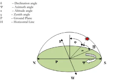
The general solar angle terms are declination angle, azimuth angle, Elevation angle, Incident angle, Zenith angle, Hour angle and inclination angle. Figure 1 shows the angle position of the sun.
δ – Declination angle Ψ – Azimuth angle α – Altitude angle φ – Zenith angle P – Ground Plane H – Horizontal Line
Fig. 1. Solar angle position.
The declination angle is represented by δ. Though, the earth rotation is tilted by 23.5o and the range of the declination angle is -23.5o≤δ≤ +23.5o. This angle is can be calculated by Eq. (1).
)]
284
(
365
360
sin[
45
.
23
d
(1)where ‘d’ is the day of the year. The solar azimuth angle will vary throughout the day and year. The sun rises from east side and sunset’s west side. The azimuth values are 0o for due north, 90o for due east, 180o for due south and 240o for due west. The following Eq. (2) provides the azimuth calculation,
] ) cos( ) cos( ) sin( ) sin( ) sin( [ ) cos( L L
(2)where ’L’ is the latitude (Positive in hemisphere). The vertical angle ‘α’ is denoted as altitude angle. It falls between the of ground plane ‘P’ and sun. The altitude angle is calculated using the following formula,
)] sin( ) [sin( )] cos( ) cos( ) [cos( )
sin(
L
H L D (3) [image:3.595.67.447.174.449.2])
(
90
0
(4))
(
90
0
(5)The solar hour angle will raise 15o by every hour interval. The hour angle will be zero degree at noon time. It can be calculated by the below formula,
)
tan(
)
tan(
)
cos(
H
s
L
(6)The sun rise of an hour angle (Hs) is -180o < Hs<0o and sun set is 0o < Hs<180o.The solar zenith angle (φ) is the angle between sun and the vertical line from the ground plane to the zenith. Summer and winter solstice zenith angle can be calculated using the following Eq. (7) and (8) respectively,
5 . 23 L
(7) 5 . 23 L
(8)From the above equations we can find the sun’s position in a day. According to the sun’s position equation, the tracker system can able to track the sun. The sun’s position can be programmed into the microcontroller in order to follow the sun. The tracking system will be independent to the linearity system.
3. Design of Solar Dish Concentrator
Concentrator is a component used to increase intensity of energy flux incident on the receiver. A compound conical concentrator can be of two design namely, symmetric and asymmetric type. Using computer aided design (CAD) tool, the asymmetric oblique compound conical concentrator was designed and tested. The entry aperture of the solar concentrator is elliptical based, and it contains two axes. One is major axis and another is minor axis. Here, the major axis is x and minor axis is y. The half of the major axis ‘a’ and half of the minor axis is ‘b’. The area of an ellipse is calculated in the following Eq. (9):
1 2 2 2 2 b y a x (9)
According to the Ramanujan approximation formula for perimeter (C) of an ellipse is,
]
)
3
)(
3
(
)
(
3
[
a
b
a
b
a
b
C
(10)]
)
(
3
10
)
(
3
[
a
b
ab
a
2
b
2
(11)] 1 4 3 10 3 )[ ( h h b a
(12)Whereas h is (a-b)2/(a+b)2. The focus point of the elliptical aperture entry oblique compound cone concentrator is calculated as the following formula,
x d y f 16 3 (13)
Fig. 2. Concentrator design using CAD tool.
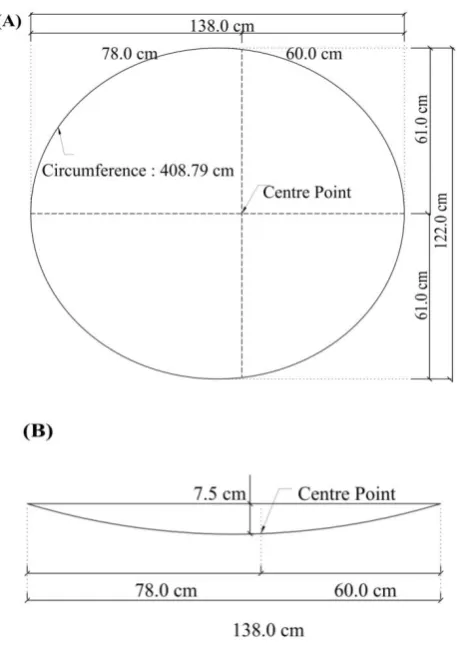
Fig. 3. (A) Top view; and (B) bottom view of the concentrator.
Figure 3(A) is the top view and Fig. 3(B) is the bottom view of the designed concentrator. In Fig. 7(A), the half of the major axis a value is 69cm and half of the minor axis is b value is 61cm. Depth of the concentrator is 7.5cm. The focal length of the designed system is 109.65cm. The system is a simple electro-mechanical system, easy to maintain, low cost and portable. The proposed electro electro-mechanical system is used to produce the maximum amount of energy from the sun energy for various heating applications such as melting, boiling etc. It could be achieved with the help of embedded system automation. The dimension of each mirror on surface of concentrator is 1 by 1 inch. The proposed dish concentrator collects the sun's energy incident on the surface and using 1450 mirrors.
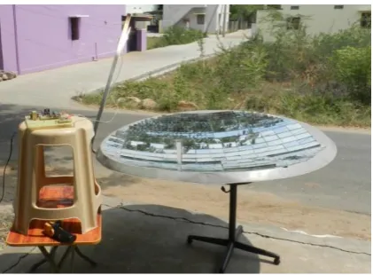
[image:5.595.182.416.92.241.2] [image:5.595.185.415.274.602.2]Sun’s position changes all the time. Hence, the sun tracking system must be aligning and the tracking system must produce the highest possible solar power. The total amount of power generated by solar system depends on the total amount of sunrays which it is uncovered. The solar tracking systems can be categorized as single axis, dual axis, and multi-axis tracking system. Single axis solar tracking system is can be used to track the sun in either east-west direction or north-south direction and it allows the mechanism to rotate only one direction. The dual axis solar tracking system can be track the sun in both directions i.e. from east-west and from north-south. The efficiency of single axis tracking system is lower than that of two axes tracking systems. Figure 4 shows the model of the present solar concentrator with tracking system. The present system divided into two main parts.
A. Mechanical Design Part
B. Electronic Control Unit (ECU) Part
Fig. 4. Experimental system.
A. Mechanical Design Part
Designing the mechanical part is the most difficult part of this present system, because the important objective is to design an efficient energy solar tracking system for developed concentrator. In this solar tracking system, the mechanical design part consists of stepper motor, gear wheel, screw, bearing, bolt and base stand. There are two stepper motors used to rotate the concentrator in order to follow the sun. One of these motor is used to rotate the concentrator in azimuth direction, which is consists of two gear wheels. One is 16 teeth small gear is attached to the stepper motor which is called driving wheel. Another one is 120 teeth gear, which is connected to the rotatable circular rod. A base plat is connected on the circular rod, where the solar concentrator is placed with tilting adjustment. The larger number of teeth gear is driven by the small gear. The ratio between these two gears is 7.5:1 and other motor is used for zenith angle alteration. Normally one of these motor is used for initial position alignment of the solar concentrator in east direction with the help of photodiode sensor. After this, it starts daily rotational moment using RTC (Real Time Clock) and other motor for linear motion.
B. Electronic Control Unit Part
The entire electronic control unit (ECU) is including sensor unit, control unit and measurement unit. Various parameters such as time and position are senses by sensor unit and send the signal to the control unit. After receiving the signal from the sensor unit, the control unit controls the stepper motor direction (clock and anti-clock wise direction) by sending appropriate signals to the driver unit. The driver unit receives the electrical signal from the control unit and adjusts the direction of the stepper motor which is connected with the gear wheel. After aligning the concentrator to the sun’s position, the temperature sensor at the receiver point senses the focused solar radiation temperature and converts it to electrical signal. Then it will send to the measurement unit in order to display the obtained temperature.
[image:6.595.194.405.238.393.2]The sensor unit includes two sensor modules. One is RTC (Real Time Clock) sensor and another one id photodiode sensor. RTC sensor is a device that gives real time and used to track the current time. We have used DS1307. The RTC device provides date, time, year and the device which automatically adjusts the month (30 days or 31 days) and leap year. The RTC device is always connected with the 3V lithium backup battery and it has inbuilt power sensing circuit which is used to detects the power failure and switched to backup battery mode. So, it has the facility to keep track of the real time when the power failure is arise. Microcontroller and RTC device is connected I2C protocol, which is bidirectional bus. The data can be share via these two lines namely SCL (Serial Clock) and SDA (Serial Data). RTC device stores the data in the BCD (Binary Coded Decimal) format. The microcontroller device used BCD data format to send the data to RTC and receive the data from the RTC via bidirectional bus. Microcontroller receives the minute’s values from the RTC device and controls the tracking position of the solar concentrator. Another sensor is photo diode sensor which is used to detect and measure the light intensity. The initial position of the sun is detected by using photo diode sensor which gives corresponding output when it faces the sun.
b) Control Unit
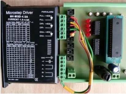
The control unit consists of microcontroller, stepper motor, gear, driver unit, SMPS. This developed mechanism can be rotate in two axes. One is azimuth motion and one is zenith motion. The developed tracking system will track the sun according to the real time. Tracking details are programmed into microcontroller unit as per season. The microcontroller device fetches the timing data from the RTC in order to track the sun in azimuth motion.
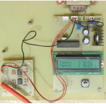
Fig. 5. ECU unit.
Real time clock (RTC) is used as timing device and this RTC device uses a DS1307 serial real-time clock IC. It has 64K bytes of NV- RAM. The data are stored in BCD format into RTC. It can provide clock/calendar in the form binary coded decimal format. This clock/calendar provides the information of time (seconds / minutes / hours), day, date, month and year. The device automatically adjusts the end of the month date and correction for leap year. It also provides hour format with indicator i.e. 12/24 hour or AM/PM. The important feature of this device is in-built power sensing circuit. A 3V lithium back up battery also connected with this sensing circuit, which is automatically switches to back up battery mode when the primary power supply failures. A simple I2C bidirectional bus concept is interfaces between RTC and microcontroller, which provide an effective communication between these two devices. RTC completely supervises time regularity functions. The present system is designed with master and slave concept. The data are controlled by a device is called as master. In this system microcontroller unit act as master device. RTC is a slave device and it is controlled by master device. The entire messages are transferred within START and STOP condition. Standard mode of data transfer in I2C bidirectional bus is in the rate of 100 kHz clock rate and fast mode is 400 kHz. An external 32.768 kHz crystal oscillator is used RTC device. The clock accuracy depends upon crystals accuracy.
[image:7.595.194.400.364.518.2]the real time information from the slave device RTC and controller unit checks the real time with predefined time which is programmed into microcontroller unit. The RTC device changes into a low current backup battery mode, when the power supplies failure or falls below the backup battery voltage (1.25xVBat). The ampere in lithium battery is 48mAh which provides 10 years in the absence of power. When the current time matches with programmed time, the microcontroller unit sends the signal to the stepper motor driver unit. The output from the driver unit will operate the stepper motor. It will rotate step by step. Stepper motor was attached with two gearing system. One is 16 teeth small gear and one is 120 teeth big gear. Azimuth movement of the concentrator is controlled by this gear system. Hence, the concentrator observes the maximum of solar radiation on the surface of solar concentrator and the rays are reflected into receiver area in order to reach maximum temperature. LCD is used to display the temperature. A slight tilt angle variation is also helped to attain a maximum temperature. Tilt angle variation can adjust manually by once in a month. Location of the sun can be identified based on time, so the tracking system moves the concentrator in sun’s path. Solar collector is a concentrator to collect solar energy on its surface. Small pieces of glasses are used as a reflector on concentrator surface and reflected rays are received by the receiver. To achieve better concentration and better performance, the concentrator is equipped with automated embedded system. The objective of present work is helps to provide collector performance using RTC based embedded automation. The current time will display on LCD and user can also changes the time by using push button proficiency.
Initially, the solar concentrator is mounted towards the sun’s position. Microcontroller unit will fetch the present timing data from the real time clock device and also check the current time whether it has reached 10.00am. The tracking system will rotate the concentrator at every 3 min with an angle of 3.6o from 10.00 am to 12.00 pm. When the timing reaches 12.00 pm, the embedded system will change the rotation of the concentrator at every 4 min with the angle of 3.6o from 12.00 pm to 2.00 pm. The solar tracking system is rotating the concentrator in different timing interval and also in different angle. The entire set up is software driven. The main advantage of the developed system is linear, sensor independent and low power consumption. The mechanical unit receives the inputs from the microcontroller and places the solar concentrator into respective degree. Microcontroller unit sends command data to the motor depending upon the time from the RTC. When the time reaches at 3.00 pm the automation will stop and the system will go back to 10.00 am position for next day. The measurement of energy is done using the microcontroller based embedded system can be recorded in the regular interval of small duration of time using RTC. The amount of total steps of the stepper motor is programmed.
Fig. 6. Temperature measuring unit.
c) Measurement Unit
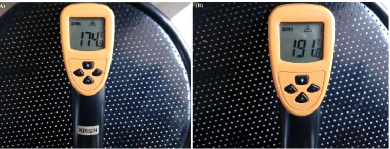
[image:8.595.209.389.462.639.2]Fig. 7. (A) and (B) temperature recording using thermal gun.
Figures 7(A) and 7(B) show various temperature measurement using thermometer gun during the experiments. The temperature was recorded from the month of February and March. The highest temperature of 415 oC is recorded using thermal gun at the time of experiment. The solar tracking device will re-arrange the concentrator for next day’s beginning position.
5. ExperimentalResults and Analysis
The performance of the proposed system was studied and report taken for the month of February and March 2017. The solar tracking mechanism was tested from morning 10.00 AM to 3.00 PM and the temperature were recorded. Received temperature has been measured by two methods. One is K-type thermocouple temperature sensor and temperature range of the K-type thermocouple is -200 to 1350 oC. The output voltage of the thermocouple is 0.041 mV per degree. Microcontroller can’t operate 0.041 mV level. An amplifier circuit is required to convert from 0.041mV into 41mV. So, the microcontroller can able to calibrate this voltage level. Another one is an infrared thermometer gun and temperature measurement range is -50oC to 530oC.
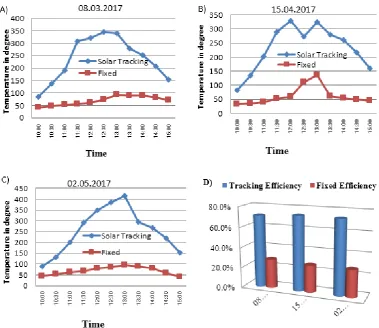
The temperature values were noted with a different time interval. The experiments were tested for a total amount of 90 days. Temperature measurements were executed in the specific time interval as per software driven program. To calculate the performances of the developed tracking system is compared with fixed system. Both the system experimented simultaneously and temperatures were recorded for both system. According to the obtained results and environmental conditions, the monitoring days were categorized as three sections,
section A:Clear sky
section B:Dull sky
section C: Partially Clear sky
[image:9.595.111.491.78.223.2]software program was written into microcontroller device in order to capture maximum temperature at every minutes of time. A small title angle and azimuth rotation generates the highest possible energy. Figure 8 shows the graphical representation of the various environmental conditions. The total amount of energy produced by the concentrator in various days has represented as graphical diagram. The graphical representation clearly tells that the efficiency of the developed solar tracking system. Figure 8(D) shows the percentage of efficiency between solar tracking system and fixed system. The maximum temperature reaches in noon time and decreases on sunset. The results of the designed RTC based embedded automatic tracking system is used to reach the maximum temperature which was 415 oC recorded.
Fig. 8. A) Clear sky; B) Dull sky; C) Partially clear sky; and D) Percentage of efficiency.
6. Conclusion
[image:10.595.108.488.199.527.2]setups were developed and investigated for 90 days observation. From the observed results, it is clearly proves that the RTC based solar tracking system output is more than the fixed system. While tracking, the mechanical errors are arrested by correction factor in software. Absence of sensors may not introduce environmental and physical errors. Automatic power failure detection and switching circuit is added advantage in RTC device. As the lithium backup battery provides supply to RTC device, hence the real time data will not get loss. The presented system can also be implemented for solar PV system. However, the developed system is low cost, low power consumption and compatible.
References
[1] A. Z. Hafez, Ahmed Soliman et al, “Design analysis factors and specifications of solar dish technologies for different systems and applications,” Renewable and Sustainable Energy Reviews, vol. 67, pp. 1019–1036, 2017.
[2] S. Skouri, A. B. H. Ali, S. Bouadila, M. B. Salah, and S. B. Nasrallah, “Design and construction of sun tracking systems for solar parabolic concentrator displacement,” Renewable and Sustainable Energy Reviews, vol. 60, pp. 1419–1429, 2016.
[3] J. Song, Y. Yang, Y. Zhu, and Z. Jin, “A high precision tracking system based on a hybrid strategy designed for concentrated sunlight transmission via fibers,” Renewable Energy, vol. 57, pp. 12-19, 2013. [4] J. Zeaiter, M. N. Ahmad, D. Rooney, B. Samneh, and E. Shammas, “Design of an automated solar
concentrator for the pyrolysis of scrap rubber,” Energy Conversion and Management, vol. 101, pp. 118–125, 2015.
[5] Z. M. Omara and M. A. Eltawil, “Hybrid of solar dish concentrator, new boiler and simple solar collector for brackish water desalination,” Desalination, vol. 326, pp. 62–68, 2013.
[6] A. K.Bidotnark and N. Türkmen, “Modeling of a hot box solar cooker,” Energy Conversion Management, vol. 37, pp. 303–10, 1996.
[7] A. H. Algifri and H. A. Al-Towaie, “Efficient orientation impacts of box type solar cooker on the cooker performance,” Solar Energy, vol. 70, pp.165–70, 2001.
[8] P. J. Hession and W. J. Bonwick, “Experience with a sun tracker system,” Solar Energy, vol. 32, pp. 3– 11, 1984.
[9] S. Abdallah and S. Nijmeh, “Two axes sun tracking system with PLC control,” Energy Conversion and
Management, vol. 45, pp. 1931–1939, 2004.
[10] F. M. Mohamed, A. S. Jassim, Y. H. Mahmood, and M. A. Ahmed, “Design and study of portable solar dish concentrator,” International Journal of Recent Research and Review, vol. 3, pp. 52-59, Sept. 2012. [11] R. Abu-Malouh, S. Abdallah, and I. M. Muslih, “Design, construction and operation of spherical solar
cooker with automatic sun tracking system,” Energy Conversion and Management, vol. 52, pp. 615–620, 2011.
[12] G. C. Lazaroiu, M. Longo, M. Roscia, and M. Pagano, “Comparative analysis of fixed and sun tracking low power PV systems considering energy consumption,” Energy Conversion and Management, vol. 92, pp. 143–148, 2015.
[13] H. Mousazadeh, A. Keyhani, A. Javadi, H. Mobli, K. Abrinia, and A. Sharifi, “A review of principle and sun-tracking methods for maximizing solar systems output,” Renewable Sustainable Energy Review, vol. 13, pp. 1800–18, 2003.
[14] B. J. Huang, W. L. Ding, and Y. C. Huang, “Long-term field test of solar PV power generation using one-axis 3-position sun tracker,” Solar Energy, vol. 85, pp. 1935–44, 2011.
[15] J.-H. Chen, H.-T. Yau, and T.-H. Hung, “Design and implementation of FPGA-based Taguchi-chaos-PSO sun tracking systems,” Mechatronics, vol. 25, pp. 55–64, 2015.
[16] H. Wang, T. Luo, Y. Fan, Z. Lu, H. Song, and J. B. Christen,”A self-powered single-axis maximum power direction tracking system with an on-chip sensor,” Solar Energy, vol. 112, pp. 100–107, 2015. [17] A. Şenpinar and M. Cebeci, “Evaluation of power output for fixed and two-axis tracking
PVarrays,”Applied Energy, vol. 92, pp. 677–685, 2012.
[18] A.-J. N.Khalifa and S. S. Al- utawalli, “Effect of two-axis sun tracking on the performance of compound parabolic concentrators,” Energy Conversion and Management, vol. 39, no. 10, pp. 1073–1079, 1998. [19] H. Mousazadeh, A. Keyhani, A. Javadi, H. Mobli, K. Abrinia, and A. Sharifi, “A review of principle and
[20] S. N. Rumala, “A shadow method for automatic tracking,” Solar Energy, vol. 37, no. 3, pp. 245–247, 1986.
[21] V. Poulek and M. Libra, “New solar tracker,” Solar Energy Materials and Solar Cells, vol. 51, no. 2, pp. 113–120, 1998.
[22] C. Sungur, “Multi-axes sun-tracking system with PLC control for photovoltaic panels in Turkey,”