Article
Dependency Types Validation of Precedence
Diagram Method Using Ontology
Wisarat Srisungnoen
a,*and Wiwat Vatanawood
bDepartment of Computer Engineering, Faculty of Engineering, Chulalongkorn University, Bangkok, Thailand
E-mail: a[email protected] (Corresponding author), b[email protected]
Abstract. Precedence Diagram Method (PDM) is a visual representation technique that
depicts the activities involved in a project. It is a tool for scheduling activities using nodes to represent activities and their connections with arrows to illustrate activity dependencies. During project execution, activities in the project may be considered to change and may lead to inconsistency of dependency types. Consequently, dates and deadlines are missed so these mistakes could prove very costly. Since an ontology describes the relationship between the concepts within a domain. Thus, the ontology could be used to represent knowledge of PDM. This paper proposes PDM Ontology in OWL and rules for inferring the new knowledge from existing PDM and validating PDM using SWRL.
Keywords: Precedence diagram method (PDM), dependency type validation, ontology,
OWL, SWRL.
ENGINEERING JOURNAL Volume 22 Issue 5
1.
Introduction
Precedence Diagram Method (PDM) [1] is a project management tool that helps project managers plan and monitor task schedule throughout the project. The advantage of using PDM is to depict the scheduling activities involved in the project as nodes and their connections with arrows that show dependencies among activities. However, if activities under the project are changed quite frequently, such as adjusting the time interval of an activity, changing the dependency type between activities. Adjustment of an activity may affect other activities and their dependencies types. Consequently, it may cause the project timeline later than planned because of incorrect timeline calculation which could prove very costly.
In the recent past, a number of dependencies and precedence relations handlings related with project scheduling activities to minimize the project duration have been proposed in many research papers in various approaches for example Dependency Structure Matrix (DSM) [2], [3], [4], Linear programming [5], and Branch-and-bound procedure [6]. However, we consider that in this line of research lacks the formal model representation of activity dependencies for further validation.
Since the ontology [7] has the ability to define a semantic model of the data combined with the associated domain knowledge so that it could be used to represent the conceptual meaning of the PDM.
Thus, this paper aims to propose an OWL ontology that describes the semantic of PDM. It depicts activities and dependencies among them and represents two types of SWRL rules. The first set of rules is used to infer the new knowledge from the existing PDM which could be automatically derived from the logical facts and the second set of rules is used to validate PDM and returns as the validation results.
Section II provides the background of the PDM, ontology and its specification language. Section III introduces the methodology to model PDM ontology. Section IV proposes the design of SWRL rules. Section V shows the experiment. Then section VI is the conclusion.
2.
Background
2.1. Precedence Diagram Method
Precedence Diagram Method (PDM) is a networking technique [8] that commonly used as a project management to facilitate project manager in planning and scheduling. Although, there are several networking techniques that enable scheduling activities, for example, Critical Path Method (CPM)[9] and Program Evaluation and Review Technique (PERT)[9]. However, PDM is more flexible network approach to modeling large projects than conventional PERT/CPM [10], [11]. In addition, the Project Management Institute (PMI) publishes the Project Management Body of Knowledge (PMBOK) [3], which collects management knowledge as a guideline for project managers is also discussed and recommended PDM as a tool to scheduling activities.
Precedence Diagram Method (PDM) [1]is an extension of Activity on Node (AON) which represents schedule activities in a project by nodes and their connections with arrows to depict dependencies between the scheduled activities.
Fig. 1. Activity nodes of the PDM [1].
An activity node of the PDM, shown in Fig. 1, contains the following information:
Activity is an activity that needs to be done in the project.
Duration (DUR) is the time interval of the activity to be taken, specified by day.
Earliest start (ES) is the fastest date to start an activity.
[image:2.595.104.495.585.659.2] Latest start (LS) is the slowest date to start an activity that does not affect the project plan.
Latest finish (LF) is the slowest date to complete an activity that does not affect the project plan.
Total float (TF) is the time interval of an activity that could be delayed but it must not affect the project plan. It could be calculated as TF = LF - EF or TF = LS - ES.
Each pair of the activities is connected by one of four types of dependencies shown in the Table 1, Finish to Start (FS), Start to Start (SS), Finish to Finish (FF), and Start to Finish (SF). This is an important feature of PDM.
Table 1. Meaning and symbols of PDM dependency types [12].
Dependency type Symbol Description
Finish-to-Start (FS) Activity B could not start until activity A has finished. This is the most commonly used dependency.
Start-to-Start (SS) Activity B could not start until activity A has started, or both activities must start at the same time.
Finish-to-Finish (FF) Activity B could not finish until activity A has finished, or both activities must finish at the same time.
Start-to-Finish (SF) Activity B could not finish until activity A has started. This dependency is rarely used.
2.2. Ontology
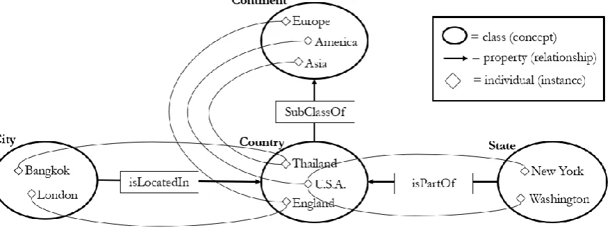
An ontology [13] describes the relationships between the concepts within a domain, so these concepts could be interpreted correctly and stored in the formal specifications or machine-readable format. The use of formal representation could help to clarify concepts and relationships under the domain. It also supports sharing, reusing, inferring the new knowledge from the existing one [7]. An ontology consists of the following parts: [14]
Concept is an interesting domain; therefore, it could be the description of anything, often organized
in taxonomies and having attributes e.g. concept of Place, Country, State, City
Relation is a type of relationship among concepts in the domain, such as the subclass-of relation
which describes the hierarchical structure between two concepts. For example, country has
SubClassOf relation of concept Place.
Function is the property used to describe the concept. It is a special type of relation that returns an
instance of a single concept.
Instance is an element of concepts, for example, according to the concept of the country the
instance could be Thailand.
Axiom is a logical expression that must always be true. In other words, an axiom is a constraint
Fig. 2. An example of country ontology.
The ontology could be processed by reasoning tool [7]. With the existing reasoning techniques, the new knowledge in terms of ontology could be inferred concerning the semantic and instances of the ontology.
2.3. Ontology Web Language (OWL)
Web Ontology Language (OWL) [15] is a language developed by the World Wide Web Consortium (W3C) based on XML. It aims to increase the capabilities of the RDF and RDFS [16], so that it could describe the concept more meaningful and support the description logic [17], data type, and quantifier. An OWL ontology consists of classes, properties, and individuals [18].
Classes are set of individuals that share some properties.
Properties are binary relationships between individuals.
Individuals are instances of classes in the interesting domain.
Fig. 3. Example components of OWL country ontology.
OWL could be divided into three types [19] depending on the usage.
OWL Lite is suitable for hierarchy and classification of concepts that have been defined in terms of simple sequencing or division. This will help to find answers quickly. The Thesauri and Taxonomy are arranged in a hierarchical fashion.
[image:4.595.189.407.82.256.2] [image:4.595.82.523.469.633.2]use. A class could be a subclass of several classes, but the class could not be instances of other classes.
OWL Full is suitable for use with advanced semantic description and more complicated. It is possible to define additional syntax from the RDF and could also define the class to be the instance.
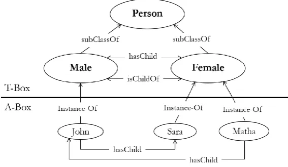
OWL DL is constructed based on description logic [20] which is a family of logic-based knowledge representation formalisms. DL describes domain in terms of concepts (classes), roles (properties, relationships) and individuals. DL syntax consists of two important parts:
1) Terminological Component (T-Box) is a key element of DL knowledge used to build brand
new concepts from the existing or previously defined concepts, and axioms. For example, a man could be defined as a male person by using this declaration:
Man Person ∩ Male
The declaration is interpreted as a logical equivalence by providing enough and necessary conditions to define an individual as a man.
2) Assertion Component (A-Box) is an assertion about individuals. For example, giving the
following declaration statements or axioms:
Male ∩ Person (John) hasChild (John, Sara) hasChild (Matha, John)
states that the individual John is a male person. From the previous definition of Man, one could derive from this assertion that John is an instance of the concept of Man. The same as the second declaration which specifies that John has Sara as a child. So, the basic reasoning task in ABox is instance checking, to verify whether a given individual belongs to a specified concept.
A knowledge comprising of TBox and ABox has a semantics of equivalence set of axioms but the purpose of a knowledge representation system is more than storing concept definitions and assertions [21]. Due to the set of axioms, it provides implicit knowledge that could be transferred to explicit knowledge by using inferences. For example, from the TBox and ABox above one can conclude that Matha is a grandmother, although this knowledge is not explicitly stated as an assertion. So, by using this kind of definition, it could infer the new knowledge in the interesting domain.
[image:5.595.158.442.534.699.2]In this paper, OWL DL [22] was used to describe ontology. It has the capacity to support reasoning by inferring facts and rules so, individuals explicitly introduced in the ABox could apply defined rules and return the validation results.
2.4. Time Ontology in OWL
OWL-Time [23] is an ontology of temporal concepts created by Jerry R. Hobbs and Feng Pan. This ontology applies Allen’s theory [24] to describe thirteen elementary relations which support the unambiguous expression of all possible relations that will occur in the time interval. So, it could describe the activities which are linked by dependencies and occur in a sequence. It facilitates information about durations and temporal position as shown in Table 2.
OWL-Time also provides specific predicates to support or to make explicit the results of, reasoning over the sequence of activities which could help with queries and reasoning applications. Hence, in the Ontology modeling part, we would derive properties in the ProperInterval class from the OWL-Time ontology into our ontology.
Table 2. Thirteen Element Relations between Time Periods Based on Allen’s Theory [23], [24].
Relation Definition Inverse Example in PDM
intervalBefore If an interval A is intervalBefore
another interval B, then the end of A is before the beginning of B.
intervalAfter
intervalMeets If an interval A is intervalMeets
another interval B, then the end of A is coincident with the beginning of B.
intervalMetBy
intervalOverlaps If an interval A is intervalOverlaps
another interval B, then the beginning of A is before the beginning of B, the end of A is after the beginning of B, and the end of A is before the end of B.
intervalOverlappedBy
intervalStarts If an interval A is intervalStarts
another interval B, then the beginning of A is coincident with the beginning of B, and the end of A is before the end of B.
intervalStartedBy
intervalDuring If an interval A is intervalDuring
another interval B, then the beginning of A is after the beginning of B, and the end of A is before the end of B.
intervalContains
intervalFinishes If an interval A is intervalFinishes
another interval B, then the beginning of A is after the beginning of B, and the end of A is coincident with the end of B.
IntervalFinishedBy
intervalEquals If an interval A is intervalEquals
another interval B, then the beginning of A is coincident with the beginning of B, and the end of A is coincident with the end of B.
-
2.5. OWL and UML Modeling
[image:6.595.63.537.300.705.2]OWL facilitates the description of concepts of the ontology. Thus, an instance object could be assigned to any classes and described by any properties. Therefore, each instance object belongs to a certain class and has its own structure.
Unified Modeling Language (UML) [25] is a visual modeling language which uses graphical notations to specify, visualize, construct and document the model in many aspects of software development process.
UML also describes semantic concepts of classes with attributes that define the structure and their behavior of the modeling elements.
Although UML and OWL have different objectives and approaches, they are similar regarding structure representation, respectively [26]. Table 2 describes the similar concepts of UML and OWL.
Table 3. Similar concepts of UML and OWL elements [26].
UML Elements OWL Elements
Class Class Subclass Subclass Instance Individual Attribute, Binary association Property Enumeration OneOff
Multiplicity minCardinality, maxCardinality Package Ontology
2.6. Semantic Web Rule Language (SWRL)
Semantic Web Rule Language (SWRL) [27] is a language used to generate rules which are the extension of the OWL. SWRL allows an ontology to infer through the defined rules because it is built on the same description logic foundation as OWL. However, it needs an inference engine, i.e. JESS [28] to be interpreted.
The structure of SWRL rule consists of two parts, an antecedent, and a consequent part. The antecedent part is referred to as the body, and the consequent part is referred to as the head. Both the body and head consist of conjunctions of atom:
atom1 ^ atom2 ^.... ^ atomn → atom
In this case, if all atoms in the antecedent are true, then all atoms in the consequent also be true. SWRL could support only the positive of conjunction form, it does not support negated or disjunction forms.
A statement could be expressed in the form of the predicate:
p(arg1, arg2, ..., argn)
where p is a predicate symbol and arg1, arg2, ..., argn are the terms or arguments of the predicate.
There are only five types of predicates are allowed: OWL classes, OWL properties, data types, data ranges, and built-ins.
Here is the example to represent an OWL class named Person() and Man() with a single argument which contains variable ?p and individual named John respectively as follow:
Person(?p) Man(John)
So, from the two classes statements above, we could construct a rule to infer that all individuals of class Man are also individuals of class Person, so it could be expressed as follows:
[image:7.595.150.444.227.334.2]2.7. Protégé
Protégé [29] is an open platform for ontology modeling and knowledge acquisition developed by Stanford University. It contains the OWL Plugin that provides many features, manipulating ontologies in OWL, accessing description logic reasoners and acquiring instances in the ontology model.
Thus, users simply create classes, assign properties to the classes, and then restrict the properties of the classes by using protégé. Protégé has designed a user interface that is easy to use. There is no need to have knowledge of computer programming language. Additional plug-ins could also be installed so that ontologies could show relationships in a graphical manner. In addition, Protégé could also support inference engine tools named JESS to infer rules created with SWRL.
3.
PDM Ontology Modeling
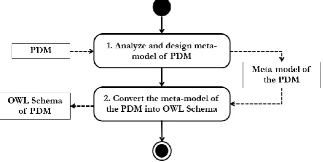
This section provides an overview procedure to design and construct PDM as an ontology. There are two steps starting from the analysis and design of meta model of PDM and then convert it into OWL ontology.
Fig. 5. The procedure to design and construct PDM ontology.
3.1. Analyze and Design of Meta Model of PDM
In this step, we will analyze the components of the activity on the PDM. As shown in Fig. 6,they are preparing activities of an e-bidding procurement, starting from preparing a procurement plan until preparing for the bidding documents, announcement, and procurement report. All these activities must be specified for the starting date, finish date, duration and so on according to the components of PDM. Hence, we will use this example to analyze and design for the meta model of PDM.
There are two main components of PDM which are activity nodes and activity edges. An activity node contains an activity duration and its time-dependent criteria to start and finish including Earliest Start (ES), Earliest Finish (EF), Latest Start (LS), and Latest Finish (LF). An activity edge (arcs or arrows) indicates the precedence relationship which could be in the form of Finish to Start (FS), Finish to Finish (FF), Start to Finish (SF), and Start to Start (SS).
[image:8.595.132.464.286.452.2]From the given PDM in Fig. 6, we could consider that meta-model of the PDM consists of two main classes, the ActivityNode and the ActivityEdge class shown in Fig.4. The ActivityNode class represents the attributes of an activity in the UML class as follows:
Fig. 7. Our UML meta model of the PDM.
nodeName is the name of the activity.
duration is the time taken to complete the activity. The unit is the number of day.
earlyStart is the fastest start date of an activity.
earlyFinish is the day of the fastest finish of an activity.
lateStart is the latest start date of the activity.
lateFinsih is the day of the latest finish of an activity.
totalFloat is the number of the day for each activity that could be delayed without affecting the completion of the project, calculated from (LF-EF) or (LS-ES).
The ActivityEdge class describes the dependency types between two activities as follows:
edgeName is the label of the edge.
dependencyType is the dependency types which consists of 4 types - FS, FF, SF, SS. In addition, there are 2 association relationships of the ActivityNode class as follows:
hasInputEdge describes the incoming activity.
hasOutputEdge describes the outgoing activity.
3.2. Convert the Meta model of the PDM into OWL Schema
The next step is to convert PDM meta model into OWL. Meta model describes the structure of a model in the form of UML class diagram that describes classes and the relationships among them.
[image:9.595.167.522.133.249.2] [image:9.595.75.526.621.747.2]4.
SWRL Rules Design
There are two main types of our SWRL rules, inference and validation rules.
Fig. 9. The procedure to design and construct SWRL rules.
4.1. Design and Construct SWRL Rules to Infer the New PDM Knowledge
[image:10.595.122.485.147.325.2]One major advantage of using an ontology is its ability to infer the new knowledge from existing knowledge. SWRL rules could be expressed with OWL by using the concept of description logics (DL) to infer the new knowledge from the PDM OWL. The architecture of description logic is divided into two parts.
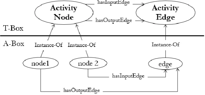
Fig. 10. Our PDM Ontology description logic with T-Box and A-Box.
Terminological Component (T-Box) describes sets of concepts and properties within the domain.
In this paper, we use the ontology to describe the concept of the PDM. The T-Box part in Fig.10 shows the ontology schema of the PDM that the ActivityNode and ActivityEdge are represented.
Assertion Component (A-Box) is used to specify individuals or instances under the concept
designed in the T-Box. The A-Box part in Fig. 10 describes that both activities named node1 and node2 are instances of ActivityNode, which have an instance of ActivityEdge named edge as their connection.
[image:10.595.141.470.449.601.2]PDM:ActivityNode(?node1) ∧ PDM:ActivityNode(?node2) ∧
PDM:hasOutputEdge(?node1, ?edge1) ∧ PDM:hasInputEdge(?node2, ?edge2) ∧
[image:11.595.73.535.330.774.2]sameAs(?edge1, ?edge2) → PDM:isPredecessorOf(?node1, ? node2)
Fig. 11. A sample of inference rules to infer the predecessor node.
In Fig. 11, the inference rule is written in SWRL defines the function to check whether ?node1 occurs before node of ?node2 or not. Given a set of instances described in Fig. 10, both node1 and node2 are the valid ActivityNode and the output edge of A is the same as the input edge of B. With these antecedent axioms, this inference rule yield that node1 is the predecessor node of node2.
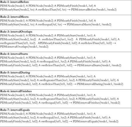
Moreover, we could apply Time Ontology in OWL and SWRL rule to infer the interval relations between connected nodes in the PDM. For example, creating a function to determine whether one activity (node1) occurs before another activity (node2) or not, so we could create a rule in SWRL to answer this question in Rule-1 in Table 4.Table 4 shows all SWRL rules applying Allen’s theory to describe all possible relations between nodes in PDM to allow the computation of any relative position or sequence. Then, our SWRL rules are prepared using Protégé and JESS inference engine plug-in as the reasoning tool.
Table 4. SWRL rules applying Allen’s theory
Rule-1: intervalBefore
PDM:Node(?node1) ∧ PDM:Node(?node2) ∧ PDM:earlyFinish(?node1, ?ef) ∧
PDM:earlyStart(?node2, ?es) ∧ swrlb:lessThan(?ef, ?es) → PDM:intervalBefore(?node1, ?node2)
Rule-2: intervalMeets
PDM:Node(?node1) ∧ PDM:Node(?node2) ∧ PDM:earlyFinish(?node1, ?ef) ∧
PDM:earlyStart(?node2, ?es) ∧ swrlb:equal(?ef, ?es) → PDM:intervalMeets(?node1, ?node2)
Rule-3: intervalOverlaps
PDM:Node(?node1) ∧ PDM:Node(?node2) ∧ PDM:earlyStart(?node1, ?es1) ∧
PDM:earlyStart(?node2, ?es2) ∧ swrlb:lessThan(?es1, ?es2) ∧ PDM:earlyFinish(?node1, ?ef1) ∧
swrlb:greaterThan(?ef1, ?es2) ∧PDM:earlyFinish(?node2, ?ef2) ∧ swrlb:lessThan(?ef1, ?ef2) → PDM:intervalOverlaps(?node1, ?node2)
Rule-4: intervalStarts
PDM:Node(?node1) ∧ PDM:Node(?node2) ∧ PDM:earlyStart(?node1, ?es1) ∧
PDM:earlyStart(?node2, ?es2) ∧ swrlb:equal(?es1, ?es2) ∧ PDM:earlyFinish(?node1, ?ef1) ∧
PDM:earlyFinish(?node2, ?ef2) ∧ swrlb:lessThan(?ef1, ?ef2) → PDM:intervalStarts(?node1, ?node2)
Rule-5: intervalDuring
PDM:Node(?node1) ∧ PDM:Node(?node2) ∧ PDM:earlyStart(?node1, ?es1) ∧
PDM:earlyStart(?node2, ?es2) ∧ swrlb:greaterThan(?es1, ?es2) ∧ PDM:earlyFinish(?node1, ?ef1) ∧
PDM:earlyFinish(?node2, ?ef2) ∧ swrlb:lessThan(?ef1, ?ef2) → PDM:intervalDuring(?node1, ?node2)
Rule-6: intervalFinishes
PDM:Node(?node1) ∧ PDM:Node(?node2) ∧ PDM:earlyStart(?node1, ?es1) ∧
PDM:earlyStart(?node2, ?es2) ∧ swrlb:greaterThan(?es1, ?es2) ∧ PDM:earlyFinish(?node1, ?ef1) ∧
PDM:earlyFinish(?node2, ?ef2) ∧ swrlb:equal(?ef1, ?ef2) → PDM:intervalFinishes(?node1, ?node2)
Rule-7: intervalEquals
PDM:Node(?node1) ∧ PDM:Node(?node2) ∧ PDM:earlyStart(?node1, ?es1) ∧
4.2. Design and Construct SWRL Rules to Validate the Dependency Types Checking
To validate the dependency types of PDM, we need to extract the knowledge from PDM components i.e. time-dependent criteria and its dependency type restrictions. In this paper, we focus on the Finish-to-Start (FS) dependency type as the simulation and mapped to our PDM ontology schema.
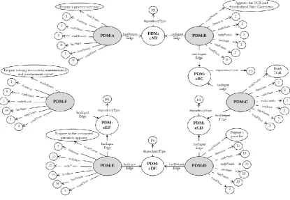
[image:12.595.83.499.228.515.2]To test the SWRL rules, we need to create individual nodes and edges responding to the design ontology schema which have the properties and data type values according to Fig. 6. In Fig. 6., there are six individual nodes with different activities, allow us to represent these activities in alphabet A, B, C, D, E and F respectively to make it easier to explain. All these nodes connect with five individual edges, eAB, eBC, eCD, eDE, and eEF respectively. The resulting ontology knowledge of this PDM is shown in Fig.12.
Fig. 12. A sample of our ontology knowledge of PDM.
Then we need to create a rule to validate whether each pair of nodes having the “FS” dependency type as follows:
PDM:intervalBefore(?node1, ?node2) ∧
PDM:Edge(?edge1) ∧ PDM:DEPType(?edge1, “FS”) ∧ PDM:Edge(?edge2) ∧
PDM:DEPType(?edge2, “FS”) ∧ PDM:hasOutputEdge(?node1, ?edge1) ∧
PDM:hasInputEdge(?node2, ?edge2) ∧
sameAs(?edge1, ?edge2) ∧ PDM:EF(?node1, ?ef1) ∧ PDM:ES(?node2, ?es2) ∧
swrlb:lessThanOrEqual(?ef1, ?es2) ∧
PDM:LF(?node1, ?lf1) ∧ PDM:LS(?node2, ?ls2) ∧ swrlb:lessThanOrEqual(?lf1, ?ls2) ∧
sameAs(?result, PDM:Valid_FS) ∧
PDM:Valid(PDM:Valid_FS) →
sqwrl:select(?node1, ?edge1, ?node2, PDM:Valid_FS)
[image:12.595.103.506.591.742.2]In fig. 13, we intend to check whether the time-dependent criteria between a pair of activity nodes are valid. To be the dependency type of “FS”, the Early Finish (EF) of the first node must be less than or equal to the Early Start (ES) of the second node, denoted as EF <= ES. Whilst, the Late Finish (LF) of the first node must be less than or equal to the Late Start (LS) of the second node, denoted LF <= LS.
5.
Experimental Results
[image:13.595.136.458.278.552.2]In this section, we demonstrate the dependency type validation of the “FS” using the Protégé reasoning tool with JESS plug-in of SWRL inference engine. The first set of our SWRL inference rules are prepared and transferred as the predefined knowledge and functions. In Fig. 14, the ontology and instances of PDM are processed. The result shows that the new knowledge of the PDM ontology concepts indicating that B is also the predecessor of C, and D, is automatically generated. The second set of our SWRL validation rules are also prepared to demonstrate the “FS” dependency type checking. With the given ontology and instances of PDM, the results show the valid “FS” dependency type on the screen shown in Fig. 15.
Fig. 14. The inferred result of the individual activity B after running Jess.
[image:13.595.142.457.592.712.2]6.
Conclusion
In this paper, we construct a PDM ontology analyzed from its structure and constraints. Then, the meta model to describe the context of PDM is designed in UML class diagram. As the concept of elements of UML and OWL are close, then we could convert the UML meta model of a PDM into ontology correspondingly and use Protégé tool to generate OWL ontology. Moreover, we also propose SWRL rules to infer the new knowledge of PDM from the existing ones and SWRL rules to validate the dependency type. Using the example of PDM to test the rules, the experimental results show that our ontology could return the correct validation result.
However, according to the structure of the SWRL rules could support only the positive conjunction form of the antecedent. If one atom in the consequent is false, then it would consider as invalid. Hence, in case of the complex consolidation of the PDM, users could not identify which parts of PDM are invalid.
Future work will focus on developing an application to import OWL PDM in different types of project scheduling and allow our OWL ontology to return the validation result. If it returns ‘invalid’ result, the application could point out the invalid statement that may cause the PDM inconsistency.
References
[1] K. Schwalbe, Information Technology Project Management. Cengage Learning, 2015.
[2] J. U. Maheswari and K. Varghese, “Project scheduling using dependency structure matrix,”International
Journal of Project Management, vol. 23, no. 3, pp. 223-230, 2005.
[3] Q. Shi and T. Blomquist, “A new approach for project scheduling using fuzzy dependency structure matrix,”International Journal of Project Management, vol. 30, no. 4, pp. 503-510, 2012.
[4] I. M. Srour, M.-A. U. Abdul-Malak, A. A. Yassine, and M. Ramadan, “A methodology for scheduling overlapped design activities based on dependency information,”Automation in Construction, vol. 29, pp. 1-11, 2013.
[5] S. Sakellaropoulos and A. Chassiakos, “Project time–cost analysis under generalised precedence relations,”Advances in Engineering Software, vol. 35, no. 10-11, pp. 715-724, 2004.
[6] B. De Reyck, “A branch-and-bound procedure for the resource-constrained project scheduling problem with generalized precedence relations,”European Journal of Operational Research, vol. 111, no. 1, pp. 152-174, 1998.
[7] T. R. Gruber, “A translation approach to portable ontology specifications,”Knowledge Acquisition, vol. 5, no. 2, pp. 199-220, 1993.
[8] G. T. Haugan, Project Planning and Scheduling. Berrett-Koehler Publishers, 2001.
[9] J. W. Fondahl, “A non-computer approach to the critical path method for the construction industry,” 1962.
[10] R. D. Archibald, “The history of modern project management: key milestones in the early PERT/CPM/PDM days,”Project Management Institute, 1987.
[11] J. D. Wiest, “Precedence diagramming method: Some unusual characteristics and their implications for project managers,”Journal of Operations Management, vol. 1, no. 3, pp. 121-130, 1981.
[12] M. T. Callahan, D. G. Quackenbush, and J. E. Rowings, Construction Project Scheduling. 1992.
[13] N. Guarino, D. Oberle, and S. Staab, “What is an ontology?,” in Handbook on Ontologies. Springer, 2009, pp. 1-17.
[14] A. Gómez-Pérez and R. Benjamins, “Overview of knowledge sharing and reuse components: Ontologies and problem-solving methods,” inCEUR Workshop Proceedings, IJCAI and the Scandinavian
AI Societies,1999.
[15] G. Antoniou and F. Van Harmelen, “Web ontology language: OWL,” in Handbook on Ontologies. Springer, 2004, pp. 67-92.
[16] D. Allemang and J. Hendler, Semantic Web for the Working Ontologist: Effective Modeling in RDFS and OWL. Elsevier, 2011.
[17] F. Baader, TheDescription Logic Handbook: Theory, Implementation and Applications. Cambridge University Press, 2003.
[19] D. L. McGuinness and F. Van Harmelen, “OWL web ontology language overview,”W3C
Recommendation, vol. 10, no. 10, p. 2004, 2004.
[20] D. Nardi and R. J. Brachman, “An introduction to description logics,”in Description Logic Handbook, vol. 1, 2003, p. 40.
[21] F. Baader and W. Nutt, “Basic description logics,” inThe Description Logic Handbook. Cambridge University Press, 2003, ch. 2.
[22] B. Motik, U. Sattler, and R. Studer, “Query answering for OWL-DL with rules,”Web Semantics: Science,
Services and Agents on the World Wide Web, vol. 3, no. 1, pp. 41-60, 2005.
[23] J. R. Hobbs and F. Pan, “Time ontology in OWL,”W3C Working Draft,vol. 27, p. 133, 2006.
[24] J. F. Allen, “Towards a general theory of action and time,”Artificial Intelligence, vol. 23, no. 2, pp. 123-154, 1984.
[25] J. Rumbaugh, I. Jacobson, and G. Booch, TheUnified Modeling Language Reference Manual. Pearson Higher Education, 2004.
[26] A. Pătraşcu, “Comparative Analysis between OWL Modeling and UML Modeling,”Petroleum-Gas
University of Ploiesti Bulletin, Technical Series, vol. 67, no. 2, 2015.
[27] I. Horrocks, P. F. Patel-Schneider, H. Boley, S. Tabet, B. Grosof, and M. Dean, “SWRL: A semantic web rule language combining OWL and RuleML,”W3C Member Submission, vol. 21, p. 79, 2004.
[28] M. O’connor, H. Knublauch, S. Tu, and M. Musen, “Writing rules for the semantic web using SWRL and Jess,”Protégé with Rules WS, Madrid, 2005.
![Fig. 1. Activity nodes of the PDM [1].](https://thumb-us.123doks.com/thumbv2/123dok_us/8106845.235335/2.595.104.495.585.659/fig-activity-nodes-pdm.webp)
![Table 2. Thirteen Element Relations between Time Periods Based on Allen’s Theory [23], [24]](https://thumb-us.123doks.com/thumbv2/123dok_us/8106845.235335/6.595.63.537.300.705/table-thirteen-element-relations-periods-based-allen-theory.webp)
![Table 3. Similar concepts of UML and OWL elements [26].](https://thumb-us.123doks.com/thumbv2/123dok_us/8106845.235335/7.595.150.444.227.334/table-similar-concepts-uml-owl-elements.webp)