Ship Product Modeling
R. I. Whitfield, A. H. B. Duffy, J. Meehan,and Z. Wu
CAD Centre, Department of Design Manufacture and Engineering Management, University of Strathclyde, Glasgow, United Kingdom
This paper is a fundamental review of ship product modeling techniques with a focus on determining the state of the art, to identify any shortcomings and propose future directions. The review addresses ship product data representations, product model-ing techniques and integration issues, and life phase issues. The most significant development has been the construction of the ship Standard for the Exchange of Product Data (STEP) application protocols. However, difficulty has been observed with respect to the general uptake of the standards, in particular with the application to legacy systems, often resulting in embellishments to the standards and limiting the ability to further exchange the product data. The EXPRESS modeling language is increasingly being superseded by the extensible mark-up language (XML) as a method to map the STEP data, due to its wider support throughout the information technology industry and its more obvious structure and hierarchy. The associated XML files are, however, larger than those produced using the EXPRESS language and make further demands on the already considerable storage required for the ship product model. Seamless integration between legacy applications appears to be difficult to achieve using the current technologies, which often rely on manual inter-action for the translation of files. The paper concludes with a discussion of future directions that aim to either solve or alleviate these issues.
Introduction
THE SHIP DESIGN process typically involves a large number of
disparate software tools evaluating a variety of characteristics and life phases (structural, operational performance, production sched-uling, etc.) in order to enable the production of a ship design that satisfies the customer’s requirements. The software tools generally produce discrete solutions to a particular problem with respect to a set of requirements. That is, they have their own model and solution representations (Erikstad & Fathi 1999) and are rarely influenced by the interactions with other tools. As such, a large complex ship design project may have multiple representations of different aspects of the same design model, distributed either or-ganizationally, or more commonly, globally. Managing the data within these models to maintain consistency is an important but complicated task.
This paper addresses product modeling techniques and systems that attempt to address these issues by providing a central store of
(neutrally formatted) data that is common to all of the design and simulation tools. The tools can then access these data, add their own embellishments if required, and perform design, analysis, or simulation while maintaining consistency with all of the other software tools. Because the data are shared among the simulation tools, the store of data has often been called the common model. However, within shipbuilding, it is more commonly referred to as the ship product model.
It is generally accepted that each individual life cycle within the development of the ship product is associated with the production and management of a large quantity of complicated and interre-lated product data (Polini & Meland 1997, Catley 1999). The data often relate to geometrical, topological, functional, material, pro-duction, operational, and other aspects of the product. Within the shipbuilding industry, the full life cycle of the product is expected to last more than 20 years (Wyman et al 1997), and in some cases, such as the naval industry, it may be as long as 40 years, posing some important issues with respect to the organization and man-agement of the product model. The representation, requirement, and usage of the ship product model will also vary depending on the current life phase. For example, three-dimensional geometrical
data may be used more extensively within the design and produc-tion life phases, whereas the bill of materials would be more relevant to recycling during the disposal life phase.
These issues have never before been considered within the ad-vent of digital product modeling techniques, because these tech-niques have become prevalent only within the last 10 years or so, and have in general been developed and applied only to the pre-commissioning life-cycle stages. The structure and definitions for the data types within the precommissioning stages are becoming increasingly realized and standardized. However, little consider-ation has been given regarding the nature of the ship product model for the postcommissioning stages, such as operation, main-tenance, refit, and disposal, and the predesign stages of require-ments analysis and feasibility studies. More importantly, due to the duration of the full life cycle of the ship product, it is essential that the data contained within the product model conform to agreed-upon standards such that support may be maintained through a number of generations of computer architectures, oper-ating systems, and ship development environments.
In a brief review of the state of the art of the product modeling technologies, Ross and Garcia (1998) identify a number of char-acteristics that advanced product models possess: a single, inte-grated database; graphical user interface with a consistent format; topological relationships among components of the ship design; macros and parametric tools; and open structure to allow for data retrieval to support manufacturing functions. This paper discusses these characteristics and aims to identify important others through the review of a number of key reports and papers that generally focus on the ship product model.
The paper consists of an introduction to ship product data for-mats; a review of ship product modeling tools, techniques, and projects; life-cycle issues; and a speculation for future develop-ments for ship product modeling.
Ship product data
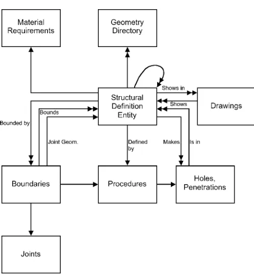
The effective management of information within a database was considered by Martin (1980) to improve the management of the design configuration and to increase the speed and accuracy with which design documentation may be produced. Models contained within the database were created to represent the physical char-acteristics of the product. Figure 1, for example, represents a sim-plified design model for the structure of the ship.
The central component of this model is the structural definition entity (SDE), which represented either a point, a line, a surface, a volume (or region), a plate part, a stiffener, or a group of parts. Information derived from other information contained within the database was not stored in order to reduce the size of the database. Other models were defined based on the SDE to represent piping, and so forth. Despite being one of the earliest pieces of work on product modeling, Martin discussed a number of important char-acteristics of product models that have since been adopted as standard, such as relationships between models to enable the checking of interferences between geometrical components, and storage of information relating to the drawings that may be af-fected by a change to an SDE to improve design management.
The International Standards Organisation (ISO) has for some time been developing a Standard for the Exchange of Product Data
Nomenclature
AP application protocol ARPA Advanced Research Projects
Agency
ASE Advanced Shipbuilding Enterprise CAD computer-aided design
CE concurrent engineering
CORBA common object request brokerage architecture
DARPA Defence Advanced Research Projects Agency
DFP design for production EJB Enterprise Java Beans EMSA European Marine STEP
Association
ESPRIT European Strategic Programme for Research and Development in Information Technology GOBS geometry object structure
GUI graphical user interface IGES initial graphic exchange
specification ISO International Standards
Organisation JMSA Japan Marine Standards
Association
NIAM Nijssen information analysis method
NIDDESC Navy/Industry Digital Data
Exchange Standards Committee OSEB object serialization early binding PDES product definition exchange
standard
SBD simulation-based design SDE structural definition entity SPM Smart Product Modelling SHIIP Shipbuilding Information
Infrastructure Project SPARS Shipbuilding Partners and
Suppliers
STEP Standard for the Exchange of Product Data
[image:2.584.298.547.25.294.2](STEP). STEP is being developed to tackle the issues associated with cross-platform and cross-application development of any de-sign artifact through the production of a system-independent rep-resentation of the product data. Data types, such as geometry, topology, functionality, cost, materials, strength, and so forth, may be modeled using STEP. The STEP application layer contains the neutral data models, and the implementation layer contains the actual implementation of these models. The EXPRESS data mod-eling language was specifically developed for use within the ap-plication layer. STEP has been described as “not only for neutral file exchange, but also as a basis for implementing and sharing product databases and archiving” (ISO, 1996).
STEP is organized as the following series: description methods (10s), implementation methods (20s), conformance testing meth-odology and framework (30s), integrated generic resources (40s), integrated application resources (100s), application protocols (200s), abstract test suites (300s), and application interpreted con-structs (500s).
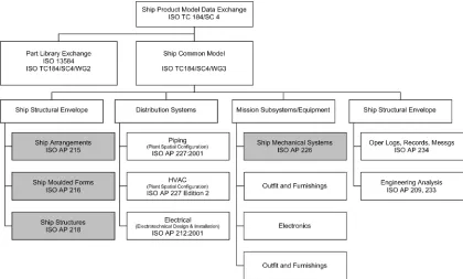
Established in 1985, the Navy/Industry Digital Data Exchange Standards Committee (NIDDESC) was involved in defining an activity model and information models for ship design and con-struction. The ISO is continuing this work through the STEP Ship Team (ISO TC184/SC4/WG3/T23) and has developed a number of application protocols (APs) to represent various aspects of the ship product model (Fig. 2). Herzog and To¨rne (1999) defined an application protocol as being “an information and process model for an engineering domain,” as well as providing additional defi-nitions to the various STEP series.
The ship arrangements model (AP215) was developed to sup-port functional and detail design, and production engineering life-cycle phases to support damage stability, structural analysis, in-terference analysis, and so forth.
The ship molded forms model (AP216) was designed to
repre-sent any geometrical shape for the hull form or internal surfaces that may be used within the design, production, and operation life-cycle phases for hydrodynamic and intact stability analysis.
The ship structures model (AP218) defines the structural parts of the ship, such as the hull structure, superstructure, and internal structures for the predesign, design, production, and inspection life-cycle phases. The ship structures model has links to AP215 and AP216.
The ship mechanical systems model (AP226) is used to define mechanical components, such as main and auxiliary engines, fuel pumps, air compressors, and so forth. AP226 also defines the connectivity between components, geometry, materials, topology, and operational characteristics for the mechanical components.
The electrical design and installation model (AP212) defines the electrical design and installation information for electrical cables and harnessing for power transmission, distribution, generation, and so forth. The AP has been finalized.
The piping and heating, ventilation, and air conditioning (HVAC) model (AP227) provides the information to support func-tional design, detail design, production, fabrication, assembly, and testing of piping, heating, ventilation, and air conditioning. The AP supports pipe flow, stress, and interference analyses as well as enables configuration management, version control, change track-ing, and the production of a bill of materials. The AP has been finalized.
The European Marine STEP Association (EMSA), the Japan Marine Standards Association (JMSA), and the Korea STEP Cen-tre organization have undertaken additional STEP standardization within the shipbuilding industry. For additional information re-garding the STEP shipbuilding APs, implementation history, and implementation technology, see Grau and Koch (1999).
Wyman et al (1997) stated: “Shipyards will be required in the future to adhere to certain data standards. To remain competitive,
[image:3.584.82.502.416.669.2]it will become necessary to support international data standards. STEP is the proposed solution to this data exchange challenge and is the basis for the Advanced Research Projects Agency (ARPA) Maritech project “Development of STEP Ship Model Database and Translators for Data Exchange Between Shipyards.”
The ship product was developed within the NEUTRABAS proj-ect (Welsh et al 1992) as a large number of interrelated physical and abstract object instances that were described and represented using natural language to describe the context in which the objects are used; graphical Nijssen information analysis method (NIAM) diagrams that illustrate the relationships between the objects (Fig. 3); and using the EXPRESS information modeling language.
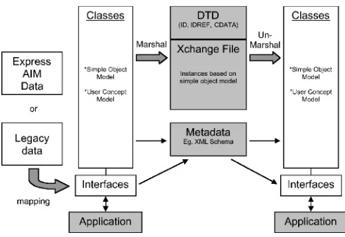
Rando (2001) described the use of an XML mapping of STEP instead of EXPRESS for application-to-application interoperabil-ity. Product data sharing was enabled using object serialization early binding (OSEB). The objective of the standard was to pro-vide a means of serializing (or persistently storing) the state of (ship data) objects contained within an object-oriented database into a neutral format that may be communicated from application to application. One of the benefits of using XML as the informa-tion syntax is the amount of development of parsing, querying, transformation, validation, and presentation tools for the support of the language across all aspects of the information technology industry. Rando argues that the lack of such development and the reliance on special-purpose tools for STEP is one of the main inhibitors for the wide-scale acceptance of STEP technology within small and medium enterprises, a point that is also made by Ross and Garcia (1998). OSEB is also geared toward being able to represent a complex web of a large number of interrelated objects as a series of more manageable chunks corresponding closely to the user’s conceptual model. The technique addresses one of the major shortcomings related to STEP mapped using EXPRESS: the references contained within a STEP-EXPRESS file restrict the deconstruction of the file into more manageable chunks. The OSEB is illustrated within Fig. 4 as a layered architecture. The first layer is an object model that defines the stored product data using either EXPRESS or some other modeling language. The second is described as the object model of the object inter-faces that are presented to applications. The third is the object model that underlies the classes that implement the OSEB “wrap-per.” The last is the object model that underlies the contents of the OSEB file itself.
Finally, Rando states that the objective of the OSEB was to minimize complexity and not the size of the XML files. XML files have an unavoidable concession in that they are not specifically designed with compactness in mind due to the necessary inclusion of tags, for instance, and the lack of a binary format. However, the files are generally more readable and have a more obvious data hierarchy than EXPRESS.
As well as developing standards for the mapping between XML and STEP, the Maritech Evolution of STEP (ESTEP) project (Gischner et al 2001) is continuing the development alongside NIDDESC of the STEP shipbuilding product model standards and data exchange of the Defence Advances Research Projects Agency (DARPA)/Maritech MariSTEP project. It is intended that ESTEP will enable the efficient transfer of data among shipyards, design agents, and regulatory agencies.
Gischner et al state that the current STEP APs take 3 to 5 years to develop, and a great deal of time has been wasted developing similar standards by different industries. Figure 5 illustrates the evolution of STEP from individual APs to a plug and play ap-proach through STEP modules.
Advancements within both the ship design process and the availability of cheap and powerful computational resources were identified as being the main drivers for the explosion in the amount of data contained within the ship product model (Catley
Fig. 3 NIAM diagram of the NE UTRABAS high-level model (Welsh 1992)
Fig. 4 Layered object models in OSEB (Rando 2001)
[image:4.584.297.547.30.202.2] [image:4.584.42.553.516.671.2]1999). Catley states that a modern commercial vessel may be expected to have an associated product data model 2 to 10 gigabytes in size, depending on its complexity. Archiving, ver-sion management, and a robust product information solution are seen as essential requirements for a competitive shipbuilding in-dustry.
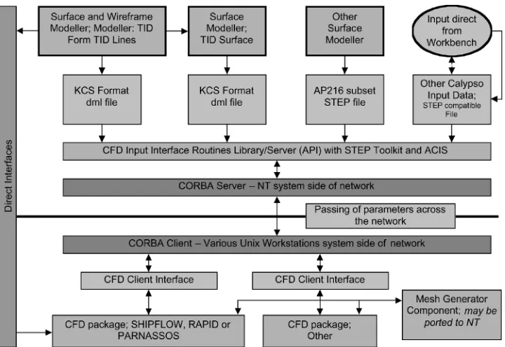
Catley also discusses the translation of the AP215 compartmen-tation and AP216 ship molded forms schemas between the TRIBON system and either SEASPRITE or MariSTEP represen-tations. Despite an increasing demand for the standardization of product information to enable a common-model representation, Catley recognizes the need for openness between specialist sub-contractors and partners in order to achieve common access. Fig-ure 6 demonstrates the data flow between KCS and Calypso.
Crawford et al (1999) defined a geometry object structure (GOBS) as being organizational, to enable the data to be accessed by logical groupings or views; topological, to define the physical relationships between model elements; and representational, as a result of the topology. The resulting structure enabled both topo-logical views (a view of space, not the space itself) and common views (compartments, machinery spaces).
The development of ship product data formats and structures has seen a great deal of focus on the ship STEP APs as well as using EXPRESS and more recently XML as languages to model the data. The ship STEP APs are clearly required to represent large amounts of complex data. However, they also require a concerted and constant effort for finalization to avoid stagnation and to improve general uptake across the industry. These technologies rely heavily on information technology, which is notorious for progressing more quickly than standards are produced. Informa-tion technology consideraInforma-tions are therefore vital in the develop-ment of the data formats and the supporting mechanisms in order to ensure that the standard does actually ensure the exchange of product data. In addition, the operational, maintenance, and
de-commissioning life phases need to be thoroughly supported within these data structures.
Ship product modeling
Martin (1980) was perhaps one of the first people to discuss product information systems within shipbuilding and defined the product model as “a logically-structured, product-oriented data-base.” The product model term was, however, considered by Mar-tin to be a misnomer, because the inclusion of nonproduct infor-mation, specifically information relating to the yard facility, was considered to be one of the most important benefits of the system. The product model was described as consisting of a number of logically complete database subsets that contain overlapping structural and material information for the product (Fig. 7).
Martin realized that the product model was not simply a design tool, but the information contained within it may be utilized by other yard functions to determine material requirements, issue purchase orders, schedule activities, and so forth. Indeed, since the advent of numerically controlled machines, the product model has been viewed as a tool to automate parts of the production process (Johansson 1995, Ross & Garcia 1998, Ross & Abal 2001).
During the early 1990s, Schmidt et al (1990) explored the fol-lowing options for the format for the product modeling and digital data transfer (DDT) within the U.S. Navy’s AEGIS destroyer program:
1. “Flavored” initial graphic exchange specification (IGES) or standard IGES. “Flavoring” is the term used to define the process of augmenting the shortcomings of the implemented standard in order to adapt it to the required task.
2. Deferment until the completion of product definition ex-change standard (PDES) and its commercial implementa-tion.
[image:5.584.113.473.421.669.2]3. Development of direct translators by a software developer specializing in computer-aided design (CAD) direct transla-tors.
4. Use of a neutral file that defines object data.
Option 1 was rejected due to the associated shipyards’ using object- rather than entity-oriented CAD software. PDES was con-sidered to result with a delay of several years to implement a production translator; hence, option 2 was rejected. Flexibility and expansion were considered as restricting factors for option 3. Fi-nally, option 4 was accepted due to the ability to develop a neutral model in the available time, and the flexibility and future expan-sion of such a model.
Schmidt et al also introduced the concept of the “design win-dow” to transfer only the part of the model that was required rather than the entire model by specifying boundaries for the design zone to be transferred. One important aspect related to the transfer of partial data was the requirement for effective configuration man-agement such that changes made to the partial models were re-flected within the overall model. Higney and Ouilette (1994) fol-lowed up the discussion of Schmidt with a description of a STEP-based product model for the AEGIS destroyer. The product model was split into two parts: a graphical model and a relational data-base containing nongraphical data. NIAM diagrams were initially used to define the relationships within the relational database. The model was developed based on the more fully developed STEP piping AP. However, other APs were to be included when they became available.
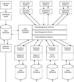
Welsh et al (1992) focussed on the precommissioning life-cycle stages of the shipbuilding product model while developing a framework to integrate disparate computer-based information sys-tems within the ESPRIT II–funded NEUTRABAS project (Fig. 8). The underlying mechanism to achieve this integration was a prod-uct model database to contain and manage neutral shipbuilding data, specifically spatial, structural, integration, outfitting, and en-gineering systems data. It was identified that the structure of the data was as important as the data themselves in order to effectively
manage the exchange of the data across various complex and heterogeneous ship development applications.
Baum and Ramakrishnan (1997) suggested that associativity data are extremely useful additions to the product model because they enable changes made to any one of the objects within the database to be reflected in all associated objects. Baum and Ra-makrishnan, however, did not suggest how this change propaga-tion is managed because without due coordinapropaga-tion the impact of the change may result in chaotic behavior in complex systems (Whitfield et al 2000). Additionally, there is no discussion regard-ing the requirement to simulate the reflected change usregard-ing the simulation software to determine the adequacy of the initial change.
The overall aims of the NEUTRABAS project were defined as:
The standardization of the way in which information con-cerning marine-related products is represented
The development of standard methods for the exchange and storage of product definition data in the marine industry
The specification and development of a suitable database architecture that will facilitate the exchange and storage of such product definition data
The implementation of a prototype data exchange and storage system, based on the previously defined database ar-chitecture, which will demonstrate the feasibility of a truly integrated product life cycle.
The authors identified a number of benefits associated with the above aims, such as the reduction of project time scales through the adoption of a single managed information store. Managing the information within a single database is intended to avoid infor-mation mismatches and hence reduce the amount of rework, which
Fig. 7 Product information system layout (Martin 1980)
[image:6.584.54.264.34.243.2] [image:6.584.297.551.387.669.2]has indeed been reported within a number of publications. How-ever, there has never been any consideration of the database con-trol mechanisms required to prevent the database from becoming an information bottleneck despite the assumption that a benefit would be more effective information management, or the in-creased duration associated with searching a single (extremely) large database for the required piece of data despite the assump-tion that a benefit would be rapid informaassump-tion disseminaassump-tion. There is also the suggestion that using such a representation of product data will avoid the need to transcribe the data between different application systems, eliminating the introduction of error through human interaction. However, a number of papers have since reported on the requirement of application interfaces to translate the product data into a format suitable for the intended application. Indeed, Rando (2001) reported that in some cases a degree of human interaction has been required to ensure that this process runs smoothly. Conversely, Catley (1999) suggested that the minimization of human interaction within the data exchange process has resulted in more consistent design. Finally, the authors identified the benefit associated with improving the interface be-tween the supplier and the client through the introduction of elec-tronic product definition databases.
The NEUTRABAS system was composed of an application-independent EXPRESS model defining the shipbuilding product; a data dictionary to manage requests to the database; a mapping between the model and the dictionary in the form of an EXPRESS import tool; the data management component to enable the cre-ation, communiccre-ation, modificcre-ation, and querying of product model data; a number of application interfaces to enable the in-dividual applications to interact with the database; a number of database interfaces to enable communication between specific da-tabase management systems and the NEUTRABAS dada-tabase; and a database generator that enables the mapping of data within a specific database to the data within the NEUTRABAS database.
Von Haartman et al (1994) described the ship product model within the NAPA project and realized the potential of the product model as a basis for concurrent engineering (CE). The use of computers within the shipbuilding industry was previously re-stricted to the computationally intensive applications, such as the calculation of hydrostatics and stability. These applications have had a great deal of development to produce tools that represent and model a particular characteristic of the design quite accurately. They have generally received a great deal of investment of time and money (Crawford et al 1999). Von Haartman et al suggest that the modern ship design process should ideally consist of a single system that augments all of the disparate design tools but that one should recognize that such a system is far from reality. The alter-native was to provide a framework to interlink these design tools to give the impression of a single system. The ship product model was the key to interlinking these tools.
Von Haartman et al also stated, “Any model merely reflects selected properties of the object it is intended to describe, and the appropriate selection of properties is of central importance when designing the model.” Within the NAPA ship product model, global properties of the ship were identified, such as the main dimensions, hull form, and so forth, and although not explicitly stated, it is assumed that these global properties were chosen partly for the reason that they are common among the design tools being utilized. These properties within the model may also be used to evaluate the economic and technical requirements of the ship.
Finally, Von Haartman et al stated that the lack of detail of the global properties within the ship product model is not synonymous with inaccuracy.
Johansson (1995) described the challenge of modern shipbuild-ing as “to manage and control the design and assembly process to gain efficiency and short delivery times.” By summarizing the shipbuilding process life-cycle stages as tendering, design, pro-duction, planning, materials, finance, and follow-up, the require-ment for the effective managerequire-ment of the extremely large amounts of information was established in order to ensure the efficient organization of the shipbuilding process. Johansson suggested that this requirement could be satisfied only through the development of “an information flow solution specifically designed for this industry” and suggested that it was not sufficient just to automate existing manual activities. Rather, the organization should be adapted to the use of new tools to streamline the information flow wherever possible. The discussion appeared, however, to be re-stricted to information flows within a single shipbuilding organi-zation with the main focus on how the information may be utilized to improve the production process.
The product model concept was regarded by Johansson as being one such tool whereby the organization may be streamlined throughout the precommissioning stages, by providing a consis-tent model to enable well thought-out build strategies to be de-veloped, early ordering of materials and material handling, pre-fabrication, preoutfitting, and the use of numerically controlled machines.
Additional information was contained within the product model, such as material codes, weights, surface treatments, and so forth. For this reason, Johansson suggested that a more appropriate term may be product information model, because the model should contain all technical product definition data and may be used to provide, for example, graphical representations of geom-etry as well as lists and reports of material requirements. Addi-tionally, Johansson stated that the generation of a graphical rep-resentation should be produced only when it is required and to the extent that is suitable in order to avoid unnecessary computation. The graphical representation is regarded as secondary information of the (primary) information stored in the product model. The information flow may be streamlined by the manipulation of the primary information rather than the secondary information.
Johansson also recognized that it was important that “a product model based system must understand what the different parts of the system really represent, and be able to interpret the rules and restrictions connected to each type of object.”
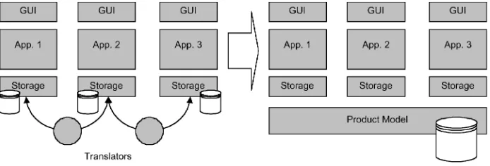
inter-face standard. A common product model (Fig. 9) was imple-mented within ShipX, and from the application development viewpoint, it enabled:
Developers to concentrate more on the specific simulation problem rather than the modeling of the data. This benefit is realized every time a particular application goes through rede-velopment or when new applications are developed.
Guaranteed synchronization of data between the applica-tions and the product model. Translators were previously used to convert the product data to and from the required formats for each application. Changes could potentially be made to the product model after data translation to the application, resulting in a discrepancy in the translated data. The product model technique ensures that each application has a common repre-sentation of the ship.
Reuse of previous applications, and graphical user inter-faces, eliminating the need for the end user to relearn how to use the application.
Despite integrating existing applications with the product model, it is not clear within the ShipX project whether integration existed between applications. For example, two discrete applica-tions may be considered as damage stability assessment and evacuation simulation, both integrated via the product model. It is possible to make assessments of the performance of the ship with respect to both the damage stability and the evacuation in isola-tion, via the integration with the product model. However, inte-gration is required between the damage stability and evacuation applications in order to assess the evacuation time while compart-ments are flooding.
The ShipX product model was developed using the relevant shipbuilding protocols developed within STEP, which were imple-mented into a class library and stored using an object-oriented database.
Erikstad gave a number of useful guidelines for the develop-ment of the ShipX system:
Simplicity. The development of a comprehensive product model tool was considered to be prohibitive both from the aspects of timeliness and cost effectiveness. Wherever pos-sible, commercial off-the-shelf components were used. The development of the actual product model was undertaken using the STEP shipbuilding protocols, rather than developing an in-house product model from scratch.
Flexibility and extensibility. The model was initially lim-ited to representing data that were specific to hydrodynamic performance. However, consideration was given to the struc-ture of the model such that it could be extended to represent other performance aspects. Also, the use of STEP to produce the common product model enables the scope of ShipX to be extended without restructuring the model. The facade design pattern was also used to hide the complexity of the product model from the client applications, define the correct usage of the product model by the client applications, and enable the updating of the product model without affecting the client ap-plications.
Weak bindings to platform and programming language to enable the cross-platform and cross-language integration of the product model.
Baum and Ramakrishnan (1997) regarded three-dimensional product model technology as being fundamental for the imple-mentation of concurrent engineering (CE) within shipbuilding due to the ability to develop, capture, represent, integrate, and coor-dinate data and permit simultaneous access to a number of users. Baum defined the product model as “the integration of the 3D geometric model and non-geometric database information,” which may be a logical integration of distributed information (Fig. 10). Simulation and interaction with the objects within the product model through the introduction of anthropomorphic models into a virtual environment to test functionality and operability were dis-cussed as being a useful technique to test the validity of the model in a way similar to what would be achieved with the final product. The resulting model is essentially an electronic “mock-up.” Baum suggested, therefore, that it is important to also represent the nor-mal behavior of the objects within the ship product model such that their behavior may also be analyzed, enabling the product to be designed, manipulated, analyzed, constructed, tested, operated, supported, and disposed of in a virtual environment.
Ross and Garcia (1998) and Ross and Abal (2001) discussed the utilization of product modeling technologies within two different shipyard applications: new build and conversion with the focus of aiding shipyard managers with the decision to adopt such tech-nologies. Ross suggests that the key characteristic of the product model for achieving a high level of integration is the adoption of a single database, allowing a number of designers to simulta-neously work on the same design through effective database man-agement, and reducing or preventing altogether the inconsistency
[image:8.584.119.466.543.661.2]of information. A number of small shipyards that have incorpo-rated product-modeling technologies are used as case studies to discuss the technique’s effectiveness with the conclusions that these shipyards have an improved production quality and signifi-cant savings in material cost, labor cost, construction cost, and labor hours. Despite being a more complex representation than traditional techniques, Ross and Abal (2001) concluded that staff training was straightforward and that staff were considered com-petent after the design of the first vessel.
Polini and Meland (1997) discussed the extension of a prototype product modeling system through to the development of a pro-duction implementation that was capable of supporting concur-rent, multiuser access. Life-cycle data and behavior were modeled within the classes contained in the Smart Product Modelling (SPM) system. The differentiation between a standard product model and an SPM system is shown in Fig. 11. To appreciate the amount of effort involved in developing the SPM, Polini and Meland state: “To date, nearly 45 man-years of software devel-opment have been invested in the SPM and its GUI; approxi-mately 1000 classes with over 30,000 methods have been devel-oped; object oriented databases on the order of 2.5 gigabytes are commonplace; 24 concurrent users have modeled five ship classes; and tens of thousands of structural parts have been manu-factured.”
This development was undertaken entirely within a shipyard without any commercial input. Polini and Meland justified this development by surveying the requirements of the shipyard and concluding that there were no commercially available systems capable of dealing with the degrees of specialization within the shipbuilding industry, a point that has also been made by Jo-hansson (1995).
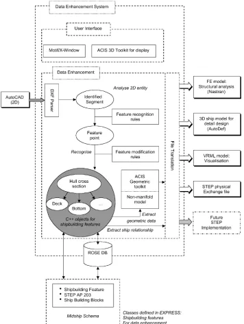
One of the questions asked by Shin and Han (1998) and others (Baum & Ramakrishnan 1997) is whether it is possible to imple-ment paperless design because designers often spend a great deal of time trying to extract useful information from two-dimensional paper drawings. The shipbuilding building blocks within the STEP shipbuilding APs were used as the basis to produce a ship product
model. Shin used the STEP toolkit ST-Developer to produce C++ classes using the EXPRESS data definition language for the mid-ship section of a bulk carrier.
The classes were enhanced to enable all life-cycle product in-formation to be stored within a single data structure as well as for translating data formats by one-to-one mapping, and including explicit information (Young’s modulus, Poisson’s ratio) from de-sign conventions available within the product model. The system architecture can be seen in Fig. 12. This enhancement was re-quired because Shin suggested that it was not sufficient to simply translate data from a neutral format into the format required by each application. Rather, it is a requirement of each application that associated functions and information specific to each appli-cation is also incorporated into the model.
This requirement for functional data was also discussed by Crawford et al (1999). Rather than relying on a flat neutral file to contain geometry and topology information, it was considered useful that the topological data for example were provided with some sort of intelligence to facilitate the translation between ap-plications. The STEP standards were adhered to wherever pos-sible. However, achieving intelligent topology required extension of the standards. Crawford defined the Newport News Shipbuild-ing view of a product model as “an all encompassShipbuild-ing model of a
[image:9.584.118.466.31.240.2]ship project . . . taking advantage of the available computer tools for describing the geometry of a ship, but it also includes all attributes necessary for the design, production, and operation of the ship.”
Again, it was considered unlikely that the ship could be defined by a single computer system, rather than by a number of more manageable systems grouped according to some arbitrarily de-fined domains (Fig. 13).
Crawford demonstrated the use of intelligent topological and geometric STEP-based data through the use of the GOBS common object request brokerage architecture (CORBA) server that pro-vides a number of methods to enable legacy tools to extract the required data. Two analysis tools were used to model the ship:
vulnerability and hydrostatics, which obtained their data from the GOBS server. The analysis concluded that within the majority of the cases, the STEP standard for geometric data (Part 42) was sufficient to represent the geometry for the ship.
Rando and Fernholz (2000) describes how the DARPA Mar-itech Shipbuilding Information Infrastructure Project (SHIIP) and Shipbuilding Partners and Suppliers (SPARS) projects used a combination of component-based software, internet protocols, and a portable computing platform to satisfy the following shipbuild-ing information technical requirements:
[image:10.584.115.471.33.506.2] An information technology gap separates the large, me-dium, and small shipyards.
The information technology staffs at most shipyards are experts in shipbuilding process requirements but not in system-level computer technologies.
Shipyard information systems must be reliable and main-tainable yet often need to be customized to suit an individual shipyard.
As with many other projects (Rando 2001, Gischner et al 2001), integration within the shipbuilding industry was considered pos-sible only by the reuse of existing software components because the number of shipbuilding system requirements is so diverse that it is unrealistic to assume that it is possible to produce a single overarching solution. The integrated system was considered to consist of a number of independent components to be assembled and reused by third parties in order to create a new complex system. The initial task of the SHIIP project was to define a reference architecture to support the composition of the indepen-dent components.
The management of the product data was achieved using En-terprise Java Beans (EJB) that enable persistent storage, secure access, and load balancing for multiple users wishing to access the data simultaneously. At the start of the SHIIP project, however,
EJB was not available, and the project relied instead on CORBA technology. The project learned the following lessons from using CORBA:
Technology independence, although useful in theory, should not be pursued at the expense of developing working implementations.
Technical interoperability is not a requirement for the de-velopment of an industrial information infrastructure. Support-ing applications and software components for the information infrastructure are homogeneous enough to be implemented in a single implementation technology.
The Object Management Group (OMG), while advocating separation of components, has produced, in the arena of do-main standards, wrappers for monolithic applications.
OMG has been hampered by the inability to reach timely consensus.
The Integrated Shipbuilding Environment (ISE) project within the Maritech Advanced Shipbuilding Enterprise (ASE) is using XML as the basis for achieving interoperability between ship-building systems technologies, specifically between application to application (Rando 2001). Rando differentiates this problem from that of other industries by stating that many of the application components used within the shipbuilding industry have already been developed as well as the having little control over the de-velopment of these systems. The shipbuilding product model may also contain millions of instances of a large number of different types of information that need to be managed as they evolve over the product’s life cycle. It is also suggested that not only is there a need to rely on an enterprise system that augments the many specialist applications, but due to the diversity of information within the life cycle of the ship, no single information system is sufficient to deal with the entire ship product. Indeed, previous alliances between shipyards have been one-off solutions, and there is a definite requirement for a standardized effort for the ship product model.
Rando identified a number of business drivers in order to achieve interoperability within the shipbuilding industry and
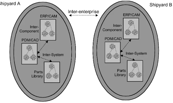
[image:11.584.38.285.35.178.2]pro-Fig. 13 Domain-based ship system (Crawford et al 1999)
[image:11.584.127.463.472.672.2]posed an architecture in order to respond to these drivers (Fig. 14). The architecture represents three interoperability levels within the shipbuilding environment: intercomponent refers to the interac-tions between the software components within a system, intersys-tem refers to the interactions between the sysintersys-tems and is bounded by a business system domain, and interenterprise interoperability refers to interactions between business systems domains at differ-ent shipyards and organizations.
The key elements for achieving this interoperability were a common syntax using XML to facilitate communication, a shared standard information model using STEP, and an interoperability infrastructure using web-based technologies. XML is a neutral format that may be viewed by humans (although this is not gen-erally a primary requirement) and that enables the sharing of in-formation between different technologies, different operating sys-tems, and, different programming langua ges. Five key requirements were identified to facilitate application-to-application integration:
Should “reuse” widely available, standards-based tools Should be implementable with tools that allow for recon-figuration by nonprogrammers
Should support transformation to and from a canonical or neutral format
Should utilize a representation that is as simple and con-cise as possible
Should be able to marshal/unmarshal every semantic con-cept representable in the EXPRESS information modeling lan-guage (ISO 10303-11).
One of the most significant issues relating to the use and inte-gration of ship product models with existing applications appears to be the need to “flavor” the model and specifications to suit the particular requirements of the design and simulation applications. Without these embellishments, the fully automated data integra-tion appears quite often difficult to achieve. There are, however, conflicting opinions regarding the effectiveness of automating this process generally arising due to the complexity of the problem and the level of support. The application of “flavored” standards does, however, entirely go against the point of creating a standard, es-pecially when it is with respect to the transfer of product data. It could therefore be concluded that the solution to the effective integration of STEP lies not in the modification of a new tech-nology to satisfy the requirements of legacy applications, but in the updating of the legacy applications to satisfy the new technol-ogy.
Life-cycle issues
The NEUTRABAS project (Welsh et al 1992) was limited to the precommissioning stages, that is, marketing, conceptual de-sign, detailed dede-sign, drafting, materials ordering, production planning and control, scheduling, and quality control. However, it was recognized that significant benefits would be achieved through extending the life cycle through to disposal. Welsh et al qualified the limitation to the precommissioning stages by stating that “the definition and implementation of a complete product data model covering all of these aspects of the life-cycle of an engi-neering product as complex as a ship is an onerous task, and one
which would require the commitment of a vast amount of time and effort.”
Limiting the project to the precommissioning stages would ap-pear to have been a wise judgment because in the 10 years fol-lowing this project, the standards created to describe the ship product model have still not yet been finalized.
Welsh et al suggest that the physical representation of the prod-uct within each life cycle stage would “normally be unchanged in the global sense, although the information associated with the product and the techniques used to represent it will vary consid-erably,” that is, the information contained within the product model would mature as more detail becomes available, as well as requiring different viewpoints at each life-cycle stage. The product model must therefore be developed not only with the associated data and structure in mind, but also with the life-cycle stages. To enable the support of the precommissioning life-cycle stages, Welsh et al identified four views that need to be supported by the ship product model:
Marketing-oriented view Management-oriented view Design-oriented view Production-oriented view.
Von Haartman et al (1994) briefly discussed life phase issues of the ship product model and suggested that a number of systems model the design with too much detail, and hence are not appli-cable to the concept design stage. A solution to this was the development of a concept design product model that could then be transferred to the detailed design stage. It is not clear from this whether Von Haartman et al were proposing separate models for the two stages or if the detail product model would simply consist of the concept product model plus the additional required detail. The mechanism of having multiple different views for the shar-ing of a product model among designers and production engineers, for example, has been considered and implemented in a number of cases (Polini & Meland 1997, Johansson 1995). Johansson indi-cated that it is common for parts of the product to be in different life-cycle stages at the same time, that is, the “manufacture of one part of the product is going on at the same time as the detailed design of another.” This is one aspect of concurrent engineering with the result of reducing the lead times because the manufacture of the product has started before the design of the product has been completed. However, it is necessary to ensure both that manufac-turing starts only on parts that require no further design and that other parts that are currently being designed do not propagate changes to the manufactured parts. The management and control of the information flow were recognized as being the key elements in increasing the overlapping of life cycles. However, no expla-nation was given by Johansson regarding the nature of the man-agement other than through the relationships between the objects contained within the model. These relationships were described as a mechanism to enable both interdisciplinary and cross-disciplinary communication among designers.
Coupled with simulation-based design (SBD), Baum described the combined technology as “the new frontier” that would enable the virtual prototyping of the ship, which previously could not be achieved due to the cost and complexity. More importantly, Baum recognized that just as interference-checking software may be used to determine discrepancies between geometric parts during the design and production phases, SBD may be used to reduce or eliminate design errors that would have previously have been discovered years later in the operational stage, for example. Es-sentially, SBD and product modeling enable the validation of the design, production, and operation stages of the ship product.
Baum also finally suggested that the product model provides a significant benefit to the owner/operator by enabling the analysis and support of life-cycle maintenance.
A generic shipyard computer modeling tool for evaluating de-sign for production (DFP) is discussed by Lamb et al (2000). The tool enables shipyards to be modeled such that the impacts of changes to the ship design may be determined on the basis of the resulting material, manpower, and schedule. The shipyard model represents details of the buildings—their arrangement and size, as well as equipment, capacity, and flow. The tool also enables an investigation of the necessary changes required for a shipyard in order to produce a new design. The key foundations in order to evaluate these impacts are the interim product catalogue and the build strategy approach.
Lamb et al identified a number of important concepts for DFP:
All designs should be prepared to suit a shipyard’s facili-ties and preferred production methods.
DFP takes into account production methods and tech-niques that reduce the product work content but still meet the specified design requirements and quality.
DFP must be incorporated into a design from the start. Traditional engineering leaves it up to another department, such as production or manufacturing engineering, to develop the technical documentation required for the production work-ers. This is an unnecessary duplication of effort and is a non– value-added task that takes time.
An objective of the CE approach is to accommodate DFP by bringing all the necessary people together right from day one on a project.
The time to influence the cost of a product is during the early stages. After the design has been developed in concept, most of the opportunity to positively affect cost is gone.
World-class ship designers know how their shipyard builds ships and design accordingly. Many ship designers do not consider this, and the designs may or may not be efficiently built in their facilities. More shipbuilders have taken steps to remedy this situation through the use of the build strategy approach.
Engineering should be prepared and transmitted to the users in a way that best suits block construction, advanced and zone outfitting.
An object-oriented approach was adopted for the construction of the model (Fig. 16). The model represents shipyards, worksta-tions, products, equipment, processes, manufacturing processes, material handling processes, and interim products. The tool was applied to the evaluation of two design alternatives for the bottom structure of a ship. The authors demonstrated that the tool enabled reliable evaluations of the man-hours for manufacturing and ma-terial handling such that the best design alternative could be adopted.
Future directions
It is believed that the ship STEP APs will become the standard unit of shipbuilding data but that it will probably be an evolution-ary process as advances in technology and modeling capabilities and requirements are incorporated. It is, however, crucial that the development of the standards comes to a timely consensus at each evolutionary stage. The literature reviewed has discussed the use of “intelligent” data, the inclusion of useful functionality accord-ing to the data type, and of behavioral aspects. It is anticipated that this functionality, behavioral aspects, and so forth will
[image:13.584.112.473.49.237.2]ingly become part of the model to the extent that the model no longer has any need for interfaces and translators to legacy soft-ware. For example, the piping model would automatically calcu-late interferences, and the structures model would automatically calculate stress characteristics. The simulation would essentially be part of the model and the model would contain additional information and knowledge to effectively manage the simulation. This is not to say that the model would become a monolithic system, despite such a system being potentially computationally viable in 10 years. Rather than being monolithic, current and future distributed information technologies, such as Enterprise Java Beans, may be utilized in order to distribute the model across a network while giving the impression to the user that the system is monolithic. Ship product data and functionality would be dis-tributed either within a single company or as partnerships with other companies.
In a similar way that the ship product data has become stan-dardized, benefits are to be gained from standardizing the inter-faces between applications to support the flow of standardized data and achieve a truly seamless integration. The unfortunate shortcoming of application standardization is the necessity to re-develop the legacy systems to support this level of integration.
The VRShips project addresses the management of ship product data within a neutrally formatted common model. The geometry
data contained within the common model are based on STEP AP203, are described using XML, and are considered as being common data if two or more applications access it. Integration is provided between the legacy applications and the common model via “generic wrappers” that provide the general management re-quired in order to operate the applications. The wrappers convert the data to and from the native format using modular conversion algorithms that can be plugged into the wrappers and provide the domain-specific management for the applications. Data are auto-matically downloaded from the common model and converted into the native format when the application is started. When the appli-cation is complete, the designer has the option of undertaking the reverse process to convert the data back into the neutral format and upload into the common model. Despite being a complex process, converters have been produced for a number of design applica-tions, such as Tribon and AVPro, and have been demonstrated to operate without the need for manual interaction. However, the issues relating to the lack of integration between tools and con-tinuous product models remain to be addressed.
[image:14.584.80.504.32.384.2]The VRShips system also has an additional management layer consisting of a process controller and an inference engine that are jointly responsible for maintaining data consistency; and version, constraint, and process management. Visualizing of product data via the legacy applications is managed through the exporting of
the displays via a virtual interaction environment. These control mechanisms ensure that designers may modify the data contained within the common model from any location either organization-ally or geographicorganization-ally distributed with network access using an application that they are familiar with, and that any changes made to the product model are correctly propagated such that the data remain consistent.
Every product modeling tool and technique discussed within this review is common from the perspective that the data contained within the model are a “snapshot” of the actual design activity. For instance, a designer may download data from the ship product model for use within a general design package, which may take a week to design. During this design period, the data within the product model do not change until the designer decides that the design process is complete and the data are uploaded into the product model. The product model therefore does not contain a continuous representation of either the design work that is cur-rently being undertaken or the form that the data are in. This poses a number of significant project management issues with respect to version control, consistency management, and conflict resolution, especially in the situation where the design process is being un-dertaken in a distributed manner, as is increasingly becoming common.
A paradigm shift in the techniques used to enable the distributed design of ships while enabling a continuous product model and facilitating the management of conflicts and consistency would be the adoption of a technology that is more often seen within the computer games industry. Graphics servers are commonly used within the games industry to enable the user to immerse them-selves within an environment and interact both with the environ-ment and with other users. High-level graphical objects are com-municated between the server side and the client side rather than using structured files. This technique bypasses the need to trans-late the communicated data into the client side format, alleviating unnecessary computation. It also results in a model contained within the server and represented within the clients that is a con-tinuous depiction of what everyone is undertaking. The ship prod-uct data would remain within the ship STEP formats. However, the description method would be the graphical object representa-tion that would also exhibit behavioral properties. Within the ship-building context, individual graphics servers would represent do-mains similar to those identified by Crawford et al (1999). Clients connecting to the servers would immediately get an up-to-date view of that particular domain, which would be consistent with the views of all of the other clients. The client software would operate in a manner similar to conventional design applications. There is also clearly a requirement for integration between the different domain servers to enable conflicts to be resolved across domains. Simulation servers would integrate all of the scenarios that would enable an evaluation of the performance within any particular life phase. There would still remain the need to provide an effective management of different versions, as well as a high-level coordi-nation structure to manage conflicts, constraints, design goals, and collaboration among designers. However, the underlying frame-work would provide the basis on which to construct this. Despite being a significant step-change compared with current practice, this future technique proposes a viable solution to the effective management of a ship product model that may be manipulated and operated upon in a distributed manner.
This type of architecture does, however, raise a number of
issues relating to partnerships between the shipbuilding industry and the shipbuilding software industry, because the system would represent an amalgamation of existing design and simulation ap-plications into a number of domain-specific servers. The intellec-tual property rights as well as the ownership of both the technol-ogy and the data contained would clearly need to be resolved. In addition, the system calls upon the need to implement a standard for the communication of the graphical objects that is both secure and robust, whereas the standard for the data may be “flavored” and managed effectively within the system via the ability to dy-namically load classes.
Just as many of the precommissioning life phases are currently being modeled, it is anticipated that the rather poorly supported postcommissioning life phases will be catered for. The most sig-nificant difference between pre- and postcommissioning is that it will be the ship product model in its entirety that will be consid-ered. For example, there currently appears to be a significant opportunity for the specialization of the immersion of an entire ship product model into an artificial environment to determine the operational performance both at virtual sea (modeling existing shipping lanes to determine sea-keeping characteristics), within a virtual port (modeling existing ports to determine cargo-handling characteristics), within a virtual shipyard for recommissioning (modeling existing shipyards to determine recommissioning capa-bility), and within a virtual breakers yard for disposal (to deter-mine scrap value). Increased opportunity would therefore be made for designing the ship to meet a more rigorous set of customer-specified life-phase requirements and would represent a signifi-cant commercial advantage.
It is also interesting at this point to note that a number of the cited papers have stated the need to avoid a reliance on computer programmers, which in order to maintain even the simplest of product data modeling systems seems unachievable.
Conclusions
From the increasing amount of literature and the papers re-viewed within this paper related to the ship product model, the primary focus is on developing a standard representation for the data contained within the model. Despite not having yet finalized the standards for all aspects of the ship, the STEP APs go a long way toward achieving this. It is almost inconceivable to consider that an alternative could compete against such a massive thrust toward ship data standardization. A number of instances have arisen, however, when the APs have been adhered to, with the result that “flavors” or minor changes to the standard have been required in order to utilize the structured, well-defined, and stan-dardized data within the legacy applications. The question there-fore arises as to whether there is a requirement to standardize the legacy applications such that they adhere to the data standard to enable a modular plug-in approach to ship design and simulation. Behavioral aspects have been considered within a number of the cited papers to be an important addition to the data in order to provide the designer with additional feedback with respect to the operation of the design. This behavior may, however, be better represented as high-level rules within a standard that are used to define the operation of the ship, rather than in existing standards, in order to minimize its impact on applications that have no need for such data.
the use of the ship STEP formats as being a mechanism for inte-grating existing legacy applications with a common model of ship product data. Considerable benefit would be obtained from pro-viding similar integration between applications to progress from the limitations of discrete design and simulation toward having a holistic approach.
The design tasks that are undertaken as part of the ship design process may well take a considerable amount of time and would conventionally result in “snapshots” of the design artifact coin-ciding with the designer uploading data into the common model. A number of future directions have been discussed, which would individually require considerable development in order to imple-ment but which represent possible solutions to issues relating to:
Continuous rather than “snapshot” ship product models Integration between the ship product model and the design and simulation applications, as well as across applications
Removal of information translation problems through the use of high-level graphical objects that are consistent between servers and applications.
A collaborative framework on which to develop version, conflict, and consistency management.
Acknowledgments
The review was undertaken as part of an investigation into common model techniques within the VRShips-ROPAX2000 project. The authors gratefully acknowledge the support given by the European Commission Community Research 5th Framework program under the area of Competitive and Sustainable Growth, which provided the grant (G3RD-CT-2001-00506) that enabled this work to be undertaken.
References
BAUM, S. J.,ANDRAMAKRISHNAN, R. 1997 Applying 3D product modeling
technology in shipbuilding,Marine Technology,34, 1, 56–65.
CATLEY, D. 1999 Prototype STEP data exchanges in ship initial design and
provision of an application programmer interface to TRIBON,Proceedings, 10th International Conference on Computer Applications in Shipbuilding, June, Cambridge, MA.
CRAWFORD, A. K., HARRINGTON, G., AMES, R. M.,AND VAN ESELTINE, R.
T. 1999 Neutral format data exchanges between ship product models and analysis interfaces,Proceedings, 10th International Conference on Com-puter Applications in Shipbuilding, June, Cambridge, MA.
ERIKSTAD, S. O.,ANDFATHI, D. E. 1999 Applying the STEP shipbuilding
protocols as a basis for integrating existing in-house ship design applica-tions,Proceedings, 10th International Conference on Computer Applica-tions in Shipbuilding, June, Cambridge, MA.
GI SC H N ER, B., KA S S EL, B., LA ZO, P., WO O D, R., A ND WY M A N,
J. 2001 Evolution of STEP (ESTEP): exchange of shipbuilding product model data,JOURNAL OFSHIPPRODUCTION,17, 3, 151–160.
GRAU, M.,ANDKOCH, T. 1999 Applying STEP technology to shipbuilding,
Proceedings,10th International Conference on Computer Applications in Shipbuilding, June, Cambridge, MA.
HERZOG, E.,ANDTÖRNE, A. 1999 A seed for a STEP application protocol
for systems engineering,Proceedings, 12th International Conference and Workshop on the Engineering of Computer Based Systems, Institute of Electrical and Electronics Engineers Press, Piscataway, NJ, 174–180. HIGNEY, J. T., AND OUILETTE, J. J. 1994 An engineering product model
based on STEP protocols, JOURNAL OFSHIPPRODUCTION,10, 4, 281–286. ISO. 1996Product Data Representation and Exchange, Part 218: Ship
Struc-tures, International Standards Organization, Hamburg, Germany. JOHANSSON, K. 1995 The product model as a central information source in
a shipbuilding environment,Proceedings, National Shipbuilding Research Program, 1995 Ship Production Symposium, June, Seattle, WA.
LAMB, T., CHUNG, H.,ANDSHIN, J. G. 2000 A generic shipyard computer model: a tool for design for production,Proceedings, 7th IMDC, November, Kyung-Ju, Korea.
MARTIN, D. J. 1980 The shipyard product information system as an aid to
implementing more productive strategies,Proceedings,Research and Engi-neering for Automation and Productivity in Shipbuilding, IIT Research In-stitute, October, Chicago, IL, 81–101.
POLINI, M. A.,ANDMELAND, K. E. 1997 The development and implemen-tation of a SMART product model for ship structure,Proceedings, 9th International Conference on Computer Applications in Shipbuilding, Octo-ber, Yokohama, Japan.
RANDO, T. C.,ANDFERNHOLZ, D. 2000 MARITECH’s shipbuilding
infor-mation infrastructure, JOURNAL OFSHIPPRODUCTION,16, 2, 110–120. RANDO, T. C. 2001 XML-based interoperability in the integrated
shipbuild-ing environment (ISE), JOURNAL OFSHIPPRODUCTION,17, 2, 69–75.
ROSS, J. M.,AND GARCIA, L. 1998 Making the jump to product model
technology, JOURNAL OFSHIPPRODUCTION,14, 1, 15–26.
ROSS, J. M.,ANDABAL, D. 2001 Practical use of 3D product modeling in the small shipyard,JOURNAL OFSHIPPRODUCTION,17, 1, 27–34.
SCHMIDT, W. R., VANDER, J. R.,ANDSHIELDS, V. R. 1990 Modelling and
transfer of product model digital data for the DDG 51 class destroyer pro-gram,Proceedings, National Shipbuilding Research Program, 1990 Ship Production Symposium, August, Milwaukee, WI.
SHIN, Y., AND HAN, S. H. 1998 Data enhancement for sharing of ship
design models,Computer-Aided Design,30, 12, 931–941.
VONHAARTMAN, J., KUUTTI, I.,ANDSCHAUMAN, C. 1994 Improving design
productivity with a product model for initial ship design,Proceedings, 8th International Conference on Computer Applications in Shipbuilding, Sep-tember, Bremen, Germany.
WELSH, M., LYNCH, J.,ANDBRUN, B. 1992 A data model for integration of
the precommissioning life-cycle stages of the shipbuilding product, JOURNAL OFSHIPPRODUCTION,8, 4, 220–234.
WH ITF IELD, R. I., COATE S, G., DU FFY, A. H. B., A N D HILLS,
W. 2000 Coordination approaches and systems—part I: a strategic per-spective,Research in Engineering Design,12, 73–89.
WY M A N, J., WOOL EY, D., GIS CH N ER, B., A N D HO WELL, J. 1997 Development of STEP ship model database and translators for data exchange between shipyards, JOURNAL OF SHIPPRODUCTION,13, 2,
111–124.
Internet addresses
European Marine STEP Association, http://emsa.germanlloyd. org/
ISO STEP ship team, http://www.nsnet.com/NIDDESC/ t23.html
Japan Marine Standards Association, http://www.jecals. jipdec.or.jp/