Int. J. Electrochem. Sci., 14 (2019) 2208 – 2215, doi: 10.20964/2019.03.60
International Journal of
ELECTROCHEMICAL
SCIENCE
www.electrochemsci.orgShort Communication
Effects of Graphite Particle Size on Microstructure and
Properties of In-situ Ti-V Carbides Reinforced Fe-based Laser
Cladding Layers
Hui Zhang1,2,*, Dongting Wu3, Tao Luan1 , Guangchun Xiao2, Wei Zhao2,
1 School of energy and power engineering, Shandong University, Jinan, China
2 College of mechanical and automotive engineering, Qilu University of Technology (Shandong
Academy of Sciences), Jinan, China
3 School of materials science and engineering, Shandong University, Jinan, China *E-mail: [email protected]
Received: 4 November 2018 / Accepted: 22 December 2018 / Published: 7 February 2019
The effects of graphite particle size on the microstructure, hardness and corrosion resistance of in-situ TiC-VC reinforced Fe-based laser cladding layers were studied. Results indicated that the corrosion resistance of the TiC-VC/Fe laser cladding layers could be improved by optimizing the graphite powder particle size. As the graphite particle size decreased from 180-270 μm to 1.3 μm, the average particle size of carbide decreased from 1.73 to 0.46 μm and the microstructure transformed from plate martensite into lath martensite, and finally into granular bainite. The hardness of the cladding layers decreased about 130 HV0.2, but the corrosion resistance increased. The cladding layer prepared with a graphite
particle size of 1.3 μm showed the best corrosion resistance, which was about 3.80 times greater than that of the cladding layer prepared with a graphite size of 180-270 μm.
Keywords: graphite particle size; corrosion resistance; laser cladding; TiC-VC
1. INTRODUCTION
As a surface strengthening and repairing technology, laser cladding can significantly improve the abrasion, corrosion and oxidation resistance of a substrate[1-3], enabling specific performance requirements to be met and reducing the amount of alloy element required [4, 5]. Fe-based alloy powders are cheaper but have poor corrosion resistance compared to Ni-based and Co-based laser cladding layers. Theoretical and experimental studies have been conducted with the aim of improving the corrosion resistance of Fe-based cladding layers. Previous studies [6-9] have optimized the composition of alloy powders by adding moderate amounts of Cr, CeO2 or La2O3 to increase the corrosion resistance of the
cladding layers. Deschuyteneer et al.[10] reported that there was a significant advantage in using smaller particles to improve the wear resistance of NiCrBSi/WC laser cladding coatings under sliding conditions. Boisselier et al.[11] indicated that the smaller the particle size of 316L stainless steel powder, the finer the microstructure of the cladding layer. Tanigawa et al. [12] found that the heat-affected zone decreased with decreasing alloy powder size. It was also found that the corrosion resistance of (TiC-VC)P/Fe laser
cladding layers could be improved by simultaneously optimizing the four initial powders [13]. However, it has not been reported whether the corrosion resistance of in-situ Ti-V carbide reinforced Fe-based cladding layers can be improved just by optimizing the size of the graphite particles. Therefore, the aim of this study was to determine the effects of the graphite particle size on the microstructures, carbide size and corrosion resistance of (TiC-VC)P/Fe laser cladding layers.
2. EXPERIMENTAL PROCEDURES
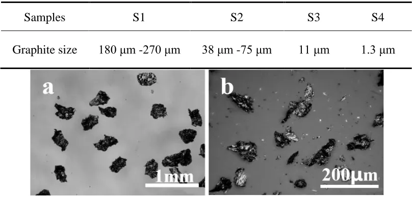
[image:2.596.96.500.577.771.2]Low-carbon steel with dimensions of 80 × 50 × 8 mm was used as the substrate material. The surface was ground using abrasive paper and degreased with anhydrous ethanol before laser cladding. Fe-based alloy powder was composed of 26.00 wt% FeTi30, 16.57 wt% FeV50, 6.23 wt% graphite (purity 99.50%) and 51.20 wt.% iron powder (purity 98.50%). In the molten pool, titanium and vanadium combined with carbon and the Ti-V carbides separated out as the temperature decreased. The particle size of FeTi30, FeV50 and pure iron powder was 38 -75 μm, the variations of the graphite powder particle size are listed in Table 1 and the morphologies of the graphite powders used are shown in Fig.1. Alloy powders were mixed uniformly using a V-series mixing machine. Mixed powders were pre-placed onto the specimen surface homogeneously using sodium silicate binder with a thickness of about 1.0 mm. Laser cladding was performed by a LASERLINE LDF-4000 semiconductor laser; the laser power was 2050 W, the laser beam diameter was 4.0 mm, the scanning speed was 5.0 mm/s and the overlapping ratio was 25%.
Table 1. Initial graphite powder particle size used in S1-S4 cladding layers
Samples S1 S2 S3 S4
Figure 1. Morphologies of the graphite powders used in (a) S1 (b) S2 (c) S3 (d) S4 cladding layers
The phases of the layers were analyzed by the X-ray diffraction (XRD) with a Rigaku RINT-2000 diffractometer (using Cu Kα) set to a working voltage and current of 40 kV and 150 mA, respectively. The step speed was 8°/min. The cladding layers were etched with 4% nitric acid alcohol solution, and the microstructures were observed using a Zeiss SUPRA55 scanning electron microscope. Microhardness measurements were performed with a load of 200 g applied for 15 s. Electrochemical properties were investigated using the potentiodynamic polarization in 3.5 wt.% NaCl solution which were conducted by using a Gamary electrochemical workstation. A saturated calomel electrode, a platinum electrode, and the treated laser cladding specimens were used as the reference electrode, the counter electrode and the working electrodes respectively. Before potentiodynamic polarization tests, the samples were immersed into the electrolyte for about 30 min in order to stabilize the open-circuit potential. The potentiodynamic polarization tests were conducted at a scan rate of 0.5 mV/s. Corrosion morphologies after running the polarization tests were observed by SEM.
3. RESULTS AND DISCUSSION
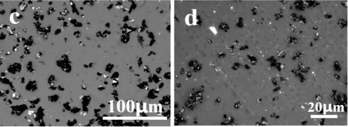
[image:3.596.128.471.71.196.2]Figure 2. Secondary electron images of (a) S1 (b) S2 (c) S3 (d) S4 cladding layers
XRD patterns of the cladding layers are shown in Fig.3. Phase analysis suggested that there was α-Fe, VCand TiC in all cladding layers. Furthermore, the relative intensity of the γ diffraction peaks in S1 to S3 decreased gradually and disappeared completely in the S4 cladding layer, indicating that the amount of retained austenite decreased with decreasing graphite particle size. Due to the decrease in chemical stability caused by carbon and the mechanical stabilization caused by formation of plate martensite, the amount of retained austenite decreased gradually and disappeared. Zou et al.[7] reported that the amount of retained austenite increased, which was caused by the increased chemical and mechanical stabilization in Fe-based composite laser cladding layers.
[image:4.596.181.418.543.737.2]
In addition, it can also be seen that the particle size of in-situ carbides decreased as the graphite particle size decreased from 180-270 μm to 1.3 μm. Fig.4 shows that the average particle size of carbide in S1, S2, S3 and S4 was 1.73 μm, 0.85 μm, 0.68 μm and 0.46 μm, respectively. The greater the uniformity of the graphite distribution and the lower the carbon content, the greater the degree of carbide nucleation supercooling, which further increased the carbide nucleation rate. As a result, the carbide was gradually refined. Masanta et al. [16] indicated that the smaller the initial powder size of TiO2 in the
precursor, the smaller the synthesized TiB2-TiC-Al2O3 ceramic particles, resulting in coatings with
[image:5.596.177.419.225.409.2]superior mechanical properties.
Figure 4. Average particle size of carbides in S1-S4 cladding layers
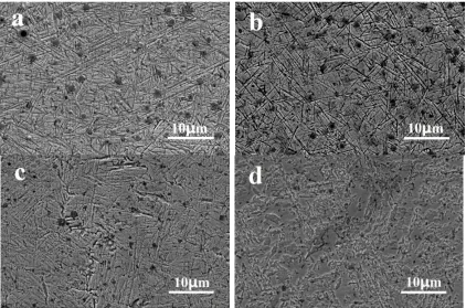
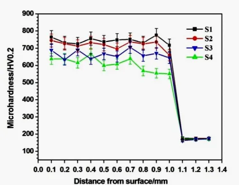
Figure 5. Microhardness distribution curves on the cross section in S1-S4 cladding layers
Microhardness distribution curves on cross sections of cladding layers are shown in Fig.5. The average hardness of S1, S2, S3 and S4 was 744 HV0.2, 719 HV0.2, 665 HV0.2 and 607 HV0.2, respectively,
[image:5.596.177.422.452.642.2]softness of S3 and S4 was due to the transformation of the microstructure.
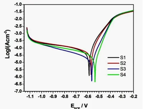
Fig.6 shows the potentiodynamic polarization curves of cladding layers in 3.5 wt% NaCl solution. The fitting results, obtained with the Tafel method, are shown in Table 2 where I0 is the
corrosion current density and E0 is the corrosion potential. The corrosion potential shifted positively
from S1 to S4, and the corrosion rate suggested that the general trend in corrosion resistance was a gradual increase. Because of the different corrosion potentials, galvanic corrosion between the cladding layer matrix (the anode) and the carbide (the cathode) was generated. In previous studies [13], corrosion morphologies showed there to be many pronounced corrosion marks around large carbides, which were accelerated by galvanic corrosion. As the carbide particle size decreased across S1-S4, the cathode area in a single corrosion cell decreased, reducing the total galvanic corrosion and improving corrosion resistance. Overall, the corrosion resistance of the cladding layer was negatively correlated with the carbide particle size, within a specific range.
[image:6.596.176.426.295.486.2]Figure 6. Polarization curves of S1-S4 cladding layers in 3.5 wt.% NaCl solution
Table 2. Fitting results of the polarization curves
Samples I0/(μA/cm2) E0/V Corrosion rate/(mm·a-1)
S1 55.74 -0.59 0.65
S2 51.74 -0.57 0.60
S3 18.16 -0.56 0.21
S4 14.67 -0.53 0.17
[image:6.596.99.501.575.700.2]
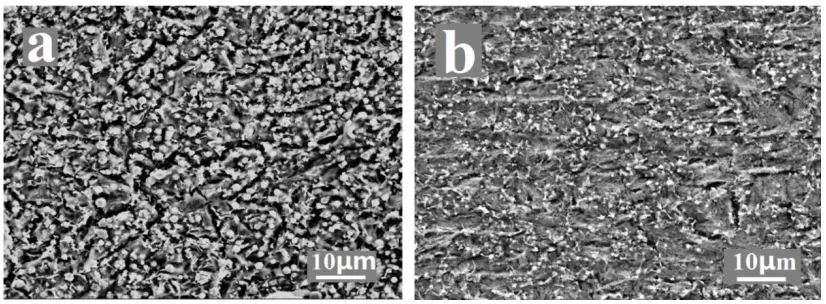
cladding coating was relatively smooth with a small number of long-strip corrosion pits, which indicated that the corrosion behavior primarily occurred at the grain boundaries in the cladding layer matrix. Therefore, galvanic corrosion was the main type of corrosion in the cladding layers, regardless of the size of the carbides.
Figure 7. Corrosion morphologies after running potentiodynamic polarization test (a) S2 and (b) S4 cladding layer
4. CONCLUSION
The microstructure of TiC-VC/Fe laser cladding layers transformed from plate martensite into lath martensite, and finally granular bainite as the graphite particle size decreased from 180-270 μm to 1.3 μm. The particle size of in-situ carbide decreased gradually. The hardness of the cladding layer decreased gradually with decreasing graphite particle size and the general trend was increased corrosion resistance. The cladding layer prepared with a graphite particle size of 1.3 μm showed the greatest corrosion resistance.
ACKNOWLEDGEMENT
The work was supported by the National Natural Science Foundation of China (No. 51605237), the Project Funded by China Postdoctoral Science Foundation (2018M630775), the Key Research Project of Shandong Province (2017GGX30136, 2018GGX103031).
References
1. B. Du, S.R. Paital, N.B. Dahotre, Opt. Laser. Technol., 45 (2013) 647-653.
2. T.E. Abioye, D.G. McCartney, A.T. Clare, J. Mater. Process. Technol., 217 (2015) 232-240. 3. J. Li, C. Chen, T. Squartini, Q. He, Appl. Surf. Sci., 257 (2010) 1550-1555.
4. Z. Zhang, T. Yu, R. Kovacevic, Appl. Surf. Sci., 410 (2017) 225-240.
5. X.-B. Liu, X.-J. Meng, H.-Q. Liu, G.-L. Shi, S.-H. Wu, C.-F. Sun, M.-D. Wang, L.-H. Qi, Mater. Des., 55 (2014) 404-409
[image:7.596.93.506.170.322.2]8. G.M. Zhao, K.L. Wang, Corros. Sci., 48 (2006) 273-284.
9. H. Zhang, Y. Zou, Z. Zou, D. Wu, J. Alloys. Compd., 622 (2015) 62-68.
10. D. Deschuyteneer, F. Petit, M. Gonon, F. Cambier, Sur. Coat. Technol., 311 (2017) 365-373. 11. D. Boisselier, S. Sankaré, Phys. Procedia., 39 (2012) 455-463.
12. D. Tanigawa, N. Abe, M. Tsukamoto, Y. Hayashi, H. Yamazaki, Y. Tatsumi, M. Yoneyama, Opt. Lasers. Eng., 101 (2018) 23-27.
13. K. Chong, H. Zhang, G. Xiao, H. Xu, W. Zhao, Int. J. Electrochem. Sci., 13 (2018) 6858- 6869. 14. J.C. Heigel, M.F. Gouge, P. Michaleris, T.A. Palmer, J. Mater. Process. Technol., 231 (2016)
357-365.
15. C.-Y. Liu, J. Lin, Opt. Laser. Technol., 35 (2003) 81-86.
16. M. Masanta, S.M. Shariff, A. Roy Choudhury, Mater. Des., 90 (2016) 307-317.