Int. J. Electrochem. Sci., 13 (2018) 3843 – 3854, doi: 10.20964/2018.04.54
International Journal of
ELECTROCHEMICAL
SCIENCE
www.electrochemsci.org
Controlled Synthesis of Co
3O
4Electrocatalysts with Different
Morphologies and Their Application for Oxygen Evolution
Reaction
Suxian Liu1, Rui Zhang2,*, Weixin Lv2, Fenying Kong2, Wei Wang2, * 1
School of Chemistry and Chemical Engineering, Jiangsu University, Zhenjiang 212013, China 2
School of Chemistry and Chemical Engineering, Yancheng Institute of Technology, Yancheng 224051, China
*
E-mail: [email protected], [email protected]
Received: 21 December 2017 / Accepted: 11 February 2018 / Published: 6 March 2018
The effect of the Co3O4 catalysts with different morphologies on the oxygen evolution reaction (OER) performance is not clearly. Herein, we have synthesized urchin-like Co3O4, Co3O4 nanosheets, Co3O4 nanoparticles and Co3O4 nanospheres. These Co3O4 materials with different morphologies are applied as the electrocatalysts for OER, and their OER performances are also compared with related literature results. The obtained overpotentials for OER are 308, 342, 350 and 448 mV at the current density of 10 mA cm−2 in 1 M KOH on urchin-like Co3O4, Co3O4 nanosheets, Co3O4 nanoparticles and Co3O4 nanospheres, respectively. The catalytic mechanism of the urchin-like Co3O4 for OER is explored by electrochemical oxidation of H2O2. This study is helpful to understand the relationship between the morphology and the OER performance of the Co3O4 electrocatalysts.
Keywords: Cobalt oxide; Oxygen evolution; Urchin-like; H2O2 sensor.
1. INTRODUCTION
Thus far, it still remains a great challenge to develop efficient OER catalysts which can help to reduce the overpotential for OER. Several noble metal catalysts, such as RuO2, IrO2 and their combinations with other metals, are still considered as the most active catalysts for OER [6, 7]. However, these noble metal catalysts are not economical due to the high cost and element scarcity. Therefore, great efforts have been undertaken to develop cheap and efficient materials for catalyzing OER to replace the expensive noble metal catalysts [8, 9]. Co3O4 based catalyst is considered to be a promising electroactive material due to its low cost, environmental friendliness and high catalytic performance [10]. At present, a lot of Co3O4 materials with different morphologies, such as nanoparticles [11, 12], nanorods [13, 14], nanowires [15, 16], nanosheets [17, 18] or porous structures [19, 20], have been studied as the OER catalysts. It is difficult to understand the effect of the morphology of Co3O4 on the OER performance by comparing different literature, because some systemic factors (the catalyst loading, the substrate materials, the distance between the electrodes or the concentration of the Nafion solution, etc.) may affect the experimental results. Therefore, the effect of the Co3O4 catalysts with different morphologies on the OER performance is not clearly and need to be further studied.
Herein, we synthesized urchin-like Co3O4, Co3O4 nanosheets, Co3O4 nanoparticles and Co3O4 nanospheres. These Co3O4 materials with different morphologies were applied as the electrocatalysts for OER, and their OER performances were also compared with related literature results. The catalytic mechanism of the urchin-like Co3O4 for OER was explored by electrochemical measurements.
2. EXPERIMENTAL
2.1 Synthesis of urchin-like Co3O4
9.7 g of cobalt nitrate hexahydrate (Co(NO3)2∙6H2O) and 0.5 g of urea were dissolved in deionized water (35 mL) under vigorous stirring for 1 h. Then, the mixed solution was transferred into a 50 mL Teflon-lined autoclave, sealed, and maintained at 160 °C for 12 h. After cooling to room temperature, the obtained precipitates were centrifuged, washed with deionized water and ethanol many times. Finally, the as-prepared red powders were calcined in a muffle furnace at 300 °C for 1 h in static air to obtain urchin-like Co3O4 labeled as Co3O4-1.
2.2 Synthesis of Co3O4 nanosheets and nanoparticles
Co3O4 nanoparticles were labeled as Co3O4-3.
2.3 Synthesis of Co3O4 nanospheres
58.21 g of Co(NO3)2∙6H2O and 2 g of sodium hydroxide were dissolved in deionized water (40 mL) under vigorous stirring for 10 min. Then the purple mixed solution was transferred into a 50 mL autoclave, sealed, and maintained at 180 °C for 5 h. After cooling to room temperature, the precipitates were centrifuged, washed with deionized water and ethanol for many times, and dried in vacuum at 60 °C for 10 h. Finally, the as-prepared powders were calcined in a muffle furnace at 500 °C for 3 h in static air to obtain Co3O4 nanospheres labeled as Co3O4-4.
2.4 Materials characterization
The crystal structures of the samples were characterized via X-ray diffraction (XRD, Bluker Rigaku D/MAX 2200 diffractometer with Cu Kα). The morphologies of the samples were investigated via field emission scanning electron microscopy (FE-SEM, Nova NanoSEM 450). X-ray photoelectron spectroscopy (XPS) measurements were performed using a VG ESCALAB 250 electron spectrometer.
2.5 Electrochemical measurements
All the electrochemical measurements were performed in a standard three-electrode system with a CHI 660E electrochemical workstation using 1 M KOH aqueous solution as an electrolyte. A Pt plate (2 cm2) and a Hg/HgO electrode (in 1 M KOH solution) were used as the counter and reference electrodes, respectively. In this work, all of the potentials were calibrated to a reversible hydrogen electrode (RHE) according to E(RHE) = E(Hg/HgO) + 0.059 × pH + 0.098 V. The working electrode was a L-style glassy carbon electrode coated with the as-prepared Co3O4 catalysts. The working electrode was prepared as follows: 3 mg of catalyst and 6 μL of Nafion solution (5 wt%) were dispersed in 200 μL ethanol by sonicating for 1 h to form a homogeneous ink. Then 5 μL of the catalyst ink was coated on the L-style glassy carbon electrode with a diameter of 3 mm (loading 1 mg cm‒2).
[image:4.596.74.522.98.411.2]
3. RESULTS AND DISCUSSION
[image:4.596.178.417.461.648.2]Figure 1. SEM images of (a) Co3O4-1, (b) Co3O4-2, (c) Co3O4-3, and (d) Co3O4-4.
Figure 2. XRD patterns of (a) Co3O4-1, (b) Co3O4-2, (c) Co3O4-3, and (d) Co3O4-4.
[image:5.596.180.413.138.334.2]
nm (Fig. 1b). We can clearly see from Figs. 1c and 1d that Co3O4-3 with the nanoparticles structure and Co3O4-4 with the nanospheres structure have an approximate average diameter of 28 and 570 nm, respectively.
Figure 3. XPS spectra of the Co 2p region recorded with (a) Co3O4-1, (b) Co3O4-2, (c) Co3O4-3, and (d) Co3O4-4.
[image:5.596.98.506.396.693.2]
To identify the crystal structures of the as-prepared Co3O4 samples, the XRD patterns were collected and are shown in Fig. 2. All of the diffraction peaks can be perfectly indexed and assigned to the cubic phase of Co3O4 (JCPDS PDF No. 74-1656). No other peaks could be observed from the patterns. It can be seen that the crystallinity of Co3O4-4 is higher than those of other samples. But it was reported that the weak crystallinity of the material may lead to abundant exposed active sites [21]. The XPS spectra of different Co3O4 samples in the Co 2p region are shown in Fig. 3. Two major peaks (Co 2p3/2 and Co 2p1/2) are observed with a spin energy separation of ca. 15.4 eV, which corresponds to a typical Co3O4 phase with both Co2+ and Co3+ cations [22, 23].
OER activities of four kinds of Co3O4 catalysts are investigated through LSV in 1 M KOH. As shown in Fig. 4a, the Co3O4-1 catalyst presents the lowest onset potential of 1.51 V among the four catalysts. In order to obtain an exchange current density of 10 mA cm‒2, the overpotentials of 308, 342, 350 and 448 mV are needed for the Co3O4-1, Co3O4-2, Co3O4-3 and Co3O4-4 catalysts, respectively. Tafel plots for OER activity on the as-prepared Co3O4 catalysts are presented in Fig. 4b. The Tafel slope of Co3O4-1 is calculated as 72 mV dec‒1, which is smaller than those of Co3O4-2 (80 mV dec‒1), Co3O4-3 (84 mV dec‒1) and Co3O4-4 (99 mV dec‒1). Both the low overpotential and small Tafel slope of the Co3O4-1 catalyst implies the favorable catalytic activity for OER on Co3O4-1. The good catalytic activity of Co3O4-1 for OER can be ascribed to the unique urchin-like nanostructure, because this nanostructure may prevent the oxygen bubbles accumulating and the oxygen bubbles may quick remove from the electrode surface [24].
OER occurs through a complex four-electron transfer process. The proposed OER mechanism is the following two pathways: (1) OHads generated from OH‒ (or H2O) is oxidized to O2ads directly through a one-step process; (2) the OHads is oxidized to peroxo species (OOHads) firstly, and then the OOHads is oxidized to O2ads in a two-step process [25]. As we known, the Tafel slope value could preliminary determine the reaction mechanism according to the calculated electron transfer number. In this work, the Tafel slopes of the Co3O4 catalysts toward OER are much bigger than 30 mV dec
‒1
which is the ideal Tafel slope value of the four-electron pathway [21]. To verify the OER pathway of Co3O4-1, the electron transfer number of OER on Co3O4-1 was calculated based on the obtained Tafel slope value. The following equation is the Bulter-Volmer equation:
(1)
where βA is the Tafel slope, R is the universal gas constant, T is the reaction temperature, αA is the symmetric factor (typical being in the range of 0.4 to 0.6), n is the number of exchanged electrons in the reaction, and F is the Faraday constant. Herein, if αA is 0.5, n is about 1.64 (close to 2), indicating that the OER on Co3O4-1 coincides with the two-step process, and OOHads is the intermediate. The possible OER mechanism of Co3O4-1 proceeds via a two-step process as follows [26]:
M‒OH2 + OH‒ → M‒OH + H2O + e‒ M‒OH + OH‒ → M‒O* + H2O + e‒ M‒O* + OH‒ → M‒OOH + e‒ M‒OOH + OH‒ → M‒OH2 + O2 + e
In the Nyquist plots of four kinds of Co3O4 catalysts (Fig. 4c), Co3O4-1 has small semicircle diameter compared to other Co3O4 catalysts, which indicates that the excellent OER activity of Co3O4 -1 is partially attributed to its efficient charge transfer efficiency. The durability of the Co3O4 catalysts for electrocatalytic OER in 1 M KOH solution was evaluated with chronoamperometry tests. As shown in the inset of Fig. 4d, during the 10 h of stability test at 1.54 V, the Co3O4-4 catalyst has no activity, and the activities of other Co3O4 catalysts decrease. After 10 h of stability tests, LSV measurements were performed and the results are shown in Fig. 4d. It can be seen that Co3O4-1 still exhibits excellent OER activity. At the current density of 10 mA cm‒2, Co3O4-1 has an overpotential of 324 mV, which is still lower than Co3O4-2 (377 mV), Co3O4-3 (366 mV) and Co3O4-4 (509 mV). By comparing the LSV curves in Figs. 4a and 4d, it can be found that the OER performances of Co3O4 catalysts show small decrease after the stability tests.
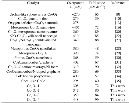
[image:7.596.84.507.393.730.2]It is very important to compare the OER performance of the catalysts with the related literature results. Table 1 shows the overpotentials and Tafel slopes of the catalysts for OER in 1 M KOH. It can be seen that Co3O4-1 catalyst in this work is not inferior to other reported highly efficient OER catalysts.
Table 1. Comparison of the electrocatalytic performances of Co3O4 catalysts and the related materials reported in literature at the current density of 10 mA cm‒2 in 1 M KOH for OER.
Catalyst Overpotenti
al (mV)
Tafel slope (mV dec−1)
Reference
Urchin-like sphere arrays Co3O4 ~270 65 [8]
Co3O4 quantum dots 270 39 [10]
Oxygen deficient Co3O4 nanorods 275 - [13]
Mesoporous Co3O4 nanowires ~405 72 [16]
Co3O4 mesoporous nanostructures 360 89 [20]
rGO-Co3O4 yolk-shell nanocage 410 85 [22]
Co3O4/NiCo2O4 double-shelled nanocages
340 88 [27]
Mesoporous Co3O4 nanoflakes 380 48 [28]
Mesoporous Co3O4 390 74 [29]
Porous Co3O4 nanosheets 368 59 [30]
Co3O4 nanocubes/graphene 402 67 [31]
Co3O4-Cnanowire arrays/Ni foam 310 90 [32] Co3O4 nanocubes/N-doped graphene 280 69 [33]
CoP hollow polyhedron 400 57 [34]
Coral-like CoSe 295 40 [35]
Co3O4-1 308 72 This work
Co3O4-2 342 80 This work
Co3O4-3 350 84 This work
Figure 5. CV curves of four kinds of Co3O4 catalysts at the scan rate of 5 mV s‒1.
In Fig. 4a, there is a peak before the OER occurs. As shown in the CV curves at the corresponding potential range (Fig. 5), a pair of redox peaks for Co3O4 at 1.47 V (anodic) and 1.37 V (cathodic) is observable for the four kinds of Co3O4 catalysts. It was reported that the oxidation of Co3+ to Co4+ is crucial for OER activity [29, 36]. At the corresponding potential range, there is not only one redox couple of CoIII/CoIV, but also another redox couple of CoII/CoIII [29, 37]. But only one redox couple can be seen clearly in Fig. 5.
Figure 6. (a) CV curves of Co3O4-1 in 1 M KOH measured at different scan rates (5~100 mV s‒1); (b) linear calibration relationship between the anodic and cathodic peak current densities and the square root of the scan rate.
[image:8.596.73.523.441.618.2]
transformation of CoIII/CoIV (1.2 and 1.15 V are attribute to CoII/CoIII). The cathodic peak current density (ipc) and anodic peak current density (ipa) increase as the increase of the scan rate. Apparently, the relationship between the peak current densities of CoIII/CoIV and the square root of the scan rate (ν1/2
) can be evaluated by the series linear plots (Fig. 6b). The calibration plots can be described by equations (2) and (3):
ipa = 6.18 ν1/2 ‒ 4.67 (R2 = 0.997) (2) ipc = ‒4.67 ν1/2 + 6.80 (R2 = 0.996) (3)
According to the characteristic indexes of the heterogeneous electron transfer reaction, the electron transfer kinetics of the CoIII/CoIV couple is controlled by diffusion confinement. It indicates that the peaks in Fig. 4a can be assigned to the formation of CoIV from CoIII that is easy to happen.
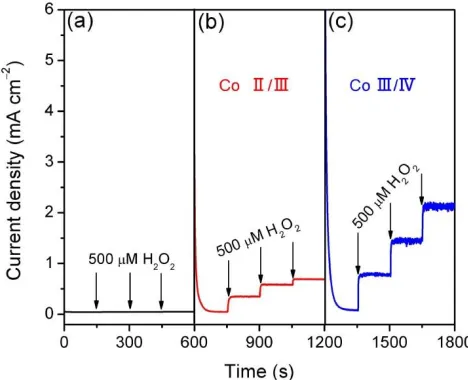
Figure 7. I-t curves of Co3O4-1 for the addition of 500 μM H2O2 in 1 M KOH each time when the potential is holding at 1 V (a), 1.22 V (b), and 1.45 V (c).
[image:9.596.180.414.269.459.2][image:10.596.75.522.206.387.2]
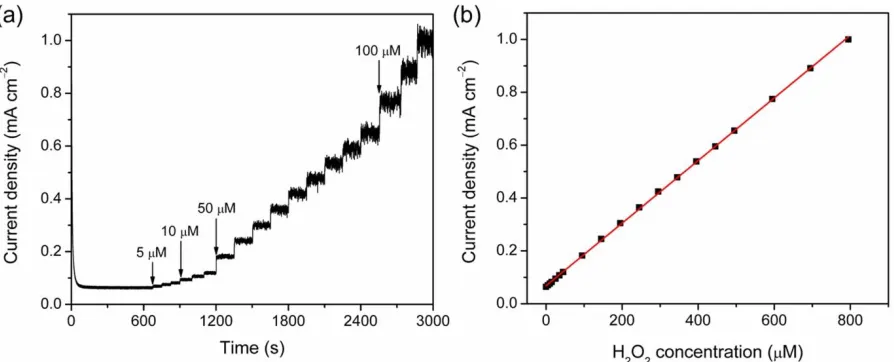
displays a typical staircase curve in Fig. 8a. The Co3O4 activity in the reaction with H2O2 can be described by the calibration curve in Fig. 8b. The increase of the current density is proportional to the H2O2 concentration, and the linear response for H2O2 is expressed as: I (μA) = 1.18 (μA μM‒1) c (μM, H2O2) + 68 (μA) (R2 = 0.997). Derived from the calibration curve, the electrochemical response of Co3O4 towards H2O2 can reach as low as 17.5 μM (S/N = 3). The results suggest that CoIII/CoIV redox couple formed at 1.45 V can oxide H2O2 at low concentration. It indicates that the fourth electron transfer step of OER is a fast kinetics process.
Figure 8. I-t curve of Co3O4-1 (holding at 1.45 V) for the successive addition of H2O2 in 1 M KOH; (b) linear calibration relationship of current densities vs. H2O2 concentration.
As shown in Fig. 7, the current density at 1.45 V is as small as that at 1 V before H2O2 is not added. It indicates that the third step (OH oxidation to OOHads) does not happen at the potential of 1.45 V. If the third step happens, the generated OOHads can be rapidly oxidized to O2ads by the nearby CoIII/CoIV redox couple. It is obviously that the strong oxidation ability of the CoIII/CoIV redox couple for OOHads could facilitate the formation of O2ads. The OER mechanism is complex, many factors may affect the electron transfer pathway, including the formation/decomposition of unstable intermediate-oxides on the surface of catalysts, the recombination of oxygen atoms, the desorption/adsorption processes, the chemical reactions and the electroconductivity of the catalysts. More works should be carried out for understanding the OER mechanism.
4. CONCLUSIONS
In summary, urchin-like Co3O4, Co3O4 nanosheets, Co3O4 nanoparticles, and Co3O4 nanospheres were successfully synthesized. Among the four kinds of Co3O4 catalysts with different morphologies, the urchin-like Co3O4 shows the best OER catalytic performance. The urchin-like Co3O4 exhibits a low overpotential of 308 mV at the current density of 10 mA cm
−2
Co3O4-1 is a two-step process, in which the peroxo species (OOHads) is the intermediate. The urchin-like Co3O4 shows excellent electrooxidation performance towards H2O2 when CoIV cations formed (at 1.45 V vs. RHE) which indicates that the fourth electron transfer step of OER is a fast kinetics process on Co3O4 catalysts.
ACKNOWLEDGEMENTS
The work was supported by the National Natural Science Foundation of China (21603184, 21675139, 21575123); and the joint research fund between Collaborative Innovation Center for Ecological Building Materials and Environmental Protection Equipments and Key Laboratory for Advanced Technology in Environmental Protection of Jiangsu Province.
References
1. W. X. Lv, J. Zhou, J. J. Bei, R. Zhang, L. Wang, Q. Xu and W. Wang, Appl. Surf. Sci., 393 (2017) 191.
2. W. X. Lv, J. J. Bei, R. Zhang, W. J. Wang, F. Y. Kong, L. Wang and W. Wang, ACS Omega, 2 (2017) 2561.
3. M. Leng, X. L. Huang, W. Xiao, J. Ding, B. H. Liu, Y. H. Du and J. M. Xue, Nano Energy, 33 (2017) 445.
4. Q. Zhao, Z. Yan, C. Chen and J. Chen, Chem. Rev., 117 (2017) 10121.
5. W. X. Lv, S. X. Liu, R. Zhang, W. J. Wang, Z. X. Wang, L. Wang and W. Wang, J. Mater. Sci., 53 (2018) 4939.
6. T. Audichon, S. Morisset, T. W. Napporn, K. B. Kokoh, C. Comminges and C. Morais, Chemelectrochem, 2 (2015) 1128.
7. Z. S. Song, X. P. Han, Y. D. Deng, N. Q. Zhao, W. B. Hu and C. Zhong, ACS Appl. Mater. Inter., 9 (2017) 22694.
8. R. C. Li, D. Zhou, J. X. Luo, W. M. Xu, J. W. Li, S. S. Li, P. P. Cheng and D. S. Yuan, J. Power Sources, 341 (2017) 250.
9. W. Zhang, W. Z. Lai and R. Cao, Chem. Rev., 117 (2017) 3717.
10. G. X. Zhang, J. Yang, H. Wang, H. B. Chen, J. L. Yang and F. Pan, ACS Appl. Mater. Inter., 9 (2017) 16159.
11. Y. R. Liu, G. Q. Han, X. Li, B. Dong, X. Shang, W. H. Hu, Y. M. Chai, Y. Q. Liu and C. G. Liu, Int. J. Hydrogen Energ., 41 (2016) 12976.
12. J. D. Blakemore, H. B. Gray, J. R. Winkler and A. M. Mueller, ACS Catal., 3 (2013) 2497. 13. G. Cheng, T. Kou, J. Zhang, C. Si, H. Gao and Z. Zhang, Nano Energy, 38 (2017) 155. 14. Y. X. Zhang, X. Guo, X. Zhai, Y. M. Yan and K. N. Sun, J. Mater. Chem. A, 3 (2015) 1761. 15. S. Xu, J. L. Tong, Y. Liu, W. Hu, G. B. Zhang and Q. H. Xia, J. Renew. Sustain. Ener., 8 (2016)
044703.
16. Y. Wang, T. Zhou, K. Jiang, P. Da, Z. Peng, J. Tang, B. Kong, W. B. Cai, Z. Yang and G. Zheng, Adv. Energy Mater., 4 (2014) 1400696.
17. L. Xu, Q. Q. Jiang, Z. H. Xiao, X. Y. Li, J. Huo, S. Y. Wang and L. M. Dai, Angew. Chem. Int. Ed., 55 (2016) 5277.
18. X. L. Zhang, J. B. Zhang and K. Wang, ACS Appl. Mater. Inter., 7 (2015) 21745.
19. H. Tueysuez, Y. J. Hwang, S. B. Khan, A. M. Asiri and P. Yang, Nano Res., 6 (2013) 47. 20. H. Sun, Y. Zhao, K. Molhave, M. Zhang and J. Zhang, Nanoscale, 9 (2017) 14431.
13534.
23. B. C. He, X. X. Chen, J. M. Lu, S. D. Yao, J. Wei, Q. Zhao, D. S. Jing, X. N. Huang and T. Wang, Electroanal., 28 (2016) 2435.
24. J. H. Zhang, J. Y. Feng, T. Zhu, Z. L. Liu, Q. Y. Li, S. Z. Chen and C. W. Xu, Electrochim. Acta, 196 (2016) 661.
25. I. Katsounaros, S. Cherevko, A. R. Zeradjanin and K. J. J. Mayrhofer, Angew. Chem. Int. Ed., 53 (2014) 102.
26. H. Y. Wang, S. F. Hung, H. Y. Chen, T. S. Chan, H. M. Chen and B. Liu, J. Am. Chem. Soc., 138 (2016) 36.
27. H. Hu, B. Guan, B. Xia and X. W. Lou, J. Am. Chem. Soc., 137 (2015) 5590.
28. S. Q. Chen, Y. F. Zhao, B. Sun, Z. M. Ao, X. Q. Xie, Y. Y. Wei and G. X. Wang, ACS Appl. Mater. Inter., 7 (2015) 3306.
29. W. Song, Z. Ren, S. Y. Chen, Y. Meng, S. Biswas, P. Nandi, H. A. Elsen, P. X. Gao and S. L. Suib, ACS Appl. Mater. Inter., 8 (2016) 20802.
30. Z. P. Li, X. Y. Yu and U. Paik, J. Power Sources, 310 (2016) 41.
31. P. Zhang, X. T. Han, H. Hu, J. Z. Gui, M. Y. Li and J. S. Qiu, Catal. Commun., 88 (2017) 81. 32. J. T. Ren, G. G. Yuan, C. C. Weng and Z. Y. Yuan, ACS Sustain. Chem. Eng., 6 (2018) 707. 33. S. K. Singh, V. M. Dhavale and S. Kurungot, ACS Appl. Mater. Inter., 7 (2015) 442. 34. M. J. Liu and J. H. Li, ACS Appl. Mater. Inter., 8 (2016) 2158.
35. M. Liao, G. F. Zeng, T. T. Luo, Z. Y. Jin, Y. J. Wang, X. M. Kou and D. Xiao, Electrochim. Acta, 194 (2016) 59.
36. B. S. Yeo and A. T. Bell, J. Am. Chem. Soc., 133 (2011) 5587.
37. A. Bergmann, E. Martinez-Moreno, D. Teschner, P. Chernev, M. Gliech, J. F. de Araujo, T. Reier, H. Dau and P. Strasser, Nature Commun., 6 (2015) 8625.
38. S. Barkaoui, M. Haddaoui, H. Dhaouadi, N. Raouafi and F. Touati, J. Solid State Chem., 228 (2015) 226.