Simultaneous Space Charge and Conduction Current
Measurements in Solid Dielectrics under High DC Electric Field
W S Lau and G Chen
School of Electronics and Computer Science, University of Southampton, United Kingdom
Abstract — Crosslinked polyethylene (XLPE) has been used for ac power cable insulation up to 500 kV for many years. There is a tendency to use XLPE for dc power cable. However, the easy formation of space charge under dc electric field within XLPE is a major concern for such an application. Therefore, a better understanding of charge dynamics is important. In this paper, we report the relationship between space charge dynamics and electrical conduction current in XLPE using the modified pulsed electroacoustic system. The effect of electrode material on both charge dynamics and current has been investigated using semiconducting material and aluminium. It has been found charge dynamics in the material depend on electrode configuration. More importantly, it has been noticed that the so called space charge limited transient current peaks are closely related to the meetings of negative and positive charge front in the bulk of the sample.
Index Terms — Space charge, XLPE, Modified PEA, Transient space charge limited current.
I. INTRODUCTION
DC transmission is more suited to long distance or high power applications than AC transmission due to its low energy loss. With the introduction of new solid state ac/dc and dc/ac converters, the need for suitable dc insulation has increased in recent years. Crosslinked polyethylene (XLPE) insulation is commonly used in AC power cables and 500 kV XLPE insulated cables have been in service since 1996 [1]. However, for dc transmission, XLPE cables are still under extensive study due to serious concern about space charge formation in the bulk. It has been found that the performance of extruded polymeric hvdc cables insulation strongly depends upon charging phenomena
such as charge injection, accumulation and
transportation and all these are sensitive to additives, electrode materials, ageing, temperature, stress and so on. Space charge may accumulate in the insulation when a hvdc voltage is applied across it, causing abnormal electric stress distribution. If the space charge density is sufficiently high, the local field strength may exceed the anticipated breakdown strength of the dielectric leading to a significant higher probability of causing a premature failure or initiating a pre-failure event such as electrical tree. Significant charge densities can be generated during dc testing of ac cables before installation, leading to premature when ac stress is
applied subsequently. Therefore, the need to investigate and understand space charge formation is crucial in hoping conceivable solutions of eliminating or at least reducing space charge accumulation to be established. One of the problems associated with space charge formation in XLPE is crosslinking by-products. In the manufacturing process of XLPE cables, dicumyl peroxide (DCP) is widely used as a crosslinking agent. Several curing decomposition products are generated during this crosslinking process using DCP. Variable amount of acetophenone, α-methylstyrene and cumyl-alcohol, methane and water are produced in addition to crosslink. Curing decomposition products of low molecular weight such as methane and water are very volatile that they are lost from the insulation rather soon. High boiling point substances such as acetophenone, α -methylstyrene and cumyl-alcohol can be remained in the insulation for a long period of time. It has been reported [2] that space charge is highly affected by the presence of by-products (curing decomposition products) in insulation. The existence of fast moving charge packet [3] in XLPE has also been accredited to them.
In this paper, we start with a brief description of the improved Pulsed Electroacoustic (PEA) system that is capable of performing charge and current measurement simultaneously, with a particular attention to the design of the electrode system. This is followed by the application of the improved PEA system to study the space charge and conduction current characteristics in XLPE insulation. Experiments were carried out on fresh (undegassed) and degassed XLPE to demonstrate the influence of crosslinking by-products as well as importance of the electrode configuration. The detailed discussion of results is given in section 4. The summary of the investigation and future work are shown in section 5.
II.THE IMPROVED PEAMEASUREMENT SYSTEM
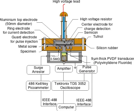
mechanically bounded to the solid dielectric will interact with the pulsed field producing a mechanical force on the material and subsequently launching acoustic waves to travel through the material. The acoustic signals are then detected by a piezo-electric sensor. Through a deconvolution technique and calibration, a quantitative description of charge across the sample can be obtained. The spatial resolution of the system is determined by the pulse width and sensor thickness. To measure space charge and current simultaneously the conventional PEA system has to be modified. The cross-sectional view of the improved PEA setup used to carry out the investigation is shown in figure 1.
Figure 1 Schematic diagram of the improved PEA.
A single connection is made between the top electrode (~50mm diameter) and high voltage supply through a
1MΩ resistor. The main difference between a
conventional PEA and the modified PEA system is the bottom electrode configuration. The bottom electrode system is made up of three electrodes, two concentric ring electrodes surrounding a central electrode, rather than a single electrode. The outer ring also known as the guard ring is used as an electrode for pulse voltage application and to prevent the measurement of surface leakage current. The pulse voltage in a conventional PEA is applied to the sample from the top electrode via a coupling capacitor. The inner ring electrode is used for electric current detection, which is connected to a Keithley 486 picoammeter via a 0.5MΩ limiting resistor and surge arrestor for current limiting purpose in case of specimen breakdown. This arrangement enables simultaneous measurement of charge and current on the same specimen to ensure a better correlation.
III.CONDUCTION CURRENT AND SPACE CHARGE
A. Sample Preparation
Cross-linking is the process whereby the polymer structure is modified through the formation of chemical
bonds between the polymer chains, resulting in a better thermal performance. The most common method of chemical cross-linking is to trigger a thermally activated catalyst, such as dicumyl peroxide (DCP), by subjecting the polymer to high temperatures. XLPE may have good thermal performance compared to low density polyethylene (LDPE) but along with it comes the problem associated with the residual crossed-linked by-products. Under high electric stress, they can be dissociated into ionic pairs, forming heterocharge at the semicon/insulator interfaces which enhances the electric stress. This is a main cause for concern since majority of electric breakdown in cables occurs at the interfaces. One of the most common material treatments adopted by cable manufacturer to improve on the performance of high voltage power cables is degassing. Degassing is the process of subjecting the XLPE to moderately high temperature thereby removing volatile residual by-products. All samples used in the present study were
manufactured using cable grade cross-linked
polyethylene (Borealis XL4201S) with semi-con electrodes made from the same grade of polyethylene material, but loaded with carbon black to increase its conductivity (Borealis LEO592). XLPE specimens used were press-moulded from granules to a ~200 µm plaque. These granules were subjected to a temperature of 200°C for ~10 minutes, under such environment DCP will be decomposed to create crosslinked structure. Such high temperature is necessary to ensure that the DCP content is totally decomposed. Freshly made specimens were used immediately for testing. Degassed specimens were prepared by placing freshly made specimens into a vacuum oven at 90°C. It has been noticed that there was a weight reduction of ~0.51% after 24 hours of degassing at 90°C, further degassing up to 72 hours did not lower the weight. Therefore, all degassed specimens had undergone heat treatment for 24 hours. Three types of electrode material were used, namely (a) semicon press-moulded from granules into thin sheet was attached onto specimen, (b) aluminium was evaporated onto the specimen surface and (c) the solid aluminium block of the PEA rig’s bottom cell. The purpose of having two different ways of preparing aluminium electrode (b) and (c), was to demonstrate the importance of contact surfaces. A thin layer of silicon oil was applied for all experiments on all contact surfaces to aid acoustic signal transmission.
B. Experimental protocols
Sample preparation and the electrode material can play a critical role in determining charge carriers’ behaviours. Formation of the electrode is of great importance. In laying down the conductive material, the surface should not be chemically changed and there should be no gaps between the electrode and sample. Vacuum deposition of metal such as silver, aluminium or gold is commonly employed. In the present study, aluminium (Al) and semicon (XLPE loaded with carbon black, Sc) were
486 Keithley Picoammeter
Surge Arrester
Computer IEEE-488
Interface Amplifier
Tektronix TDS 3052 Oscilloscope
Pulse Generator
IEEE-488 Interface High voltage lead
High voltage resistor Aluminium top electrode
(50mm diameter)
Silicon rubber
9 thick PVDF transducer (Polyvinylidene Fluoride) Metal screw
Semicon
Specimen Guard electrode for pulse injection Ring electrode for current detection
Center electrode for charge detection
Tufnol
0 500 1000 1500 2000 2500 0
5 10 15 20 25 30 35 40 45 50 55
M
e
a
s
u
re
d
C
u
rr
e
n
t
D
e
n
s
it
y
(
µ
A
/m
2)
Time (minutes)
0 10 20 30 40 50 60 20
25 30 35 40 45 50 55 60 65 70
M
e
a
s
u
re
d
C
u
rr
e
n
t
D
e
n
s
ity
(
µ
A
/m
2)
Time (minutes)
S
p
e
c
im
e
n
T
h
ic
k
n
e
s
s
Time (minutes)
C
h
a
rg
e
D
e
n
s
it
y
(
C
/m
3) Anode (+)
Cathode (-)
[image:3.595.314.540.113.448.2]used to examine their individuality on space charge generation, transportation and accumulation processes in pace with external measured current behaviour. Al electrode is often used in laboratory as electrode for electrical property measurements while Sc is used extensively in polymeric power cables to eliminate partial discharge and smooth the electric field. In most conventional PEA measurements [5], the bottom Al block was conveniently served as an electrode. Considering the possible difference between evaporated Al and Al block, both types of electrode were used. Two different electrode configurations were selected to carried out the tests, they were (a) evaporated Al(-) with Sc(+) and (b) solid aluminium block Al(-) with Sc(+). The signs (-) and (+) refer to the cathode and the anode respectively. Combined with the material treatment, four sets of experiments have been carried out. As both current and space charge are influenced by temperature with current in particular, the electrode system with sample was in an oven at a temperature of 30°C. Measurements were taken at every 6 seconds intervals throughout the stressing period. Table 1 shows a summary of each experimental configuration.
Table 1 XLPE experimental configuration
No Specimen type Electrode configuration
1 Fresh XLPE Solid Al block(-) with
Sc(+)
2 Fresh XLPE Evaporated Al(-) with
Sc(+)
3 Degassed (at 90°C)
XLPE
Solid Al block(-) with Sc(+)
4 Degassed (at 90°C)
XLPE
Evaporated Al(-) with Sc(+)
IV.EXPERIMENTAL RESULTS
All the measurements were repeated to ensure the consistence of the same type of sample. It has been found that the conduction current varies slightly (<10%) but the space charge distribution gives almost identical results at the end of the stressing period. The applied voltage is 20 kV, resulting in an applied electric field of ~100 kV/mm.
Figures 2 to 5 show the measured current density and correspondent space charge profiles at time as stated in individual graph for specimens 1 to 4 as described in table 1. From current density curves they generally follow a decent trend as one might expect from a response of dielectric to a dc voltage application. However, there are transient current peaks occurring within the first 60 minutes after the application of dc voltage as illustrated in the insertion in each figure. At the same time there are significant developments in space charge movement within the material. This can be clearly viewed using space charge colour contour representation. A few distinctive differences between
these experimental results for the first 60 minutes can be summarised.
Figure 2 Current density and space charge density
colour contour graph for the first 35 minutes in fresh XLPE No. 1 using solid Al block(-) with Sc(+).
[image:3.595.64.288.368.464.2]0 500 1000 1500 2000 2500 4 6 8 10 12 14 16 18 M e a s u re d C u rr e n t D e n s it y ( µ A /m 2) Time (minutes)
0 10 20 30 40 50 60
10 12 14 16 18 20 22 24 M e a s u re d C u rr e n t D e n s it y ( µ A /m 2) Time (minutes) S p e c im e n T h ic k n e s s C h a rg e D e n s it y ( C /m 3) Anode (+) Cathode (-) Time (minutes)
0 500 1000 1500 2000 2500
4 6 8 10 12 14 16 M e a s u re d C u rr e n t D e n s it y ( µ A /m 2) Time (minutes)
0 10 20 30 40 50 60 70 80 90 100 10 11 12 13 14 15 16 17 18 M e a s u re d C u rr e n t D e n s it y ( µ A /m 2) Time (minutes) S p e c im e n T h ic k n e s s C h a rg e D e n s it y ( C /m 3) Anode (+) Cathode (-) Time (minutes)
0 500 1000 1500 2000 2500
5 6 7 8 9 10 11 12 13 14 15 M e a su re d C u rr e n t D e n si ty ( µ A /m 2) Time (minutes)
0 10 20 30 40 50 60 70 80 90 100 8 10 12 14 16 18 20 M e a su re d C u rr e n t D e n si ty ( µ A /m 2) Time (minutes) S p e c im e n T h ic k n e s s C h a rg e D e n s it y ( C /m 3) Anode (+) Cathode (-) Time (minutes) the first transient current peak in fresh specimens is
shorter (compared between the same electrode configuration) than in degassed specimens.
Figure 3 Current density and space charge density
colour contour graph for the first 35 minutes in fresh XLPE No. 2 using evaporated Al(-) with Sc(+).
At the end of stressing period, the magnitude of the conduction current does show significant difference among these samples. However, there are remarkable differences in charge distribution, depending on both electrode material and material treatment.
Figure 4 Current density and space charge density
colour contour graph for the first 35 minutes in degassed XLPE No. 3 using solid Al block(-) with Sc(+).
Figure 5 Current density and space charge density
colour contour graph for the first 35 minutes in degassed XLPE No. 4 using evaporated Al(-) with Sc(+).
V.DISCUSSION
A. Electrode effect
[image:4.595.317.539.87.255.2] [image:4.595.57.289.127.454.2] [image:4.595.314.532.312.626.2]3) and degassed specimens 3 with 4 (figures 4 and 5). Specimens 1 and 2 are fresh XLPE having solid and evaporated aluminium as the cathode respectively. Space charge results from specimen 1 reveal that very fast moving positive and negative packet charge travelling from one electrode to the other appeared one after another, it was more apparent for the first 20 minutes. The charge packet behaviour becomes less prominent with time and so does the oscillatory current. From the dynamic space charge density colour contour graph of specimen 2 shown in figure 3, it can be seen that due to the fact that evaporated aluminium at the cathode has a higher potential barrier height compared to solid Al/silicon oil(-) [6], positive charge carrier was the dominant party throughout the stressing period and very infinitesimal amount of negative carrier near to the cathode was captured. After voltage was applied, a large positive charge packet was seen moving towards the cathode, at ~3 minutes later, this positive charge packet started to diminish, at the same time the measured current increased for about 7 minutes. There were subsequent smaller magnitude of overlapping positive charge packets; these packets did not cause perceptible increase in the measured current.
Although specimens 1 and 2 were the same type of fresh XLPE but under the influence of the electrode materials (as explained in [6] that the actual contact for solid aluminium block electrode is with a layer of silicon oil in between the specimen/solid aluminium and evaporated aluminium is in direct contact with the specimen), it displayed entirely different characteristics. Specimen 2 using evaporated aluminium cathode did not show continual fast moving charge packet that corresponds to the oscillatory current as in specimen 1. This implies that the occurrences of fast moving packet charge depend on not only the applied electric field as reported in [7-8], it also depends on the chosen electrode material.
The reported transit time for each charge packet from one electrode to the other varies. At an applied field of 120 kV/mm, Kon et al [7] witnessed moving negative charge packets in oxidized XLPE doped with antioxidant (using gold electrodes on both sides of the specimens), transiting time was about 6 to 7 minutes and it lasted for about 90 minutes. See et al [8] perceived moving positive charge packets (at 120 kV/mm applied field) in specimen peeled from actual XLPE cable (specimen not coated with electrode, using solid aluminium block as the cathode and evaporated aluminium coated on the semicon as the anode) taking about 2.5 hours to cross from the anode to the cathode, persisted for 48 hours. In our case, at an electric field of ~102.5 kV/mm with solid aluminium block/silicon oil/XLPE at the cathode and semcon/silicon oil/XLPE at the anode, both positive and negative charge packets moving towards the counter electrode but positive was the more prominent one. The transit time for the charge packet was ~6 minutes, it was more obvious for the first
20 minutes and it decays gradually with time but can be vaguely seen up to ~60 minutes. The different transit time and behaviour in these three cases inferred that formation of packet charge behaviour might also rely on the content of XLPE and the way XLPE specimen was prepared.
Degassed specimens 3 and 4 utilised solid and evaporated aluminium as the cathode respectively. Figure 5(b) shows the space charge colour contour graph (the first 35 minutes) of specimen 3, it exhibits positive and negative charge packets, the speed of these charge packets was not as fast as those in fresh specimen1. There are clearly three growing and fading charge packets, the speed of these charge packets is slow, before one packet reaches the counter electrode another one is formed (overlapping of charge packet) therefore we cannot see solitary positive or negative charge packets reaching the opposite electrode. Every of the successive positive and negative breeding charge packet lessen some time after they met up with each other. This might be the reason for the slow continuous increase of measured current for the period of about 15 minutes instead of the abrupt current trend as in specimen 1. Figure 6(b) is the space charge contour graph of specimen 4, for the fact that evaporated aluminium electrode hinders carrier injection (compared to solid Al/silicon oil electrode), the positive charge packet dominated the whole time but gradual increasing observable small quantity of negative carriers was seen from the ~9th minute. And there are several large overlapping positive and small negative charge packets within the first 35 minutes. The similarity between specimens 3 and 4 is the consecutive overlapping positive and negative charge packet formation and both charge packets lessen some time after they met. Specimen 4 too exhibited continuous slow increase in the measured current instead of abrupt current trend. There are a few obvious doubts that can be questioned, like why (a) the charge carrier’s movement were much slower in degassed specimens than in fresh specimens and (b) the evaporated aluminium cathode used in degassed specimen can injected more charge carriers than when used in fresh specimen, this will be discussed in the next section dealing with the contribution of by-products.
B. By-products effect
injected homocharges overlapped the existence of heterocharges near to the electrode.
A comparison between fresh and degassed specimens 1 with 3 and 2 with 4 for the first 35 minutes will demonstrate the role of the by-products. Fresh specimen 1 shows distinct fast moving positive and negative packet charge reaching the cathode and the anode respectively. The dissociated negative charge carriers together with electrons injected from the cathode moved towards the anode, at the same time, the dissociated positive charge carriers and holes injected from the anode travelled towards the cathode. This creates an image as if all the positive and negative charges were injected from the electrodes and were moving speedily from one electrode to the other, but in fact the creation of dissociated species had played a part in making the carriers looked moving faster. The presence of by-products increases the conductivity (at least for the first hundred minute) that led to the higher measured current density and the time for the appearance of the first transient current peak also shorten.
The collapse of each positive charge packet at the cathode was caused by the extra injection of electrons that increases the measured current. The transit time of each packet depends on the rate of dissociation and the amount of dissociation species available. Notice that the packet charge decays with time suggested the availability of dissociable species reduced with time too. Degassed specimen 3 shows a slower moving negative and positive charge packet, both positive and negative show successive overlapping charge packets and they diminished some time after meeting with each other. Degassed specimen 3 has undergone heat treatment and it is believed to have majority of by-products removed. Therefore the positive and negative charge packet contained mostly injected charges from the electrodes, and these slower moving charges need more time to get across the bulk and therefore cause the overlapping of successive charge packet.
Fresh specimen 2 on the other hand only shows large positive charge packet due to the fact that aluminium electrode hinders charge injection which in this case electrons injection. By-products dissociation still exists but because of evaporated Al(-), the limited amount of injected electrons were overshadowed by the injected holes from the anode and dissociated positive ions which have travelled near to the cathode, that is why very little electrons were seen near to the cathode throughout the stressing period. And also the domineering positive charge carriers had overshadowed the dissociated electrons and negative ions. On the contrary, degassed specimen 4 had impurities removed; therefore positive charge carriers containing mostly holes injected from the anode were present. The dominating injected positive charge moved slower which gave time to the limited amount of injected electrons to be visible near to the cathode. This resulted in a longer time taken for the slower moving injected
charges to get extracted. The first occurrence of increase in the measured current for fresh specimen2 was at the ~3.2th minute and degassed XLPE at the ~9th minute. The exact mechanisms of influence of crosslinking by-products are more complicated as individual component may behave differently under the influence of the electric field.
VI.CONCLUSIONS
An attempt has been made to reveal the relationship between transient current and space charge profile in XLPE films. The results clearly show that the transient current are clearly related to space charge dynamics. The transient space charge limited current peak is related to the meeting of positive and negative charge fronts in the presence of both positive and negative charge carriers. As the existing transient space charge limited current was based on single charge carrier, new theory is required to be developed. The results also demonstrate that both electrode and heat treatment have a significant effect on the transient current and space charge dynamics.
REFERENCES
[1] M. Fukawa, T. Kawai, Y. Okano, S. Sakuma, S. Asai, M. Kanaoka and H. Yamanouchi, “Development of 500 kV XLPE cables and accessories for long distance underground transmission line - Pt III” IEEE Trans on PD 11 627—634, 1996.
[2] Y. F. F. Ho, Y. L. Chong and G. Chen, “Temperature effect on the space charge characteristics in as received and degassed XLPE insulation under dc stressing condition” CEIDP Albuquerque 241—244, 2003.
[3] N. Hozumi, T. Takeda and H. Suzuki, "Space Charge Behavior in XLPE Cable Insulation under 0.2-1.2MV/cm dc Fields", IEEE Trans on DEI 5 82-90, 1998.
[4] N. H. Ahmed and N. N. Srinivas, “Review of space charge measurements in dielectrics IEEE Trans on DEI 4 644-656, 1997.
[5] T. Takada, “Acoustic and optical methods for measuring electric charge distributions in dielectrics” IEEE Trans on DEI 6 519-547, 1999.
[6] K. S. Suh, J. H. Sun and S. N. Jin, "Effects of Constituents of XLPE on the Formation of Space Charge", IEEE Trans on DEI 1 1077-1083, 1994. [7] H. Kon, Y. Suzuoki, T. Mizutani, M. Ieda and N. Yoshifuji, "Packet-like Space Charges and Conduction Current in Polyethylene Cable Insulation", IEEE Trans on DEI 3 380-385, 1996.