- 1 -
Simulating damage onset and evolution in fully bio-resorbable composite
under three-point bending
Xi Gao1, Menghao Chen2, Xiaogang Yang1, Lee Harper2, Ifty Ahmed2, Jiawa Lu1*
1 International Doctoral Innovation Centre, University of Nottingham Ningbo China, 315100,
China
2 Faculty of Engineering, University of Nottingham, NG7 2RD, United Kingdom
* Corresponding author: mailto: [email protected]
Abstract
This paper presents a strain-based damage model to predict the stress-strain relationship and investigate the damage onset and evolution of the fibre and matrix of a fully bio-resorbable phosphate glass fibre reinforced composite under three-point bending. The flexural properties of the composite are crucial, particularly when it is employed as implant for long bone fracture. In the model, the 3D case of the strain and stress was used and the response of the undamaged material was assumed to be linearly elastic. The onset of damage was indicated by two damage variables for the fibre and matrix, respectively. The damage evolution law was based on the damage variable and the facture energy of the fibre and matrix, individually. A finite element (FE) model was created to implement the constitutive model and conduct numerical tests. An auto-adaptive algorithm is integrated in the FE model to improve the convergence. The FE model was capable of predicting the flexural modulus with around 3% relative error, and the flexural strength within 2% relative error in comparison with the experimental data. The numerical indices showed that the top surface of the sample was the most vulnerable under three-point bending. It was also found that the damage initiated in the fibre, was the primary driver for composite failure under three-point bending.
Key words: continuum damage mechanics, flexural strength, finite element analysis, bio-resorbable composite
1
.
Introduction
- 2 -
desirable reinforcement because of the mechanical properties it has achieved and it is fully bio-resorbable, releasing calcium and phosphate ions which are ideal for bone repair applications [11, 12]. Considerable effort has been put into investigating the mechanical properties of these materials [4, 9, 13-15],
particularly the flexural strength [16-18], however damage initiation and accumulation in the fibre and matrix under three-point bending has not been investigated before. Therefore, the current paper seeks to develop an effective approach to assess the damage accumulation and resulting reduction in flexural performance of this bio-resorbable glass fibre reinforced polymer composite. Knowledges about the damage onset and evolution of the fibre and matrix extracted from this study are beneficial to the manufacturing of this type of composites, e.g. the selection of the fibre and matrix materials, the improving of manufacturing method, and possible optimization of fibre/matrix configuration.
Subsequently, the results of this study are useful for pushing the research of employing bio-resorbable composites as bone fixation device material forward, which, ultimately, is beneficial to patients in the need of using bone fixation devices.
Damage initiation and evolution in the composite can be described using continuum damage mechanics (CDM), as long as the problem size is assumed to be sufficiently larger than the defect/microcrack size, to facilitate homogenisation [19]. Typically, a progressive damage model (PDM) consists of three steps: stress analysis, material properties degradation and failure analysis [20-22]. The crucial part of a PDM is to appropriately define the damage initiation criterion and evolution law. For unidirectional fibre
reinforced composites, early work by Hill [23] was adopted by Tsai [24] to simulate the damage initiation in fibre reinforced composites. Hill’s model was only intended for anisotropic ductile metals, and the yield stress in tension and compression were considered to be the same, which is unrealistic for the bio-resorbable composites whose compressive and tensile strength are different. Hoffman [25] later proposed a phenomenological fracture condition for orthotropic brittle materials which was capable of simulating the different properties of fibre reinforced composites in both the longitudinal and transverse directions. Hoffman developed Hill’s model to consider different tensile and compressive yield stresses. However, both models lacked the capability of simulating the onset and evolution of damage. Matzenmiller et al. [26] proposed a damage model based on Hashin’s criterion [27] involving five damage variables to simulate the elastic-brittle nature of the fibre reinforced composites. The tensile and compressive damage was modelled for both fibre and matrix, respectively. The 3D-Hashin and Tsai-Wu failure criteria were adopted to describe the damage initiation of yarns [28], in which the damage evolution of composites was strongly dependent on the reduction coefficients, which were controlled by the local stress and strain. Zhou et al. [29] and Fang et al. [30] proposed a modified 3D-Hashin failure criterion to model the
damage initiation and evolution, and the reduction coefficients introduced by Murakami’s theory [31] was adopted which were controlled by the equivalent stresses and equivalent strains. For these Hashin and Tasi-Wu based criterion, at least six different damage mechanisms were included, leading to a large number of equations which resulted in high computational cost. Linde et al. [32] developed a 2D criterion for progressive damage of fibre metal laminates, which was based on a strain-based continuum damage mechanics. Unlike Matzenmiller’s model, Linde’s model integrated the tensile and compressive damage as two damage variables for the fibre and matrix, respectively, but required the tensile and compressive strength of the fibre and matrix as input parameters. Lu et al. [33] extended the 2D failure criterion to 3D and adopted it to model the tensile properties of 3D braided composites. In both Linde’s model and the modified model by Lu et al., the shear strain in the fibre direction was not part of the damage formulation. In the work of Chengyu et al. [34], a modified 3D model based on Linde’s model was proposed to
- 3 -
In this paper, the modified Linde’s model in [34] has been adopted to simulate the three-point bending of a bio-resorbable composite. The model is three dimensional and takes into account shear strain in the fibre direction. The bio-resorbable composite modelled in this paper is a unidirectional continuous glass fibre reinforced polymer, which exhibits transversely isotropic properties. The constitutive model has been implemented in an FE environment, and an auto-adaptive algorithm has been integrated to improve convergence. The FE model is capable of capturing the onset and evolution of damage in the fibre and matrix under three-point bending. The numerical modelling in this paper is conducted by using the commercial FE software ABAQUS 6.13.
2. Experiment description
Three-point bending experiments were conducted on a Bose ElectroForce® Series II 3320 testing machine, following the British Standard (EN ISO 14125:1998+A1) to determine the flexural properties. The dimensions of the samples were manufactured as 40mm×15mm×2mm. During sample testing, the specimens were placed on two round supports with radius of 2mm at a span of 32mm. The load was applied vertically at the centre line of the specimen by a round cross-head loading member with a radius of 5mm. The temperature throughout the test was kept at room temperature (~22ºC) to exclude the thermal influence. Displacement/deflection loads were measured via the testing machine, for which the stress and strain were calculated according to the equations below:
2
2 3
bh FL
f
(1)
2
6 f
sh L
(2)where 𝜎𝑓 is the flexural stress, 𝐹 is the applied load, 𝜀𝑓 is the flexural strain, 𝑠 is the measured vertical displacement, 𝐿, 𝑏 and ℎ are the span, width, and thickness of the specimen, respectively.
3. Determination of the material constants
The continuous long fibre-reinforced composite exhibits transverse isotropy [35, 36]. Once the material properties of the fibre and matrix are known, the elastic material properties of the composite can be readily obtained by creating a simple homogenised representative volume element (RVE) [37]. The strength properties of the composite can be approximated by using the Rule of Mixture (ROM) in the longitudinal and transverse directions:
m f f
f X V X
V
X1 (1 ) (3)
1
2
1
m f f
f
X
V
X
V
X
(4)- 4 -
fraction (FVF). It should be noted that the resulting composite strength estimates assume that the fibre and matrix are perfectly bonded. More information on determining the material properties can be found in [38].
4. Damage initiation and evolution
4.1 Constitutive model
The strain-based continuum damage model proposed by Linde [32] is capable of capturing the damage initiation of fibre reinforced composite as well as fibre-metal laminates [33, 39, 40]. However, it does not consider the contribution of the shear strain in the fibre direction to the damage initiation criterion. For the composite considered in this paper, the shearing effect in the fibre direction cannot be ignored since the continuous long fibre receives significant shear stress in the fibre direction under three-point bending, which is one of the dominant load cases when the implant is in-service in the body. Therefore, a modified model was adopted to assess the damage initiation and evolution of the composite in three-point bending [34], which is presented in this section. For the fibre, the damage initiates when the following criterion is met:
1 2 12 12 11 , 11 , 11 , 11 , 11 , 11 , 11 2 11 ft f c fcft fcf t f
f F
(5)where 𝜀11𝑓,𝑡 = 𝜎𝐿𝑓,𝑡⁄𝐶11, 𝜀11𝑓,𝑐= 𝜎𝐿𝑓,𝑐⁄𝐶11 are the tensile and compressive failure strains in the fibre direction, respectively; 𝜎𝐿𝑓,𝑡 and 𝜎𝐿𝑓,𝑐 are the tensile and compressive strengths of the composite in the fibre direction, respectively; 𝐶11is the stiffness modulus of the composite in the fibre direction; 𝜀11 is the strain of the specimen in the fibre direction; 𝜀12𝑓 = 𝜀12𝑓 ⁄𝐶44 is the failure strain for shear; 𝜎12𝑓 is the shear strength and 𝐶44 is the shear modulus of the composite.
For the matrix, the damage initiation is governed by the criterion below:
1 2 12 12 22 , 22 , 22 , 22 , 22 , 22 , 22 2 22 f t fc ffct f cf t f
m F
(6)where 𝜀22𝑓,𝑡 = 𝜎𝑇𝑓,𝑡⁄𝐶22, 𝜀22𝑓,𝑐 = 𝜎𝑇𝑓,𝑐⁄𝐶22 are the tensile and compressive failure strains of the composite in the transverse direction, respectively; 𝜎𝑇𝑓,𝑡 and 𝜎𝑇𝑓,𝑐 are the tensile and compressive strengths of the composite in the transverse direction, respectively; 𝐶22is the stiffness of the composite in the transverse direction.
The damage onset in the fibre and matrix are evaluated individually. Once the damage initiates, the degradation of the material properties is assumed to be under control of individual fracture energies, respectively:
c f
t f f t
f F L G
C f t f f e F d , 1 1 , 1 1 1 1 , 11
1
- 5 -
C ft Fm ft Lc Gm
m t f
m
e
F
d
22,, 22 22
, 22
1
(8)where 𝑑𝑓 and 𝑑𝑚 are damage variables for the fibre and matrix, respectively; 𝐿𝑐 represents the
characteristic length of the element used in the modelling which is based on the element geometry and to alleviate mesh dependency during material softening [41], in the current model, the characteristic length at a material point is assumed equal to the square root of the area associated with it; 𝐺𝑓 and 𝐺𝑚 represent the fracture energy of the fibre and matrix, respectively, which can be determined experimentally from flexural tests [42]. The effective stiffness matrix of the composite is defined as follows:
12
11 13
22 23
44
55
66
2
2
0
0
0
2
0
0
0
0
0
0
0
2
.
0
0
2
0
2
f m
f f
m m
d
f m
f
m
d
d
C
d C
d C
d C
d C
C
C
d
d
C
sym
d C
d C
(9)
The effective stiffness matrix containing the damage parameters is symmetric, therefore a symmetric matrix storage can be adopted to reduce computational cost.
4.2 Numerical implementation
The criterion is implemented into a UMAT (user-defined material) subroutine in the commercial FE software ABAQUS to facilitate predicting composite failure under three-point bending. The UMAT subroutine includes three steps:
1. Newton-Raphson method is adopted in the main programme to obtain the local strain and pass the strain information to the UMAT. The UMAT determines whether damage is initiated and updates the stress and Jacobian matrix accordingly;
2. If damage is initiated, the damage variables are updated through a regularization technique and the stiffness is reduced accordingly. Updated stresses and strains, and the effective Jacobian matrix are evaluated;
3. The convergence status is checked in each increment. If convergence is achieved, the analysis advances to the next increment. Otherwise, the current increment size is reduced and the steps repeat until convergence.
At the beginning of each increment, stress, strain and other internal state variables (i.e. damage
parameters) from the previous time increment are passed into the UMAT, including the strain increment. If damage is undetected then the damage parameter equals 0; if damage is detected in either the fibre or matrix, the effective stiffness matrix is adopted to update the stress and the Jacobian matrix. The stress-strain relationship after the onset of the damage can be expressed as:
ε
C
- 6 -
The Jacobian matrix can be obtained by differentiating Equation (10), since damage onset is a function of the fibre and matrix damage variables,
ε ε C ε ε C C ε ε C C ε σ f f f f d m m m m d d d d F F d d F F d
d : :
:
(11)
In order to speed up convergence, a technique based on the viscous Duvaut-Lions regularization is implemented in the UMAT subroutine [43]. Considering the difference in the material properties of the fibre and matrix, two individual viscosity parameters are introduced. The damage variables are
‘regularized’ by using the following equations:
v
m m m v m
d
d
dt
d
d
1
(12)
v
f f f v f
d
d
dt
d
d
1
(13)where 𝑑𝑚𝑣 and 𝑑𝑓𝑣 represent the ‘regularized’ damage variables used in real calculations to update the Jacobian matrix; 𝜂𝑚 and 𝜂𝑓 are the viscosity parameters for the matrix and fibre, respectively, controlling the rate at which the regularized damage variable approaches the true damage variables. In order to get the regularized damage variables at the time 𝑡0+ Δ𝑡, the backward Euler method is used in the UMAT to discretize the above equations as:
0 0 0 t v m m m t t m m t t v m
d
t
d
t
t
d
(14)0 0 0 t v f f f t t f f t t v f d t d t t d
(15)The ratio of 𝑑𝑚𝑣 over 𝑑𝑚 and 𝑑𝑓𝑣 over 𝑑𝑓 can be easily obtained from above equations as:
t
t
d
d
m m v m
(16)t
t
d
d
f f v f
(17)Here the time increment Δ𝑡 is determined by the auto-adaptive algorithm implemented in the UMAT, which is based on the algorithm in [44]. A trial value of the stress increment ∆𝜎1 is firstly calculated by
, 1
1 , 1 1
1
(
d n:
) :
n d n n n
n
t
C
σ
C
ε
ε
- 7 -
where 𝑛 and 𝑛 − 1 represent the current step and the prior step, respectively. A second trial value of the stress increment ∆𝜎2 is calculated and the average of the two trial values is used to calculate the trial updated stress
,
2
(
, 1:
) :
d n
n d n n n
n
t
C
σ
C
ε
ε
ε
(19)
1 2
1 2
σ σ σ (20)
1
n
n
σ
σ
σ
(21)The trial updated stress is evaluated by measuring the error indicator 𝑅𝑒𝑟𝑟𝑜𝑟 as
2 1
2
error
R
σ
σ
σ
(22)If 𝑅𝑒𝑟𝑟𝑜𝑟 is smaller than the pre-set tolerance error RTOL, the updated stress is accepted, which means the increment size is valid. If the 𝑅𝑒𝑟𝑟𝑜𝑟 is greater than the threshold, then a smaller sub-increment is determined based on 𝑅𝑒𝑟𝑟𝑜𝑟 and the sub-increment tolerance, STOL, as
1 n n error STOL t t R
(23)
where
1
min ,1
n n
t t T
(24)
1 0
min
max ,
n n
t q t t
(25)
1 2
max 0.9 , 0.1 error STOL q R (26)
In the above formulae, 𝑇 is the pseudo increment size ranging from 0 to 1, ∆𝑡𝑚𝑖𝑛 is the preset minimum increment size and ∆𝑡𝑛0 is the original increment size adopted in the calculation of the trial stress increment. The auto-adaptive algorithm guarantees that the increment size is constrained by a pre-set accuracy requirement.
For a certain value of Δ𝑡, a large value for 𝜂 results in a noticeable gap between the regularized damage variable and the true damage variable, which might cause a delay in the degradation of the Jacobian matrix as shown below:
t
t
F
F
d
d
t
t
F
F
d
d
f f f f f d m m m m m dd
ε
ε
C
ε
ε
C
C
ε
σ
:
:
(27)- 8 -
the convergence, however, unrealistic results due to viscous regularization should be avoided. To assess the viscous regularization, the approximate amount of energy associated with viscous regularization is integrated incrementally in the UMAT by updating the variables SCD as follows:
C ε C ε
dε
C ε
C ε
dεE
t t d t d t
t d t d
SCD : : :
2 1 : :
: 2 1
0 0
0 0
0 0
(28)
- 9 - Input STOL, etc. Yes T No
Adopt prescribed values of to update and
Explicit modified Euler algorithm with substepping
For i=1 to 2
Yes
No
Output damaged response and update reduced Jacobian matrix
and damage variables Yes
Smaller pseudo step 1 min{ , 1 } tn tn T
No
1 n
n
ε ε ε
Compute relative error
11
1 1 m n f n F F ε ε , m f
Update damage
variables and without viscosity
, :
i t i
σ D ε
SCD
E ALLSE
Call correction scheme to get smaller values of v m d v f d m
d df
1 2
1 2
σ σ σ
1
n n
σ σ σ
2 1 2
error
R σ σ σ
1 2
max 0.9 , 0.1 error STOL q R
1 0 min max , n nt q t t
1 n n
σ σ σ
1
n n
t t t error
R RTOL
Output pure elastic and update Jacobian
matrix
,
m f
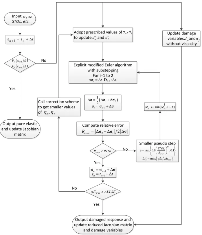
Figure 1 The whole flow of the auto-adaptive algorithm.
5. Numerical modelling
5.1 Material properties and boundary conditions
- 10 -
The mechanical properties of the composite are primarily determined by the properties of the fibre and matrix, but are also influenced by the manufacturing method, i.e. the quality of the bonding interface. In this paper, the material parameters required in the constitutive model were determined by using the aforementioned homogenization method and ROM. The material properties utilized in the numerical modelling are listed in Table 1. Despite the absence of some specifications of the fibre and matrix, the mechanical properties of the fibre and matrix can be evaluated from the static properties of the composite through numerical modelling. The fracture energies of the fibre and matrix were estimated to be 12.5 N/m and 1 N/m, respectively [33]. The viscosity parameters for the fibre and matrix were selected as 0.001 and 0.005, respectively [39]. The load was applied at the centre of the specimen vertically downwards, while the specimen was placed on two supports with a span of 32mm. The contact between the supports and the bottom surface was modelled as a “hard contact” and sliding at the contact point was allowed.
Throughout the numerical test, displacements in the other two principal directions were constrained. The layout of the model is illustrated in Figure 2.
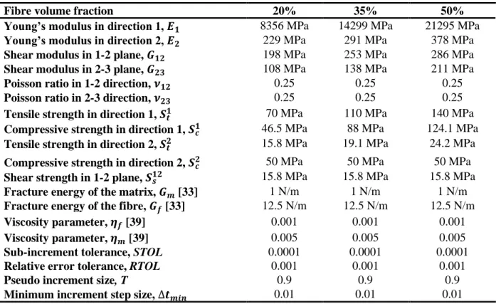
Table 1 Material properties input in the numerical modelling. Direction 1 in the table means the fibre direction, and direction 2 and 3 are the two directions perpendicular to the fibre direction.
Fibre volume fraction 20% 35% 50%
Young’s modulus in direction 1, 𝑬𝟏 8356 MPa 14299 MPa 21295 MPa Young’s modulus in direction 2, 𝑬𝟐 229 MPa 291 MPa 378 MPa
Shear modulus in 1-2 plane, 𝑮𝟏𝟐 198 MPa 253 MPa 286 MPa
Shear modulus in 2-3 plane, 𝑮𝟐𝟑 108 MPa 138 MPa 211 MPa
Poisson ratio in 1-2 direction, 𝝂𝟏𝟐 0.25 0.25 0.25
Poisson ratio in 2-3 direction, 𝝂𝟐𝟑 0.25 0.25 0.25
Tensile strength in direction 1, 𝑺𝒕𝟏 70 MPa 110 MPa 140 MPa Compressive strength in direction 1, 𝑺𝒄𝟏 46.5 MPa 88 MPa 124.1 MPa Tensile strength in direction 2, 𝑺𝒕𝟐 15.8 MPa 19.1 MPa 24.2 MPa Compressive strength in direction 2, 𝑺𝒄𝟐 50 MPa 50 MPa 50 MPa Shear strength in 1-2 plane, 𝑺𝒔𝟏𝟐 15.8 MPa 15.8 MPa 15.8 MPa Fracture energy of the matrix, 𝑮𝒎 [33] 1 N/m 1 N/m 1 N/m Fracture energy of the fibre, 𝑮𝒇 [33] 12.5 N/m 12.5 N/m 12.5 N/m
Viscosity parameter, 𝜼𝒇 [39] 0.001 0.001 0.001
Viscosity parameter, 𝜼𝒎 [39] 0.005 0.005 0.005
Sub-increment tolerance, STOL 0.0001 0.0001 0.0001
Relative error tolerance, RTOL 0.001 0.001 0.001
Pseudo increment size, T 0.9 0.9 0.9
- 11 -
Figure 2 (a) Illustration of the coordinate system; (b) layout of the three-point bending.
5.2 Mesh sensitivity analysis
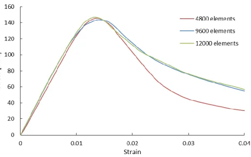
A suitable mesh size needs to be determined to achieve a balance between computational efficiency and model accuracy. Figure 3 shows the variations in stress-strain curve obtained using different mesh densities. It shows that the initial stiffness is negligibly affected by the mesh density, however there are clear differences between the three mesh densities once failure has initiated. The coarse mesh (4800 elements) does not predict as close result as other two meshes, while the finest mesh (12000 elements) generates quite a close result with the intermediate mesh but requires more computation cost. Upon a balance between the computation efficiency and accuracy, 9600 elements (global size 0.25) was selected for the numerical simulations in the following sections.
- 12 -
5.3 Numerical results and discussion
5.3.1 Sensitivity analysis of tensile and compressive strength
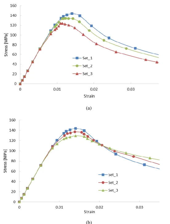
In three-point bending, the top surface of the specimen is under compression while the bottom surface is under tension. From experimental studies, the top surface of the specimen suffered the most damage [45], and thus the compressive strength in the fibre direction is assumed to be significant. On the other hand, the tensile strength in the fibre direction is more important in the bottom surface area. In order to investigate the pattern that the tensile and compressive strength in the fibre direction affect the flexural strength, two groups of numerical experiments were carried out. In these numerical experiments, the tensile and compressive strength in the fibre direction of the composite were varied, while the other material parameters remained the same. The intermediate FVF (35%) was selected as the reference case. The controlled material properties are listed in Table 2 and Table 3.
Table 2 Material properties utilized in the numerical simulations on the influence of the compressive strength in fibre direction.
Set-1 (MPa) Set-2 (MPa) Set-3 (MPa)
Tensile strength in direction 1, 𝑺𝒕𝟏 110 110 110
Compressive strength in direction 1, 𝑺𝒄𝟏 88 75 60
Table 3 Material properties utilized in the numerical simulations on the influence of the tensile strength in fibre direction.
Set-1 (MPa) Set-2 (MPa) Set-3 (MPa)
Tensile strength in direction 1, 𝑺𝒕𝟏 110 95 80
Compressive strength in direction 1, 𝑺𝒄𝟏 88 88 88
- 13 - (a)
(b)
Figure 4 Sensitivity study of the numerically predicted flexural strength of the composites, 35% FVF: (a) the influence of the compressive strength; (b) the influence of the tensile strength.
- 14 -
of numerical simulations showed the influence of the tensile and compressive strength in the fibre
direction. The compressive strength in the fibre direction affected the performance of the composite more significantly than the tensile strength. The later sections reveal that the top surface of the composite was the most vulnerable under three-point bending, and the damage was initiated from the top surface. The composite properties can be managed according to actual needs, for instance, increasing either the
compressive or tensile strength of the composite can improve the flexural strength, whereas increasing the compressive strength can improve the failure strain at the same time. Understanding of how the
components influence the overall performance of the composite can, in return, offer guidance to the manufacturing of the composite.
5.3.2 Damage variables of the fibre
𝒅
𝒇and matrix
𝒅
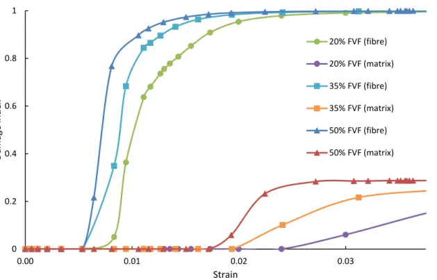
𝒎Investigation of the damage onset and evolution in the fibre and matrix is presented in this section. Figure 5 shows the damage variables for the fibre and matrix of the composites with different FVF. The damage initiation and evolution in the middle of the top surface was presented, which was the compressed area. The damage in the fibre initiated ahead of the matrix, however, the gap decreased with increasing FVF. For composite with 20% FVF, the damage in the matrix initiated at the strain about 0.025, whilst it was about 0.020 when the FVF was 35%, and it was about 0.018 when FVF was 50%. Unlike in the matrix, damage in the fibre initiated at nearly the same strain for all three composite about 0.060. Fibre damage evolved more significantly with increasing strain for composites with higher FVF. As shown that when the failure of the sample occurred the damage index of the matrix had not accumulated to 1 while the index of the fibre had reached 1, which indicated that the fibre damage accumulation was the primary driver of the composite flexural failure.
Figure 5 The damage initiation and evolution in the fibre and matrix for composites with different FVF.
0 0.2 0.4 0.6 0.8 1
0.00 0.01 0.02 0.03
Damage
in
d
ex
Strain
20% FVF (fibre)
20% FVF (matrix)
35% FVF (fibre)
35% FVF (matrix)
50% FVF (fibre)
- 15 -
5.3.3 Numerical model validation
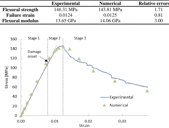
Figure 6 compares the stress-strain curve obtained from the FE analysis with the experimental data, for composite with 35% FVF. A good agreement between the experimental data and numerical results was achieved, with the relative errors for the flexural modulus, flexural strength and failure strain being less than 3% (see Table 4). In the first stage of the experiment, the specimen was in the elastic regime, so the experimental stress-strain relationship was linear. The numerical results also demonstrated the linear stress-strain relation in the first stage and the stiffness was in good agreement (3.0% relative error) with the experimental data. The softening initiation at the end of the elastic regime of the specimen was caused by the damage onset in the specimen, as marked in Figure 6. The second stage of the stress-strain
relationship was from the damage onset to the flexural strength. In this stage, the specimen had not yet failed, but damage accumulation softened the response of the specimen. The remaining curve representing the third stage, which described the mechanical behaviour of the specimen post failure. In Figure 6, the numerical flexural strength (143.81 MPa) agreed well with the experimental data (146.31 MPa). The agreement of the flexural strength between the numerical results and the experimental data showed the accuracy (relative error 1.71%) of the constitutive model in simulating the flexural strength of the specimen in three-point bending. Moreover, the failure strain in numerical results was 0.0125, which was in excellent agreement (relative error 0.81%) with the experimental data, 0.0124.
Table 4 Comparison of the numerical results with experimental data, 35% FVF.
Experimental Numerical Relative errors (%) Flexural strength
Failure strain Flexural modulus
146.31 MPa 0.0124 13.65 GPa
143.81 MPa 0.0125 14.06 GPa
1.71 0.81 3.00
- 16 -
- 17 -
(a)
(b)
(c)
(d)
Figure 7 The damage status of the specimen at the onset of matrix damage, applied vertical displacement 1.2mm, 35% FVF: (a) Damage index contour for the fibre when damage onset is detected in the fibre; (b) Damage status for the matrix when damage onset is detected in the fibre; (c) Damage index contour for the fibre when damage onset is detected in the matrix; (d) Damage index contour for the matrix when damage onset is detected in the matrix.
Damage onset
- 18 -
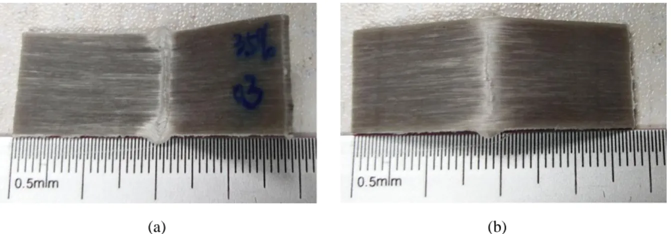
(a) (b)
Figure 8 Failed sample after three-point bending, 35% FVF: (a) the top surface; (b) the bottom surface.
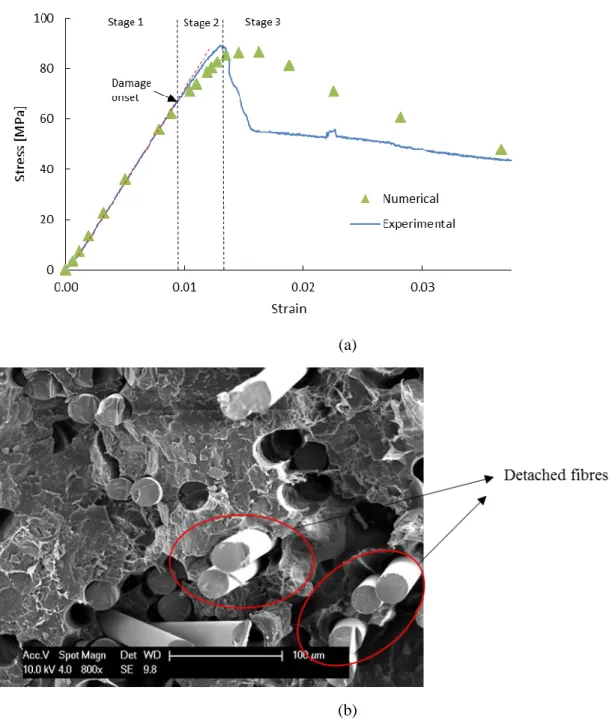
Figure 9 (a) shows a comparison of the numerical results and the experimental data for a specimen with a FVF of 20%. It can be seen that the numerical results agreed well with the experimental data in the elastic region (relative error 1.79%) and the flexural strength was within 1.0% of the experimental data.
However, there was relatively poor agreement in the failure strain (relative error 5.84%) and a mismatch in the post-damage region (see Table 5). Damage propagation appeared to be more sudden according to the experimental curve, with a dramatic reduction in stress at a strain of 0.014. The numerical data indicated a more progressive reduction in strength beyond the ultimate strength. The SEM in Figure 9 (b) shows that there were many detached fibres after failure occurred. The detached fibres lost the reinforcing ability and, hence, reduced the stiffness of the composite dramatically post failure. The reduction in stiffness was therefore due to debonding rather than fibre fracture. However, for the numerical result, the reduction in stiffness was associated with fibre damage accumulation rather than interfacial failure, which had been overlooked in the current model since a perfect fibre/matrix bond had been assumed.
Table 5 Comparison of the numerical results with experimental data, 20% FVF.
Experimental Numerical Relative errors (%) Flexural strength
Failure strain Flexural modulus
88.65 MPa 0.0137 6.69 GPa
87.76 MPa 0.0145 6.81 GPa
- 19 - (a)
(b)
Figure 9 (a) Comparison between the numerical results and experimental results of the composite, 20% FVF; (b) The detached fibres in the failed composite, 20% FVF.
- 20 -
were more common to find in composites with high FVF. Once the specimen had failed, these dry bundles could slide more easily at higher applied strains.
Table 6 Comparison of the numerical results with experimental data, 50% FVF.
Experimental Numerical Relative errors (%) Flexural strength
Failure strain Flexural modulus
192.80 MPa 0.0124 17.33 GPa
189.45 MPa 0.0135 16.53 GPa
1.74 8.87 4.44
(a)
(b)
- 21 -
6. Conclusions
In this paper, a constitutive model from the literature based on Linde’s criterion was adopted to simulate the stress-strain relationship of a fully bio-resorbable composite under three-point bending. Two viscosity parameters were used to regularize the damage variables, hence to improve the convergence, along with an auto-adaptive algorithm to control the incremental step size. The FE model was capable of outputting the damaged stress-strain relationship of the composite and the damage onset and evolution in the fibre and matrix individually. Comparisons between the numerical results and experimental data indicated that
1. The FE model was capable of predicting the behaviour of the composite under three-point bending. The elastic stage of the stress-strain relation predicted by the FE model was in excellent agreement with the experimental data (less than 4.5% relative error in all cases).
2. The absolute flexural strength of the composite was predicted within 2% for all of the FVF studied (20%, 35% and 50%). The prediction of failure strain was relative poor, within 9% of the experimental values, since the model neglected fibre debonding.
3. The sensitivity analysis revealed that both the tensile and compressive strength in the fibre direction of the composite affects the flexural strength. The fibre compressive strength also affected the composite failure strain, but the fibre tensile strength did not.
4. The investigation on the individual damage onset and evolution in the fibre and matrix showed that both damages were initiated from the top then propagated to the bottom, however, the damage in the fibre was initiated prior to that in the matrix. It was noted that the main driver of the composite failure under three-point bending was the damage accumulation in the fibre.
However, the model presented in this paper has defects in predicting the post peak stress-strain
relationship for FVF of 20% and 50% comparing with the prediction for FVF of 35%. A more thorough model should be built in the future based on the current one to consider the fibre debonding and the formation of dry fibre bundles, such that to overcome the defects.
Acknowledgement
The authors would like to acknowledge support received from the International Doctoral Innovation Center (IDIC) at the University of Nottingham Ningbo China.
References
1. Engh, C.A., J. Bobyn, and A.H. Glassman, Porous-coated hip replacement. The factors governing
bone ingrowth, stress shielding, and clinical results. Bone & Joint Journal, 1987. 69(1): p. 45-55.
2. Huiskes, R., H. Weinans, and B. Van Rietbergen, The relationship between stress shielding and
bone resorption around total hip stems and the effects of flexible materials. Clinical orthopaedics
and related research, 1992. 274: p. 124-134.
3. Nagels, J., M. Stokdijk, and P.M. Rozing, Stress shielding and bone resorption in shoulder
arthroplasty. Journal of shoulder and elbow surgery, 2003. 12(1): p. 35-39.
4. Parsons, A.J., et al., Phosphate Glass Fibre Composites for Bone Repair. Journal of Bionic Engineering, 2009. 6(4): p. 318-323.
5. Casteleyn, P., F. Handelberg, and P. Haentjens, Biodegradable rods versus Kirschner wire fixation
of wrist fractures. A randomised trial. Journal of Bone & Joint Surgery, British Volume,
- 22 -
6. van Manen, C.J., et al., Bio-resorbable versus metal implants in wrist fractures: a randomised
trial. Archives of Orthopaedic and Trauma Surgery, 2008. 128(12): p. 1413.
7. Törmälä, P., T. Pohjonen, and P. Rokkanen, Bioabsorbable polymers: materials technology and
surgical applications. Proceedings of the Institution of Mechanical Engineers, Part H: Journal of
Engineering in Medicine, 1998. 212(2): p. 101-111.
8. Hoffmann, J., et al., A totally bioresorbable fibrillar reinforced composite system: structure and
properties. International Journal of Polymeric Materials, 2001. 50(3-4): p. 469-482.
9. Chen, M., et al., In-situ polymerisation of fully bioresorbable polycaprolactone/phosphate glass
fibre composites: In vitro degradation and mechanical properties. Journal of the Mechanical
Behavior of Biomedical Materials, 2016. 59: p. 78-89.
10. Felfel, R.M., et al., Cytocompatibility, degradation, mechanical property retention and ion
release profiles for phosphate glass fibre reinforced composite rods. Materials Science and
Engineering: C, 2013. 33(4): p. 1914-1924.
11. Bitar, M., et al., Soluble phosphate glasses: in vitro studies using human cells of hard and soft
tissue origin. Biomaterials, 2004. 25(12): p. 2283-2292.
12. Parsons, A., et al., Synthesis and degradation of sodium iron phosphate glasses and their in vitro
cell response. Journal of Biomedical Materials Research Part A, 2004. 71(2): p. 283-291.
13. Felfel, R., et al., In vitro degradation, flexural, compressive and shear properties of fully
bioresorbable composite rods. Journal of the mechanical behavior of biomedical materials, 2011.
4(7): p. 1462-1472.
14. Liu, X., et al., Magnesium coated bioresorbable phosphate glass fibres: investigation of the
interface between fibre and polyester matrices. BioMed research international, 2013. 2013.
15. Sharmin, N., et al., Structure, viscosity and fibre drawing properties of phosphate-based glasses:
effect of boron and iron oxide addition. Journal of Materials Science, 2016. 51(16): p. 7523-7535.
16. Mannocci, F., M. Sherriff, and T.F. Watson, Three-Point Bending Test of Fiber Posts. Journal of Endodontics, 2001. 27(12): p. 758-761.
17. Steeves, C.A. and N.A. Fleck, Collapse mechanisms of sandwich beams with composite faces and
a foam core, loaded in three-point bending. Part II: experimental investigation and numerical modelling. International Journal of Mechanical Sciences, 2004. 46(4): p. 585-608.
18. Harper, L.T., et al., Finite element modelling of the flexural performance of resorbable phosphate
glass fibre reinforced PLA composite bone plates. Journal of the Mechanical Behavior of
Biomedical Materials, 2012. 15(Supplement C): p. 13-23.
19. Mishnaevsky Jr, L. and P. Brøndsted, Micromechanical modeling of damage and fracture of
unidirectional fiber reinforced composites: A review. Computational Materials Science, 2009.
44(4): p. 1351-1359.
20. Tserpes, K., et al., Strength prediction of bolted joints in graphite/epoxy composite laminates. Composites Part B: Engineering, 2002. 33(7): p. 521-529.
21. Lu, J., W. Sun, and A. Becker, Material characterisation and finite element modelling of cyclic
plasticity behaviour for 304 stainless steel using a crystal plasticity model. International Journal
of Mechanical Sciences, 2016. 105: p. 315-329.
22. Lu, J., et al., Simulation of the fatigue behaviour of a power plant steel with a damage variable. International Journal of Mechanical Sciences, 2015. 100: p. 145-157.
23. Hill, R. A theory of the yielding and plastic flow of anisotropic metals. in Proceedings of the Royal
Society of London A: Mathematical, Physical and Engineering Sciences. 1948. The Royal Society.
24. Tsai, S.W., Strength Characteristics of Composite Materials. 1965, Philco Corp Newport Beach CA.
- 23 -
26. Matzenmiller, A., J. Lubliner, and R.L. Taylor, A constitutive model for anisotropic damage in
fiber-composites. Mechanics of Materials, 1995. 20(2): p. 125-152.
27. Hashin, Z., Fatigue failure criteria for unidirectional fiber composites. ASME, Transactions, Journal of Applied Mechanics, 1981. 48: p. 846-852.
28. Xu, K. and X.W. Xu, Finite element analysis of mechanical properties of 3D five-directional
braided composites. Materials Science and Engineering: A, 2008. 487(1): p. 499-509.
29. Zhou, Y., Z. Lu, and Z. Yang, Progressive damage analysis and strength prediction of 2D plain
weave composites. Composites Part B: Engineering, 2013. 47: p. 220-229.
30. Fang, G., et al., Investigation on the compressive properties of the three dimensional
four-directional braided composites. Composite Structures, 2011. 93(2): p. 392-405.
31. Murakami, S., Notion of continuum damage mechanics and its application to anisotropic creep
damage theory. ASME, Transactions, Journal of Engineering Materials and Technology, 1983.
105: p. 99-105.
32. Linde, P., et al. Modelling and simulation of fibre metal laminates. in ABAQUS Users’ conference. 2004.
33. Lu, Z., B. Xia, and Z. Yang, Investigation on the tensile properties of three-dimensional full
five-directional braided composites. Computational Materials Science, 2013. 77: p. 445-455.
34. Wang, C., et al., Development of a new constitutive model considering the shearing effect for
anisotropic progressive damage in fiber-reinforced composites. Composites Part B: Engineering,
2015. 75: p. 288-297.
35. Castellano, A., et al., Mechanical characterization of CFRP composites by ultrasonic immersion
tests: Experimental and numerical approaches. Composites Part B: Engineering, 2014.
66(Supplement C): p. 299-310.
36. Mortazavian, S. and A. Fatemi, Effects of fiber orientation and anisotropy on tensile strength and
elastic modulus of short fiber reinforced polymer composites. Composites Part B: Engineering,
2015. 72(Supplement C): p. 116-129.
37. Barbero, E.J., Finite element analysis of composite materials using AbaqusTM. 2013: CRC press. 38. Gao, X., et al. Numerical interpretation of fully bio-resorbable glass fibre reinforced composites.
in International Conference on Composite Materials 21 (ICCM-21). 2017. Xi'an, China. 39. Lapczyk, I. and J.A. Hurtado, Progressive damage modeling in fiber-reinforced materials.
Composites Part A: Applied Science and Manufacturing, 2007. 38(11): p. 2333-2341.
40. Sadighi, M., et al., Experimental and numerical investigation of metal type and thickness effects
on the impact resistance of fiber metal laminates. Applied Composite Materials, 2012. 19(3-4):
p. 545-559.
41. Manual, A.U., Version 6.10. ABAQUS Inc, 2010.
42. Guinea, G.V., J. Planas, and M. Elices, Measurement of the fracture energy using three-point
bend tests: Part 1—Influence of experimental procedures. Materials and Structures, 1992. 25(4):
p. 212-218.
43. Lions, J.L. and G. Duvaut, Inequalities in mechanics and physics. 1976: Springer.
44. Abbo, A., Finite element algorithms for elastoplasticy and consolidation. 1997, University of Newcastle Upon Tyne.
45. Shibata, S., Y. Cao, and I. Fukumoto, Flexural modulus of the unidirectional and random
composites made from biodegradable resin and bamboo and kenaf fibres. Composites Part A: