UNIVERSITI TEKNIKAL MALAYSIA MELAKA
THE DEVELOPMENT OF DIRECTIONAL CONTROL AND
WHEEL SYNCHRONIZATION OF VEHICLE STEERING BY
WIRE (VSBW) SYSTEM BY IMPLEMENTING FUZZY PID
CONTROLLER (FPC)
This report submitted in accordance with requirement of the Universiti Teknikal Malaysia Melaka (UTeM) for the Bachelor Degree of Electrical Engineering
Technology (Industrial Automation & Robotics) (Hons.)
by
MUHAMAD AZIDI BIN MOHD NASIR B071310271
910613-08-5135
UNIVERSITI TEKNIKAL MALAYSIA MELAKA
BORANG PENGESAHAN STATUS LAPORAN PROJEK SARJANA MUDA
TAJUK: The Development of Directional Control and Wheel Synchronization of Vehicle
Steering By Wire (VSBW) System By Implementing Fuzzy PID Controller (FPC)
SESI PENGAJIAN: 2016/2017 Semester 2 Saya MUHAMAD AZIDI BIN MOHD NASIR
mengaku membenarkan Laporan PSM ini disimpan di Perpustakaan Universiti Teknikal
Malaysia Melaka (UTeM) dengan syarat-syarat kegunaan seperti berikut:
1. Laporan PSM adalah hak milik Universiti Teknikal Malaysia Melaka dan penulis. 2. Perpustakaan Universiti Teknikal Malaysia Melaka dibenarkan membuat salinan untuk
tujuan pengajian sahaja dengan izin penulis.
3. Perpustakaan dibenarkan membuat salinan laporan PSM ini sebagai bahan pertukaran antara institusi pengajian tinggi.
4. **Sila tandakan ( )
SULIT
TERHAD
TIDAK
(Mengandungi maklumat yang berdarjah keselamatan atau
kepentingan Malaysia sebagaimana yang termaktub
dalam AKTA RAHSIA RASMI 1972)
(Mengandungi maklumat TERHAD yang telah ditentukan
oleh organisasi/badan di mana penyelidikan dijalankan)
(________________________)
Alamat Tetap:
NO 263, LRG MUTIARA 4,
TAMAN INTAN MUTIARA, 36000,
TELUK INTAN, PERAK D. R.
Disahkan oleh:
(_________________________)
Cop Rasmi:
DECLARATION
I hereby, declared this report entitled “The Development of Directional Control and Wheel Synchronization of Vehicle Steering by Wire (VSBW) system by implementing Fuzzy PID Controller (FPC)” is the result of my own research except as cited in references.
Signature :………
Name : MUHAMAD AZIDI BIN MOHD NASIR
APPROVAL
This report is submitted to the Faculty of Engineering Technology of UTeM as a partial fulfillment of the requirements for the degree of Bachelor Degree of Electrical Technology Engineering (Industrial Automation & Robotics) with Honours. The member of the supervisory and co-supervisor is as follow:
………. (En. Mohd Zaidi Bin Mohd Tumari)
……….
i
ABSTRAK
ii
ABSTRACT
iii
DEDICATION
iv
ACKNOWLEDGEMENT
Firstly, I would like to praise to ALLAH that give me strength and patience to complete my PSM that is to develop Vehicle Steering by Wire (VSBW) control system. Secondly, I would like to thanked my PSM supervisor MR. MOHD ZAIDI BIN MOHD TUMARI and MR. MUHAMMAD SHAHRANI BIN JOHAL who help me a lot from the start of this project until it finished. Then I would like to thanked my parent, brothers, sister, close friend and classmate that always pray for my success. I also would like to thanked to other lecturers that help contribute ideas when a problem a rise. Lastly I would like to say thank you to Nur Azmina Izzati binti Ab Rahim for supporting me and give me inspiration throughout this project. Thank you again and
v
TABLE OF CONTENT
Abstrak i
Abstract ii
Dedication iii
Acknowledgment iv
Table of Content
v-vii List of Table viii
List of Figures ix-x CHAPTER 1: INTRODUCTION 1
1.0 Background 1
1.1 Problem Statement 2
1.2 Objectives 2
1.3 Scope of Project 3
1.4 Thesis Outlines 3 CHAPTER 2: LITERATURE REVIEW 4
2.0 Introduction Literature Riview 4
2.1 Related Work 4
2.1.1 PID controller with feedforward variable steering ratio 4-5 2.1.2 Virtual sensing to estimate vehicle yaw rate by only 5-6
measuring the articulation angle and vehicle speed
2.1.3 Adaptive on-line parameter identification model 6 reference control (MRC) strategy.
2.1.4 Robust sensor fault detection and isolation based on sliding 7 mode observer.
vi 2.1.6 Handling safety improvement for Steer-By-Wire Using Fuzzy 8 Controller
2.1.7 Incremental Fuzzy Expert PID control 9
CHAPTER 3: METHODOLOGY 10
3.0 Introduction 10
3.1 Project Flow Chart 10-11
3.2 Modelling of vehicle steer by wire (VSBW) system 12 3.2.1 Vehicle steer by wire(VSBW) steering wheel system 12 3.2.2 Vehicle steer by wire(VSBW) front wheel system 13 3.2.3 Mathematical modelling of steering wheel system 13- 14 3.2.4 Mathematical modelling of front wheel system 14-15 3.2.5 Parameter used in this mathematical modelling equation 15
3.3 PID controller techniques 16
3.3.1 Objectives PID control 16
3.3.2 PID control procedures in closed loop system 16-17
3.3.3 PID controller characteristic 18
3.3.4 Ziegler-Nichols frequency response method 18-20
3.4 Fuzzy logic controller 21
3.4.1 Fuzzy logic controller basic procedure 21-22
3.5 Electrical hardware review 23
3.5.1 National Instrument Myrio 23
3.5.2 30A DC Motor Driver 24
3.5.3 120W DC brush motor 25
3.5.4 Rotary Encoder B-106-239832 26
3.5.5 Enhanced SmartDrive40 27
3.6 Mechanical Design for VSBW system 28-29
CHAPTER 4: RESULT & DISCUSSION 30
4.0 Introduction 30
vii 4.2 VSBW hardware using LABVIEW software 32-33 4.3 Experiment for PD-PID controller in LabVIEW 34 4.3.1 Step response with single and multiple set point/reference 34-35
4.3.2 Front wheel response to the steering wheel input 36-37
4.3.3 Returnability of the steering wheel 37-38 4.4 Experiment for Fuzzy PID controller in LabVIEW 38 4.4.1 Fuzzy Logic Controller (Tuning) 38-41 4.5 Returnability of the steering wheel using Fuzzy Logic Controller 41-42 4.6 Comparison between PD-PID controller and Fuzzy PID controller 42
CHAPTER 5: CONCLUSION AND RECOMMENDATION 43
5.0 Introduction 43
5.1 Summary of VSBW System Research 43
5.2 Significant of VSBW System Research 43
5.3 Problem Faced During VSBW System Research 44
5.4 Recommendation for Future Improvement 44
REFERENCES 45-46
viii
LIST OF TABLES
3.1 Parameter of mathematical modelling 15
3.2 Characteristics of P, I, D controllers 18
3.3 Critical gain (Kcr) and Critical period (Pcr) 19
3.4 Calculation of PID controller based on Ziegler Nichols 20
4.1 Range of membership function of Input 39
4.2 Range of membership function of error 39
4.3 Range of membership function output angle 40
4.4 Rules base 41
ix
LIST OF FIGURES
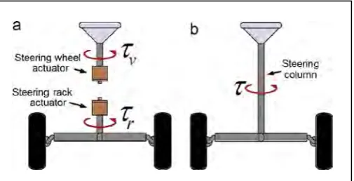
1.1 (a) VSBW (b)Conventional Steering System 1
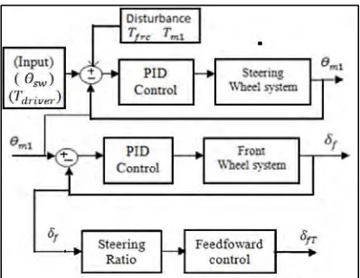
2.1 Block diagram of VSBW with steering ratio and feedforward controller 6
2.2 Block diagram of steering system 7
2.3 Block diagram for control(MRC) strategy 7
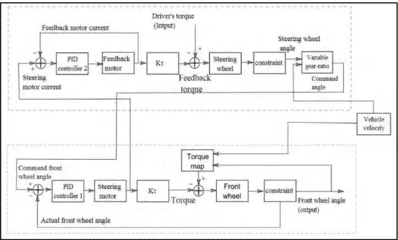
2.4 Block diagram for upper control circle and lower control circle 9
3.1 Project Flow Chart 11
3.2 steering wheel system diagram [1] 12
3.3 front wheel system diagram [1] 13
3.4 Block Diagram for PID controller 16
3.5 Step response for Critical Period (1cycle) 19
3.6 Constant oscillation response 20
3.7 Basic Configuration of Fuzzy logic 21 3.8 Configuration of Fuzzy logic in MATLAB 22
3.9 Membership function shape for input 22
3.10 Membership function for output. 22
3.11 MYRIO 24
3.12 30A DC motor driver 25
3.13 120W DC brush motor 25
x 3.15 Enhanced SmartDrive40 27
3.16 Rear view of steering wheel system 28
3.17 Side view of steering wheel system 28
3.18 Top view of front wheel system 29
3.19 Front view of front wheel system 29
3.20 Side view of front wheel system 29
4.1 Block diagram for VSBW system 31
4.2 Step response for 𝜃𝑠𝑤 and 𝛿𝑓 31
4.3 Step response for 𝜃𝑠𝑤 and 𝛿𝑓 with disturbance 32
4.4 Front Panel of VSBW in LabVIEW 33
4.5 Control design for VSBW 33 4.6 PD controller block diagram for steering wheel system in LabVIEW 34
4.7 PID controller block diagram for front wheel system in LabVIEW 34
4.8 Step respond of VSBW system using one set point 35 4.9 Step respond of VSBW system using multiple set point 35 4.10 Front wheel angle from constant steering wheel input (60 to -100 degree) 36 4.11 Front wheel angle from continuous steering wheel input 37 4.12 Steering wheel returnability step response graph 37
4.13 Fuzzy Logic Controller Block Diagram in LabVIEW 38
4.14 First Membership function (Input) 38
4.15 second input membership function (error) 39
4.16 Output membership function (output angle) 40
4.17 Test system 41
1
CHAPTER 1
INTRODUCTION
1.0 Background
[image:15.595.208.461.475.604.2]The conventional way steering method for vehicle is the mechanical connection between the steering wheel and the front wheels. This mechanical contains many components such as steering shaft, column, gear reduction mechanism, etc. Nowadays, vehicle steer by wire (VBSW) system has been one of interesting research because of its major features that is to remove as many mechanical components as possible. The VSBW system is expected to give more advantages than the conventional steering method such as simplicity of control, low cost, etc. The conventional method of steering and the VSBW system is shown in Figure 1 [1].
2
1.1 Problem Statement
VSBW system expected not only implement same function as conventional mechanical coupling steering system, but it expected to provide advanced steering function. The front wheel needs to follow the input from the driver precisely. But in the real situation, the vehicle SBW system is faced many disturbances such as uneven condition of the road and parameter uncertainties of the system. Therefore, a more robust control system for VSBW system need to be develop.
1.2 Objective
The objectives of this project are:
i. To design the Fuzzy PID control schemes for controlling the direction and synchronization of the front wheel in vehicle SBW system.
ii. To develop complete simulation and experimental verification for VSBW system.
iii. To analyze the performances of the control schemes in terms of wheel directional and synchronization control, time response specifications and robustness to parameter uncertainty.
1.3 Project Scope
3 system and interface between hardware and software. MYRIO and LABVIEW software is used for the interface between hardware and software.
1.4 Thesis Outlines
There are five chapters in this thesis. The first chapter is an introduction to the thesis. The second chapter is literature review, which basically a review on others work or projects that are related to this project. The third chapter is about what method is used and been implement to complete this project. The fourth chapter will discuss the result. Lastly chapter five will conclude the project and discuss the recommendation.
Chapter 1: In chapter 1, currently brief about general ideas of the project
which are introduction, problem statement, target of the project, scope of project, project significant and thesis outlines.
Chapter 2: This chapter is about literature review which is to study and
compare the work or journal that related with the project. This is important in order to obtain some knowledge about the project.
Chapter 3: Chapter 3, will be discuss about methodology, which is consists
flowchart of whole project and the description of component that will used to solve the problem statement.
Chapter 4: Chapter 4, will be discuss about the result of the project that have
been done in order to achieve the objective.
Chapter 5: Chapter 5, will discuss about conclusion and recommendation for
4
CHAPTER 2
LITERATURE REVIEW
2.0 Introduction Literature Review
This chapter will discuss about all related information and study about project
to achieve the project aims. This chapter involves research and find the information about the concept of VSBW system that has been done and related to this project.
2.1 Related Work
There are some of journals that are talk about vehicle steer by wire system(VSBW) and the method they used for the system. These journals are used as a reference to complete this project.
2.1.1 PID controller with feedforward variable steering ratio
5 Figure 2.1: Block diagram of VSBW with steering ratio and
feedforward controller
2.1.2 Virtual sensing to estimate vehicle yaw rate by only measuring the articulation angle and vehicle speed.
6 Figure 2.2: Block diagram of steering system
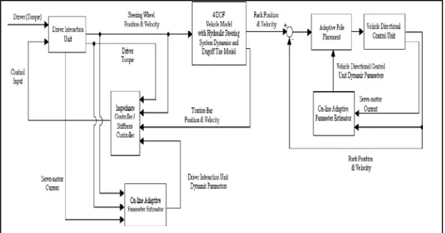
2.1.3 Adaptive on-line parameter identification model reference control (MRC) strategy.
A. Emre Cetin, et al. (2012), method that have been purpose is to uses the external force or torque that is measured as an input reference. From the external force, the output of the system is calculated while the real system is properly controlled to find the system output. The Block diagram of the system is shown in Figure 2.3. Other than that, the adaptive on-line parameter used the output error, equation error and the modified recursive to evaluate the unknown parameter then properly controlled the output system.
[image:20.595.186.508.470.639.2]7
2.1.4 Robust sensor fault detection and isolation based on sliding mode observer.
S.Dhari, et al.(2012), suggest a method that use robust sliding mode observer(H∞) with parametric uncertainties and sensor fault that is based on linear matrix inequalities(LMIs). This method is to improve the previous method that use model based fault detection and isolation, the model based fault detection and isolation method have been proved that in present of disturbance in the parameter will cause the result to be imprecise. Compare to model based fault detection sliding mode observer is more robust and are known for its insensitive nature to an unknown disturbance. Therefore, the sliding mode observer including H∞ performance is design to actively estimate the error of the sensor. To make the design is asymptotically stable an acceptable LMI optimization is calculated.
2.1.5 Bilateral control of vehicle steer by wire system with variable gear ratio
8 Figure 2.4: Block diagram for upper control circle and lower control circle
2.1.6 Handling safety improvement for Steer-By-Wire Vehicle Using Fuzzy Controller
[image:22.595.186.466.70.239.2]N. Elmi, et al. (2011), has proposed a novel controller to improve vehicle handling safety. The novel controller used Fuzzy PID controller with Fuzzy compensator to actively control both front wheel and steering wheel independently. The Fuzzy PID controller used dynamic of nonlinear 8Dof model for simulation purpose. To get the desired yaw rate, the controller is designed base on the steady state steering on the circular path. Then it used feedback for yaw rate angle error and its time derivative side slip angle, lateral acceleration and roll angle to improve its handling safety and roll stability. The control design is shown in Figure 2.5
9 2.1.7 Incremental Fuzzy Expert PID control
10
CHAPTER 3
METHODOLOGY
3.0 Introduction
In this section the methods used to develop vehicle steering by wire (VSBW) system will be described. The method for developing the Fuzzy PID control(FPC) schemes will also be described in this chapter. These methods explained in this chapter are important in order to make sure that the flow of this project will progress without difficulties.
This chapter also will be explaining the software, hardware and experimental development that are used for this project. There are two softwares that are used for this project which are MATLAB and LABVIEW. Therefore, the overall details of method above will be describing in this chapter.
3.1 Project Flow
Flow chart is one of important step in order to smooth the project flow. These