i
UNIVERSITI TEKNIKAL MALAYSIA MELAKA
DEVELOPMENT OF PUBLIC TRANSPORTATION (BUS)
NOTIFICATION USING PIC MICROCONTROLLER
This report submitted in accordance with requirement of the Universiti Teknikal Malaysia Melaka (UTeM) for the Bachelor Degree of Engineering Technology
(Electrical Industry) (Hons.)
by
NURUL AZLIYANA BINTI AZMAN B071310383
911009-01-5442
ii
DECLARATION
I hereby, declared this report entitled “DEVELOPMENT OF PUBLIC
TRANSPORTATION (BUS) NOTIFICATION USING PIC MICROCONTROLLER” is the results of my own research except as cited in references.
Signature :
Author’s Name : NURUL AZLIYANA BINTI AZMAN
iii
APPROVAL
This report is submitted to the Faculty of Engineering Technology of UTeM as a partial fulfillment of the requirements for the degree of Bachelor of Electrical Engineering Technology (Industrial Power) with Honours. The member of the supervisory is as follow:
………
iv
ABSTRAK
v
ABSTRACT
vi
DEDICATION
To my beloved parents and family
vii
ACKNOWLEDGEMENT
First of all, I am grateful to ALLAH because can complete my final year project 1 successfully on time.
I also wish to thank my mother Siti Hawa Binti Hashim and my father Azman Bin MD Said and the whole of my family for prayer and support me in completing this final year project
Also not forget to thank my supervisor Prof Madya Mohd Ariff Bin Mat Hanafiah that had given me with much information, guidance, advices and motivation finish this final year project
viii
TABLE OF CONTENT
Abstrak i
Abstract ii Dedication iii
Acknowledgement iv
Table of Content v List of Tables vi
List of Figures vii List Abbreviations, Symbols and Nomenclatures viii
CHAPTER 1: INTRODUCTION 1
1.1 Project Background 1
1.2 Problem Statement 2
1.3 Objective 3
1.4 Scope 3
1.5 Project Contribution 4
CHAPTER 2: LITERATURE REVIEW 5
2.1 Introduction 5
2.2 Theory and Basic Principles 6
2.2.1 ZigBee Wireless 7
2.2.1.1 History 8
2.2.2 Microcontroller 11
2.2.3 PIC Microcontroller 12
2.2.4 LCD 13
ix
2.2.6 LED 14
2.3 Previous Studies 15
CHAPTER 3 : METHODOLOGY 16
3.1 Introduction 16
3.2 Project Implementation 16
3.2.1 Bus Stop Design 19
3.2.2 Bus Design 21
3.2.3 Components Selection 23
CHAPTER 4 : RESULTS AND OVERVIEW 25
4.1 Results 25
4.2 Project Results 29
CHAPTER 5 : CONCLUSION & RECOMMENDATION 32
5.0 Conclusion 32
5.2 Recommendation 32
REFERENCES 33 APPENDIX 1 35
x
LIST OF TABLES
Table Page
11
[image:11.612.115.534.161.410.2]LIST OF FIGURES
Figure Page
Figure 2.2.1 Zigbee Symbol………7
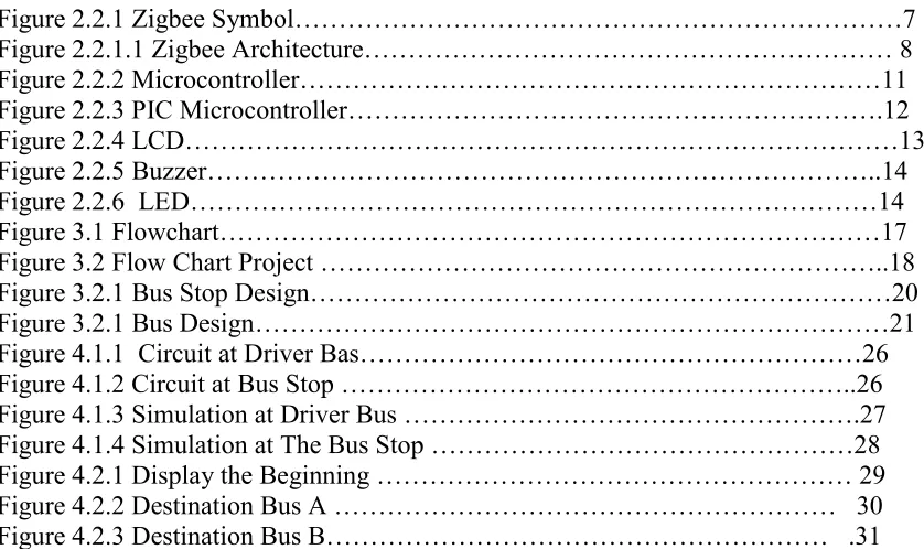
Figure 2.2.1.1 Zigbee Architecture……… 8
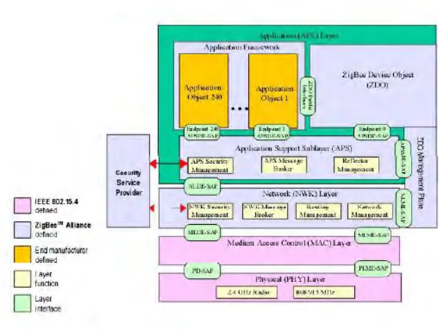
Figure 2.2.2 Microcontroller………11
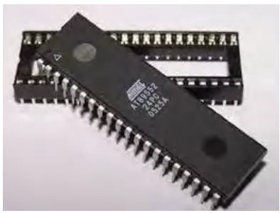
Figure 2.2.3 PIC Microcontroller……….12
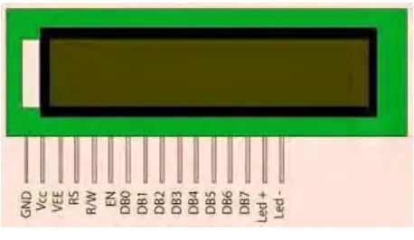
Figure 2.2.4 LCD………13
Figure 2.2.5 Buzzer………..14
Figure 2.2.6 LED………14
Figure 3.1 Flowchart………17
Figure 3.2 Flow Chart Project ………..18
Figure 3.2.1 Bus Stop Design………20
Figure 3.2.1 Bus Design………21
Figure 4.1.1 Circuit at Driver Bas………26
Figure 4.1.2 Circuit at Bus Stop ………..26
Figure 4.1.3 Simulation at Driver Bus ……….27
Figure 4.1.4 Simulation at The Bus Stop ………28
Figure 4.2.1 Display the Beginning ……… 29
Figure 4.2.2 Destination Bus A ……… 30
Figure 4.2.3 Destination Bus B……… .31
12
CHAPTER 1
INTRODUCTION
1.1Project Background
The bus transportation system is the process of transporting passengers from one location to the desired user's location. The rapid technologies and industrial advancements have effectively contributed to produce enormous and efficient transportation methods. The amount of population increases and their need for more transportation systems increase as well.(Koga, 1999)[1] .Not all people are being able to process their own transport and travel individually.
The collectivity transport means are essential to enable people to move around cheaply and reduce the traffic jam on roads. (Koga, 1999)[1]. Bus transportation is an efficient system that allows people to travel to variety of destinations at low cost. Developed countries have implemented various modernized bus transportation systems that enable passengers to freely travel to any desired locations. However, there are some obstacles that encountered by passengers who using bus transportation(Koga, 1999)[1].
13
1.2 Problem statements
Nowadays the need for travelling from place to place is becoming a routine that people almost do every day. There are various transportation systems, in which people can travel from one place to another. Bus transportation is the people's common choice to use due to its availability at low cost and simple travelling methods to the user’s destination.
The disadvantages of using the bus transportation is when there are many passengers want to use it, they could be missing the bus and this makes them unable to reach a destination punctually(Me, 2013)[3]. Moreover, the drivers and transportation vendors waste time and cost by driving a bus to an empty bus station(Koga, 1999)[1]. All these obstacles exist due to the olden and inefficient systems and technologies of bus transportation.
However, these bus transportation system's deficiencies can be mitigated by developing a technology system that can significantly contribute to managing, improving, and modernizing the bus transportation systems. The system utilizes a microcontroller that controls the Zigbee wireless communication module that acts as a communication tool between the bus stations and the buses.
14
1.3 Objectives
The objectives of Public Transportation (BUS) Commuter Notification system are: 1) To design a notification system for bus transportation by using the ZigBee wireless
module.
2) To develop a program for the notification system by using the PIC Microcontroller. 3) To improve the efficiency and reliability of the public bus transportation system.
1.4 Scope
The scope of this project includes designing bus transportation systems utilizing a Zigbee, PIC 16F877A microcontroller, buzzer, and LCD. The Zigbee wireless module is the communication device between the buses and the bus stations. Furthermore, the PIC microcontroller acts as the controlling and processing device that drives the entire system. A programming code will be developed and uploaded into the PIC.
15
1.5 Project Contribution
16
CHAPTER 2
LITERATURE REVIEW
2.1 Introduction
17 The most important is implementing the system for bus transportation, since it enables passengers to move around in convenience and arranged way. As a tourist may not possess an individual transport, bus transportation would make it easier for them to travel to a desired destination. Apart from that, energy consumption could be reduced by utilizing bus transportation where passengers will take collectively transport instead of using individual transport. Hence bus transportation not only convenience to passengers but also contributes in reducing energy consumption and travelling costs as well.
2.2 Theory and basic principle
18
2.2.1 Zigbee Wireless
ZigBee is a specification for a suite of high-level communication protocols used to create personal area networks with a small, low-power for digital radios.The technology defined by the ZigBee specification is intended to be simpler and less expensive than other wireless personal area networks (WPANs), such as Bluetooth or Wi-Fi. Applications include wireless light switches, electrical meters with in home displays, traffic management systems, and other consumer and industrial equipment that require a short-range low rate wireless data transfer(Ke, Ruiqiang, & Cuixia, 2008)[2].
Low power consumption will limit the transmission distances to 10–100 meters depending on power output and environmental characteristics. ZigBee devices can transmit data over long distances by passing data through a mesh network of intermediate devices to reach more than the distance. ZigBee is typically used in low data rate applications that require long battery life and secure networking (ZigBee networks are secured by 128 bit symmetric encryption keys.) ZigBee has a defined rate of 250 Kbit/s, is best suited for intermittent data transmissions from a sensor or input device.
19
2.2.1.1 History
ZigBee was created in 1998 and standardized in 2003, and revised in 2006. The ZigBee standard has evolved since its original release in 2004 and it is a new low cost, low power wireless networking standard for sensors and control devices.
[image:19.612.165.483.355.595.2]ZigBee provides network speeds of up to 250kbps and is expected to be largely used in wireless sensor network applications where high data rates are not required. ZigBee uses the media access to control the layer and physical layer for communication between devices. ZigBee also offers a short-range wireless networking capability with low cost, low data rate and low power consumption.(Kobayashi, 2016)[5]
20 Each layer will perform a specific function in the ZigBee protocol architecture. The data will entity provides the data transmission service and a management entity provides the all other services. Each service entity exposes an interface to the upper layer through a service access point (SAP) and each SAP supports a number of service primitives to achieve the required functionality .The ZigBee protocol will be built upon on this foundation by providing the network layer (NWK) and the framework for the application layer. The application layer framework consists of the application support sub-layer (APS) and the ZigBee device objects (ZDO).
The lower frequency PHY layer covers both of the 868MHz European bands and the 915 MHz band that are used in the United States and Australia. The higher the frequency the more layers are used on virtually worldwide. The responsibilities may also include transmitting frames, synchronization and providing a reliable transmission mechanism. The ZigBee network layer supports star, tree, and mesh network topologies. The ZigBee coordinator is responsible for initiating and maintaining the devices on the star network topology.
22
2.2.2 Microcontroller
A microcontroller is a small computer that uses integrated circuit and it consists of processor core, memory, programmable input and output. Then, microcontrollers were designed for the embedded application that contrast to the microprocessor that is used in the personal computer or the other general-purpose application for various discrete chips. Microcontroller are utilized in the automatic control products and devices, such as the automobile engine control system, implemented medical devices, remote controls, power tools, embedded systems and so on.
[image:22.612.246.443.482.632.2]It will reduce the size of the system compared to the design that use the separate microprocessor, memory, input and output devices. They have combined the signal of the microcontroller that will come to integrate the analog components that need to control the non-digital electronic system. Some of the microcontroller may use the four-bit words and will operate at the clock rate of 4 kHz frequency(Belvedere, Bianchi, Borghetti, & Paolone, 2009)[7].
23
2.2.3 PIC Microcontroller
Peripheral Interface Controller (PIC) is a family of Harvard architecture microcontrollers that was developed by Microchip Technology. They derived the PIC16F887 originally developed by General Instrument's Microelectronics Division. The name PIC initially referred to "Peripheral Interface Controller". The model of PIC had read-only-memory (ROM) or field-programmable EPROM that used for program storage with some erasing memory. The all current models that used Flash memory for program storage and newer models allow PIC to reprogram itself.
[image:23.612.241.450.443.664.2]The program memory and data will be separated. The data memory is 8-bit, 16-bit and in later models, 32-16-bit wide. They are programmed using computer software such MPLAB, C/C++ compilers, and PICKit series. Some parts have in-circuit programming capability that low-cost development programmers are available and have a high-production programmer.
24
2.2.4 LCD
The LCD display will be connected to the output of the bus transportation systems unit. The coding is constructed using embedded C language and is uploaded to the PIC microcontroller using C compiler and LCD's pins are connected to the PIC. LCD display will be using 7-segment display. The advantages of using this LCD are their low cost power consumption, ideal in low power, and come in different shapes and size. The disadvantages of using these materials are battery operated and batteries needed to b replaced when its power is used up.
[image:24.612.213.442.537.670.2]There are two types of LCD connections, parallel LCDs and serial LCDs. Parallel LCDs are connected to the microcontroller I/O ports using 4 or 8 data wires and data is transferred from the microcontroller to the LCD in parallel form. Series LCDs are connected to the microcontroller using only one data line and data are transferred to the LCD using the standard RS232 asynchronous data communication protocols. Series LCDs are easier to use, but they usually cost more than the parallel ones. Serial LCDs also have the advantage that only one wire is required to interface them to a microcontroller, thus saving the I/O pins. In this section, we shall be looking at the interface and programming of both types of LCDs.