White Rose Research Online
[email protected]
Universities of Leeds, Sheffield and York
http://eprints.whiterose.ac.uk/
This is a copy of the final published version of a paper published via gold open access
in Earthquake Engineering & Structural Dynamics.
This open access article is distributed under the terms of the Creative Commons
Attribution Licence (
http://creativecommons.org/licenses/by/3.0
), which permits
unrestricted use, distribution, and reproduction in any medium, provided the
original work is properly cited.
White Rose Research Online URL for this paper:
http://eprints.whiterose.ac.uk/81371
Published paper
Londono, J.M., Wagg, D. and Neild, S.A. (2014) Supporting brace sizing in structures
with added linear viscous fluid dampers: A filter design solution. Earthquake
Published online 7 May 2014 in Wiley Online Library (wileyonlinelibrary.com). DOI: 10.1002/eqe
Supporting brace sizing in structures with added linear viscous fluid
dampers: A filter design solution
Julián M. Londoño
,, David J. Wagg and Simon A. Neild
Department of Mechanical Engineering, University of Bristol, Bristol, BS8 1TR, U.K.
SUMMARY
Viscous fluid dampers have proved to be effective in suppressing unwanted vibrations in a range of engi-neering structures. When dampers are fitted in a structure, a brace is typically used to attach them to the main structure. The stiffness of this brace can significantly alter the effectiveness of the damper, and in structures with multiple dampers, this can be a complex scenario to model. In this paper, we demonstrate that the effects of the brace compliance on the damper performance can be modelled by way of a first-order filter. We use this result to formulate a procedure that calculates the stiffness required by the supporting brace to provide a specified effectiveness of the damping action. The proposed procedure assumes that vis-cous dampers have been sized in a previous design step based on any optimal methodology in which, as is usually the case, the presence of supporting braces and their dynamic effects were neglected. Firstly con-sidering a one degree-of-freedom system, we show that the proposed method ensures a desired level of damper efficiency for all frequencies within a selected bandwidth. Then the analysis is extended to the case of multi-degree-of-freedom systems to show that the design criteria can be applied in a straightforward and successful manner to more complex structures. © 2014 The Authors.Earthquake Engineering & Structural Dynamicspublished by John Wiley & Sons Ltd.
Received 5 July 2013; Revised 21 March 2014; Accepted 24 March 2014
KEY WORDS: brace stiffness; Maxwell model; supplemental damping; brace–damper systems
1. INTRODUCTION
The idea of incorporating damping devices into a structure that can absorb a considerable portion of the vibration energy has been used for many decades [1–3]. A popular solution is based on passive viscous fluid dampers deployed in a wide range of configurations [4–6]. The typical aim is to protect structures from the damaging effects of destructive natural events, while offering reliable supplemental energy dissipation systems at relatively low installation and maintenance cost. This paper focuses on the design of supporting braces for structures provided with linear viscous fluid dampers.
A well-designed system based on viscous fluid damper could effectively mitigate the hazard posed by strong dynamic forces like those generated by wind or seismic loads. Over many years, research efforts have been aimed at reliable and cost-effective design practices. Optimal design methodologies for passive dampers based on a number of theories have been proposed for determining both damper sizes as in [7–11] and damper locations as in [12–15] among others. They commonly differ on how the optimisation problem is addressed and in which cost function and constraints the optimisation problem are subjected to.
Corresponding to: Julián M. Londoño, Department of Mechanical Engineering, University of Bristol, Queens Building, University Walk, Bristol, BS8 1TR, U.K.
E-mail: [email protected]
Nevertheless, most conventional approaches for designing energy dissipation devices do not take into account the presence of supporting braces, whose local compliance can significantly reduce the desired dissipative action of the dampers. This said, work that has acknowledged this problem includes that of Takewaki & Yoshitomi [16], where the authors proposed a damping optimisation procedure by considering the minimisation of the inter-storey drifts evaluated at the undamped fundamental natural frequency. Other relevant studies include those of Parket al.[17] and Singhet al.[18] who describe the use of gradient-based optimisation algorithms to obtain the optimal parameters of dampers and their supporting braces in structures subjected to seismic motions. More recently, Chenet al.[19] also proposed a gradient-based numerical procedure for determining the minimum brace stiffness together with a set of optimal damper coefficients to meet a target response reduction. They used Maxwell model-based brace–damper systems and concluded that a brace stiffness equal to the first storey stiff-ness would be adequate for the desirable levels of response reduction in typical applications. Although optimisation gives solutions, insight into how individual brace stiffnesses affect the overall dissipation is unclear.
As an alternative to complex optimisation, our approach is to use one of the existing damper sizing strategies (where damper coefficients are typically optimised assuming infinitely stiff braces) and then use a filter method to select the stiffness of all braces in a way that the damper efficiency reaches a predetermined specification. The most closely related approach in the literature is that proposed by Fu & Kasai [20], where the influence of brace stiffness was studied through a parametric analysis. The authors concluded that a ratio between the damper parameters and braces stiffness approximately in the range1:0–1:5and a ratio between the braces and storey stiffness in the region of10are recommend-able for near-optimal solutions. However, their formulation is based on the study of the steady-state harmonic motion of an SDOF oscillator fitted with a brace–damper system at its undamped natural frequency only. Another relevant method that uses a transformation from the Kelvin model to the Maxwell model is presented by Valleset al.[21]. This method is formulated for steady-state motion at a single vibration frequency, and its generalisation to a wider frequency range is unclear. In addition, it requires the introduction of a fictitious stiffness in the Kelvin model that is difficult to relate to the physical parameters – as discussed by the authors.
In this paper, we observe that the effects of the brace compliance on the damper performance can be modelled as a first-order filter (or series of filters if multiple dampers are present). Based on this, we propose a new method for selecting brace stiffnesses. Firstly, the viscous dampers are sized in the normal way – using an optimal design methodology that ignores the dynamic effects of supporting brace stiffnesses. Then we use the first-order filter observation to determine the stiffness required by the supporting brace such that the resulting brace–damper assembly will behave with a desired level of efficiency within a predefined frequency bandwidth. By adopting this approach, we believe that this simple method can be used as an additional tool, which is complementary to conventional damper design strategies. To present the method, we first consider a single-degree-of-freedom structure in Section 2. Then, in Section 3, the analysis is extended to the case of multi-degree-of-freedom systems to show that the design criteria can still be applied straightforwardly. In Section 4, we consider two example systems and then conclude in Section 5.
2. BRACE SIZING IN A SINGLE-DEGREE-OF-FREEDOM STRUCTURE
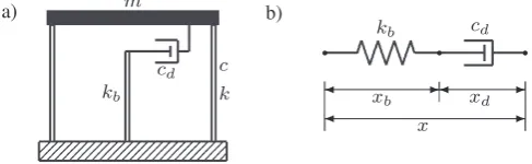
Figure 1. (a) Structure with an added brace–damper system. (b) Maxwell model.
mx.t /R Ccx.t /P Ckx.t /Cfd.t /D mxRg.t / (1a)
fd.t /C
cd
kb P
fd.t /D cdx.t /P (1b)
We calculate the system transfer function for the structural displacement with respect to the ground acceleration. To do so, we use the set of parameters:
!n2D k
mI D c 2m!n
I Dcd
kb
I ˇDcd
m: (2)
Notice that along with the classical definition of undamped natural frequency and structural damping ratio, two parameters,andˇ, are used to represent the ratio of the damper size to the brace stiffness and the ratio of the damper size to the mass of the structure, respectively.
By substituting these parameters into Equation (1), applying the Laplace transform method and taking out common factors, we find
s2C2!nsC!n2
X.s/Cm1Fd.s/D Ag.s/
.1Cs/Fd.s/D ˇmsX.s/
(3)
where s is the Laplace variable and X, Fd and Ag are the Laplace transforms of x, fd andxRg, respectively. By eliminatingFd, we obtain the transfer function
T .s/D X.s/
Ag.s/
Ds2C.2!nCH.s// sC!n2
1
(4)
where
H.s/D ˇ
1Cs: (5)
Note that the brace–damper assembly properties and associated dynamics are fully encapsulated in
H.s/. For the case of an infinitely rigid brace, the parameter becomes zero, and the damper’s contribution can be directly accounted for through the constant parameterˇ.
[image:4.595.177.421.69.144.2]−20 −10 0 10
10−2 10−1 100 101
[image:5.595.180.413.67.261.2]−90 −45 0
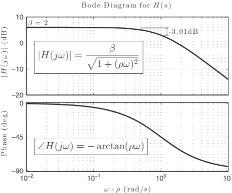
Figure 2. Bode diagram showing the effects of brace–damper assembly on the system dynamics (ˇD2).
2.1. Efficiency of the brace–damper assembly
The compliance of the damper brace will introduce a reduction in the additional damping force effec-tively transferred to the structure as well as a phase shift in the damper response. In common with a first-order filter, both gain and phase shift are a function of the frequency of vibration.
Consider the Bode diagram ofH.s/shown in Figure 2. The equations for obtaining magnitude and phase are embedded in each plot. When the system vibrates at an angular frequency ! D 1, the magnitude of H.s/, that is, the effective damping force supplied by the brace–damper assembly in Equation (4), drops off by approximately 3.01 dB – a reduction of around 30%.
One may want to maximise the effectiveness of the damper when the system is vibrating at a certain frequency. This can be achieved by increasing the efficiency of the brace–damper at that frequency. To quantify this, we define the efficiency,E, as the ratio between the magnitude ofH.s/at the frequency of interest and its maximum possible value,ˇ, to give
E.!/D jH.j!/j
ˇ : (6)
This ratio can be used as a criteria to obtain the required brace size in such a way that a desired level of efficiency of the brace–damper assembly is achieved at a certain frequency of vibra-tion. It is worth noticing that jH.j!/j is a monotonically decreasing function of !. So that if the efficiency of the brace–damper assembly is determined for a particular frequency, at any other lower frequency of vibration, the desired assembly efficiency is guaranteed not to be less than that current value.
2.2. Determining the brace size
Increasing the efficiency of the brace–damper assembly at a certain target frequency !t requires extending the plateau ofjH.s/jin Figure 2 up to that frequency. This can be carried out by reducing
, which is equivalent to increasing the brace stiffnesskb. Ideally, an infinitely rigid brace produces an infinite extension of the plateau resulting in maximum efficiency for all frequencies.
0 0.5 1 1.5 2
50 55 60 65 70 75 80 85 90 95 100 0
0.5 1 1.5 2 a)
11 11.5 12 12.5 13 13.5
0.02 0.03 0.04 0.05 0.06 0.07 0.08 0.09 0.1 0.11 0.12 b)
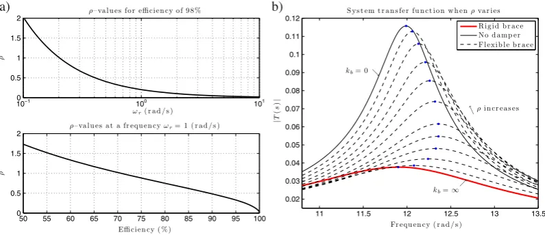
Figure 3. (a) Trend ofas target frequency!tand efficiencyEvaries; (b) frequency response of an SDOF system for different values offrom0to1.
D 1
!t
s
1
E.!t/2
1: (7)
Based on the monotonicity ofH.s/with respect to!, it can also be stated that
E.!/ >E.!t/I 8! < !t: (8)
Figure 3(a) shows the evolution of the parameterin Equation (7) as a function of either the target frequency for a desired efficiency of 98% or the efficiency for a target frequency of 1 (rad/s). Figure 3(b) shows the frequency response of an SDOF structure with an added brace–damper assembly from the transfer function in Equation (4). In the plot: D3%,!nD12(rad/s) andˇD1:5. Note that by varyingfrom0to1, that is, from the case of infinitely rigid brace to the case of no brace–damper assembly, not only the peak amplitude but also the resulting system frequency changes. Interestingly, increasing the brace stiffness initially results in an increase in the system’s frequency but only up to a certain level after which the frequency reduces to the damped frequency of the system if a pure dashpot (with an infinitely stiff brace) is considered.
2.3. Design criterion for the brace stiffness
The proposed method assumes that the damper size has already been determined in the usual way, that is, using an optimisation scheme in which the presence of the brace and its effects on the damper’s behaviour were neglected. Consider the case of an SDOF system with an added linear viscous damper. To design the brace stiffness that closely matches the behaviour of a pure dashpot, it is enough to use the undamped structural frequency as the target frequency in Equation (7) and select a high desired efficiency. We found that E.!n/ D 98% delivers a good trade-off in terms of brace size and final brace–damper assembly performance. Hence, by substituting these values into (7) and solving forkb, we can write an expression for the required brace stiffness as
kb Dcd!n
1
E.!n/2 1
12
: (9)
[image:6.595.100.498.68.240.2]this statement is valid for all the frequency bandwidth below the undamped natural frequency of the SDOF structure. A numerical example illustrating the use of this method along with an assessment of its accuracy is presented in Section 4.1
3. BRACED MULTI-DEGREE-OF-FREEDOM SYSTEMS
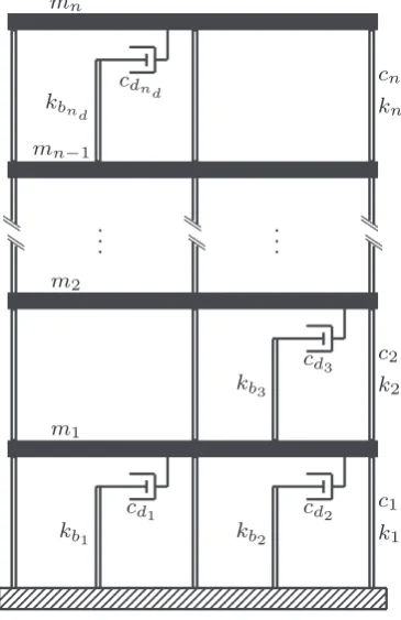
The previous analysis is now extended to multi-degree-of-freedom systems. Without loss of generality, we consider an n-storey building with nd supplemental brace–damper assemblies installed into the structure as shown in Figure 4. As before, we take into account the braces’ flexibility and formulate their interaction with the dampers through the Maxwell model. Hence, we can write an expression equivalent to Equation (1) at every level and collect them in matrix form. The system dynamics can then be described by means of the set of matrix equations (10).
MxR.t /CCxP.t /CKx.t /Cƒfd.t /D MexRg.t /
fd.t /CPfd.t /D…ƒTxP.t /
(10)
whereM,CandKare thennstructural mass, damping and stiffness matrices;xis then1 vector of structural displacements relative to ground;eis an1 unity vector;fdis thend1 vector of damper forces; is a diagonalnd ndmatrix with thei-th diagonal elementi Dcdi=kbi;…is a diagonal
ndnd matrix with thei-th diagonal elementcdi andƒis thennd location matrix for the brace–
[image:7.595.205.388.414.696.2]damper systems with respect to the masses. As an example of the location matrix, for a 3DOF structure with one brace–damper assembly located between the first and second masses,ƒDŒ1; 1; 0T. All the other parameters are as defined before in Section 2.
We first apply a modal transformation using the mode shape matrixˆto write
R
z.t /C2„Pz.t /C2z.t /C1ˆTƒfd.t /D 1ˆTMexRg.t /
fd.t /CPfd.t /D…ƒTˆPz.t /
(11)
where
x.t /Dˆz.t /I „DD.i/I DD.!i/I DˆTMˆDI (12)
in which the notationD.di/represents a diagonal matrix with thei-th diagonal element having the value di. Note that Cis assumed to be a classical damping matrix (Rayleigh damping), such that
ˆTCˆDD.2i!ii/wherei,!i andi are the modal damping, frequencies and masses, respec-tively. In addition, the matrix of mode shapes is normalised with respect to the structural mass as shown in [23].
Proceeding as before, we apply the Laplace transformation to the equations in (11) and then calculate the system transfer function.
Is2C2„sC2Z.s/CˆTƒFd.s/D ˆTMeAg.s/
ŒICsFd.s/D…ƒTˆsZ.s/
(13)
The transfer function matrix for the modal displacementsZ.s/with respect to the ground acceleration
Ag.s/is then calculated as
T.s/D hIs2C2„CˆTƒH.s/ƒTˆsC2i
1
ˆTMe (14)
where
H.s/DŒICs1…DD
c
di
1Cis
(15)
Equation (14) represents the dynamics in the frequency domain of a general MDOF system such as the one shown in Figure 4. Using an analogous approach to that for the case of SDOF systems, all the brace–damper assembly properties are fully encapsulated in the matrixH.s/. Note that (15) is a diagonal matrix and that these diagonal terms are first-order filter-like functions that model the effects of the brace compliance on the system dynamics. This matrix is diagonal because the brace acts only locally in reducing the efficacy of the damper that the brace is connected to. In addition, the contribution of every brace–damper assembly to each mode of vibration is accounted for as a consequence of the multiplication ofH.s/by the matrix of modal shapesˆ, the location matrixƒand their transposes as shown in Equation (14).
Extending the analytical approach we applied to the SDOF structure, if thei-th brace is infinitely rigid, then the corresponding parameter i in (15) becomes zero. Then the contribution of the i-th damper is 100% efficient with the structure observing the full damping cdi, the effects of which are
distributed across the structure according to the modal participation factors computed through the multiplications in Equation (14) as described before.
3.1. Determining the target frequency in MDOF structures
−100 −80 −60 −40
0 2 4 6 8 10 120
0.2 0.4 0.6 a)
−100 −80 −60 −40
0 2 4 6 8 10 120
[image:9.595.94.501.67.210.2]0.2 0.4 0.6 b)
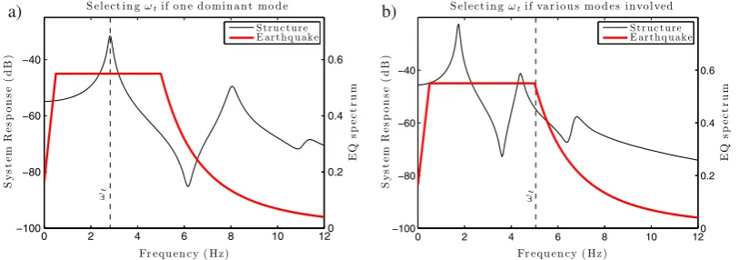
Figure 5. Selecting the target frequency !t in a 3DOF system. (a) As the first natural frequency of the structure if the first mode is dominant, (b) as the frequency at the edge of the design spectrum if several
modes are compromised.
i-th brace–damper assembly in the structure, it is more convenient to consider one universal value for the entire system. This is because of the frequency-dependent feature exhibited by the assembly’s efficiencyE as per its definition in Equation (6). Consequently, such a universal parametercan be selected in accordance with the level of efficiency desired within a specific frequency bandwidth.
Hence, in order to determine the suitable valuefor the MDOF structure, the target frequency!t has to be selected appropriately. We recall that this frequency corresponds to the right-hand end of the plateau in Figure 2 and represents the upper boundary of the frequency bandwidth where the assembly behaves with maximum efficiency. The higher the target frequency, the further the plateau will be extended, and the larger the brace that will be required. Therefore, the most favourable solution is the one given by selecting the minimum plausible target frequency. As an example, Figure 5 shows two limit scenarios for the case of a 3DOF structure to illustrate how the target frequency can be selected. The plots present the frequency response of the structure and the idealised expected ground motion spectrum (or the design spectrum conventionally considered for structural design purposes).
The plot on the left-hand side represents the scenario when the structural response is mainly driven by only one mode. In this case, the target frequency can be chosen as the frequency of that dominant mode. The plot on the right represents the scenario when several modes are prone to be excited by the expected ground motion. In such case, arguably the best choice is to select!t to be the frequency at the right corner of the idealised ground motion spectrum to ensure a close to optimal behaviour (Figure 5(b)).
3.2. Determining the brace sizes in MDOF structures
Once the target frequency has been defined, suitable stiffness for all braces can be determined from a simple expression. As mentioned earlier, this method assumes that the damper sizes have been determined beforehand with braces idealised as infinitely stiff elements.
For an MDOF structure with added linear viscous dampers, the stiffness required for thei-th brace such that the corresponding brace–damper assembly behaves nearly like a pure dashpot can be calcu-lated by means of Equation (16). Note that along with the target frequency determined as explained previously, one could use the brace–damper assemblies’ efficiencyEi to be as high as 98% as this offers
a good trade-off in terms of brace size and resulting brace–damper assembly performance. Neverthe-less, designers could select a different efficiency target for each brace–damper assembly independently based on their own design criteria. Similarly, the target frequency has to be introduced in rad/s, and the stiffness will be consistent with the units of the damping coefficientscdi, such that
kbi Dcdi!t
1
Ei.!t/
2 1
1
2
This equation can be applied to each assembly in the structure in an independent manner to ensure a structural performance comparable with the case when the braces were assumed to be rigid for all the frequency bandwidth below!t. In the next section, two numerical examples are discussed to illustrate the use of the proposed procedure.
4. NUMERICAL EXAMPLES
4.1. Example 1: Required brace stiffness for an SDOF.
To illustrate the use of the design procedure proposed in Section 2, consider an SDOF structure with floor mass of1000Kg, lateral stiffness of150kN/m and damping equal to3% of critical damping. Suppose that a linear damper with coefficientcd D4:2kNs/m has been selected to increase the overall structural damping up to20%.
We can apply Equation (9) to calculate the stiffness required by the brace to provide a brace–damper assembly that behaves close to the infinite brace stiffness case. After substituting the numerical values, we can calculate
kbD4:212:25
1
0:982 1
12
D253:32kN=m:
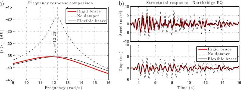
Notice that, here, forE.!n/D0:98, the brace stiffness is high compared to the structural stiffness; however, it will be seen that it is lower than that generated by three of the four other methods consid-ered. The dynamic response of the SDOF structure fitted with the brace–damper arrangement is first evaluated in terms of the frequency responseT .s/defined in Equation (4). Figure 6(a) presents three different conditions that are considered: the structure without any additional damping device (dashed line), the structure with the added damper and infinite brace stiffness (thick red line), and the structure with the damper and its supporting brace designed using the method proposed here (thin line). The plot shows that the response of the SDOF with the flexible brace is comparable to that of the idealised model with the infinitely rigid brace.
As discussed when presenting the method, the presence of a non-infinite brace stiffness results in deleterious performance only at frequencies higher than the target frequency, which in this case is!n. Nonetheless, this does not affect the overall structural response of the SDOF structure in a substantial manner. Figure 6(b) shows the dynamic response of the SDOF structure when subjected to an earth-quake. Again, the three aforementioned conditions are presented. Note that when the brace stiffnesskb designed by the proposed procedure is used, the system is able to track the response of the ideal case with negligible errors.
9 10 11 12 13 14 15 16 −45
−40 −35 −30 −25 −20 −15 a)
−10 −5 0 5 10
4 6 8 10 12 14 16
[image:10.595.101.497.536.684.2]−5 0 5 10 b)
Table I. Brace stiffness for the SDOF structure obtained from the different approaches.
kb
Approach (kN/m)
This paper 253:3
Fu and Kasai [20] 1500:0
Valles,et al.[21] (0:03k) 592:5
Valles,et al.[21] (0:10k) 191:5
Londoño,et al.[24] 280:6
9 10 11 12 13 14 15 −41
[image:11.595.209.386.205.363.2]−40 −39 −38 −37 −36 −35
Figure 7. Frequency responses of the SDOF structure with different values ofkb.
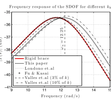
For comparison, we have calculated the brace stiffness required by considering the criteria suggested by three relevant previous works in [20, 21] and [24]. The first reference recommendskbto be10times the storey stiffness. The second one considers the transformation from the Kelvin model (linear spring and dashpot in parallel) to the Maxwell model. Note that this equivalence is only strictly valid at the frequency used in the transformation. Moreover, it is necessary to include a small fictitious stiffness in parallel with the damper in order to define a corresponding Maxwell model. Furthermore, the model outcome is extremely sensitive to the value of the fictitious stiffness chosen for the Maxwell model. We used the natural frequency of the system and arbitrarily selected two fictitious stiffness of3% and10% of the structural stiffness kto compute the results reported in what follows. The third reference is a recent work that presents a simple noniterative design procedure for brace–damper assemblies. We use the Optimum Brace Stiffness criterion proposed therein to calculate the brace stiffness given in Table I. Figure 7 presents a comparison among the frequency responses of the SDOF system with the added brace–damper assembly when the different brace stiffness are considered. Notice that although the
kb recommended by [20] results in a near-rigid behaviour, thekb value is six times greater than that calculated using the method proposed here. As this additional stiffness results in minimal benefit, this near-rigid brace arguably does not represent a cost-effective solution. Furthermore, unlike the procedure proposed in this paper, the transformation presented in [21] offers no indication of how the fictitious stiffness must be selected and how this relates to the final system behaviour, allowing for a very large set of broadly different solutions. Besides, the result offered by the proposed method is highly consistent with that one resulting from the simplified design rule presented in [24].
4.2. Example 2: Required stiffness for braces in a 10-storey structure.
KD
2 6 6 6 6 6 6 6 4
177:12 161:21 56:90 12:22 2:57 0:53 0:11 0:02 0:00 0:01
161:21 242:42 164:54 54:65 11:51 2:35 0:48 0:10 0:02 0:01 56:90 164:54 225:94 150:35 48:58 9:93 2:05 0:41 0:08 0:00
12:22 54:65 150:35 207:86 137:96 43:70 9:01 1:82 0:36 0:07 2:57 11:51 48:58 137:96 191:79 126:23 39:81 8:02 1:55 0:22
0:53 2:35 9:93 43:70 126:23 178:22 117:84 36:04 6:93 1:05 0:11 0:48 2:05 9:01 39:81 117:84 169:46 111:88 32:55 4:74
0:02 0:10 0:41 1:82 8:02 36:04 111:88 157:33 96:75 21:76 0:00 0:02 0:08 0:36 1:55 6:93 32:55 96:75 121:54 51:66 0:01 0:01 0:00 0:07 0:22 1:05 4:74 21:76 51:66 33:70
3 7 7 7 7 7 7 7 5
103kN
m
(17)
In addition, the mass of each storey is 50 tons, and an inherent 2% Rayleigh damping in the first and second modes is used. The cited references identified an optimal solution that comprises five damper locations at the first, third, fourth, fifth and sixth storeys with corresponding added damper coefficients:
cdi DŒ15305; 4182; 520; 1433; 3429kNs/m. The flexibility of the dampers’ supporting braces were
not considered when obtaining these optimal values.
The performance of the braces is evaluated by simulating the dynamic response of the 10-storey structure with added brace–damper systems under seismic base motion. The structure is excited by the records NGA–1048 and NGA–173 of the Pacific Earthquake Engineering Research Center ground motion database downloaded from [26]. These records are the unscaled fault-parallel component of the Northridge Earthquake in 1994 and the unscaled fault-parallel component of Imperial Valley Earthquake in 1979, respectively (Figure 8).
As pointed out in Section 3.1, the key factor when determining the brace stiffness for an MDOF structure is to identify the target frequency!t. To emphasise this aspect, we consider two cases: (i) selecting the first natural frequency of the structure without dampers as the target frequency (0.4 Hz for this structure) and (ii) selecting!tD3:5Hz. The second boundary was selected in such a way that the strongest segment of the frequency content of the earthquakes is covered (dashed lines in Figure 8). After selecting the target frequency, Equation (16) can be used straightforwardly. Table II presents the resulting brace stiffness calculated for each storey level.
It is worth noticing that one may want to distribute the additional damping in thei-th storey intoq
[image:12.595.98.499.67.151.2]damping devices each one with damping coefficient equal to.cdi=q/. In such case, the required brace
Figure 8. Seismic acceleration records: (a) Northridge Earthquake (Mag. 6:69). (b) Imperial Valley Earthquake (Mag.6:53).
Table II. Storey brace stiffnesskbi as a result of applying Equation (16) for every valuecdi.
Brace stiffness (103kN/m)
!t kb1 kb3 kb4 kb5 kb6
!n1 189:39 51:75 6:43 17:73 42:43
[image:12.595.107.491.426.574.2]Table III. Natural frequencies and damping ratios of the first five modes.
Natural frequencies (Hz) Damping ratio (%)
!t !1 !2 !3 !4 !5 1 2 3 4 5
None 0:40 1:32 2:43 3:80 5:55 2:0 2:0 3:1 4:6 6:6
!n1 0:51 1:72 3:29 4:64 7:04 23:8 10:2 11:0 8:0 9:5
3:5Hz 0:50 1:76 4:22 4:48 8:03 26:5 15:9 31:2 20:9 15:0
1 0:50 1:76 4:23 4:43 8:23 26:7 16:6 50:6 16:4 15:6
0 1 2 3 4 5 6
−70 −60 −50 −40 −30 −20 −10 0 10 20 a)
0 1 2 3 4 5 6
[image:13.595.104.492.175.345.2]−70 −60 −50 −40 −30 −20 −10 0 10 20 b)
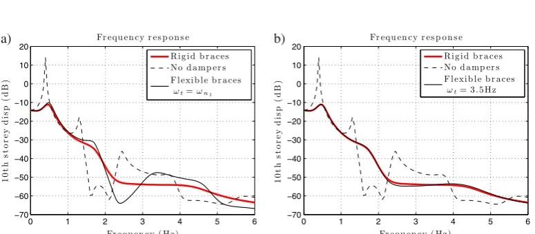
Figure 9. Comparison of the frequency responses at the top storey of the10-DOF structure. (a) Flexible braces calculated by selecting a target frequency of 0:4Hz. (b) Flexible braces calculated by selecting a
target frequency of3:5Hz.
stiffness would be the valuekbi reported in the previous table divided byq. Without loss of generality,
we assume that the additional damping will be condensed into one device at each corresponding storey – this will not affect the results presented hereafter.
Table III presents the resulting frequencies and damping ratios of the first five modes of vibration when considering the different scenarios. The row starting with ‘None’ refers to the case of the structure with no additional damping, while the row for !t D 1 refers to the ideal case of disregarding the presence of the supporting braces. By examining these values, it is clear that the case considering the target frequency equal to3:5Hz gives satisfactory agreement with the ideal case of pure dashpots with regard to both frequencies and damping ratios.
In addition, the frequency response of the structure in terms of the relative structural displacement at the top storey is presented in Figure 9. The response of two limit cases, the structure without dampers and the idealised structure with only dampers (infinitely rigid braces) are compared against the realistic case of including flexible supporting braces. Both plots show that for all frequencies lower than the target frequency, the structure with flexible braces closely follows the behaviour of the structure with only dampers. In view of the frequency content of the earthquakes under consideration, it is evident that the case in Figure 9(a) will yield poorer results.
To further assess the behaviour of the brace–damper assemblies with braces sized in line with the proposed procedure, we use the set of performance indices presented in Table IV [27]. The indicesJ1 andJ2 measure the improvements in terms of the acceleration response of the structure with added dampers compared to the system without dampers. The indicesJ3andJ4concern the peak displace-ment of the top floor and the overall inter-storey drift. Finally, the indexJ5considers the maximum damper force all over the building.
Table IV. Definition of the performance indices [27].
Index Description
J1Dmax
8t;i j Rx
i.t /jc
j Rxmax i ju
Normalised peak floor acceleration. L1-norm.
J2Dmax
8t;i k Rx
i.t /kc
k Rxmax i ku
Normalised peak floor acceleration. L2-norm.
J3Dmax
8t jx
top.t /jc
jxmax topju
Normalised peak top floor displacement.
J4Dmax
8t;i
jdi.t /jc
jdmax i ju
Normalised overall inter-storey drift.
J5Dmax
8t;i jf
di.t /j 100kN
Normalised maximum damper force.
[image:14.595.106.495.234.370.2]c: structure with added brace–dampers; u: uncontrolled structure
Figure 10. Top floor response of the 10-DOF structure with brace–damper systems subject to the Northridge earthquake. (a) Target frequency equal to0:4Hz, (b) Target frequency equal to3:5Hz.
Figure 11. Top floor response of the 10-DOF structure with brace–damper systems subject to the Imperial Valley earthquake. (a) Target frequency equal to0:4Hz, (b) Target frequency equal to3:5Hz.
Table V. Performance index assessment.
!t Northridge Imperial Valley
J1 J2 J3 J4 J5 J1 J2 J3 J4 J5
!n1 1:54 2:37 0:28 0:65 6:43 1:15 1:31 0:60 0:97 9:37
3:5Hz 1:36 1:85 0:25 0:53 5:86 1:08 1:18 0:55 0:86 9:99
[image:14.595.103.495.426.565.2] [image:14.595.141.459.634.707.2]provided with braces of infinite stiffness is compared against the case of flexible braces for the two different values of the target frequency.
From the plots, it can be seen that the brace–damper assemblies whose braces were sized in accor-dance with the method in Section 3.1 behave satisfactorily and are comparable to the ideal case of rigid braces. A detailed quantitative evaluation was carried out by using the performance indices defined previously. The results are presented in Table V for the two earthquakes.
The performance indices of the structure with flexible braces sized by using!t D 3:5Hz show excellent agreement with the performance indices of the ideal case. This confirms that the proposed procedure can deliver fast solutions close to optimality.
5. CONCLUDING REMARKS
A study of the influence of brace stiffness on the damping action of linear viscous fluid dampers has been presented. Based on the observation that the effects of brace stiffness can be represented as a first-order filter, a new approach has been proposed. Firstly, the dampers are sized in the normal way, using an optimisation strategy that assumes the braces are infinitely stiff elements. Then the minimum brace stiffnesses are calculated based on desired damper efficiency over a predetermined frequency range.
Based on the study of a single-degree-of-freedom structure, we demonstrated that the resulting brace–damper assembly behaves nearly as a pure dashpot within a selected frequency bandwidth by preserving a desired level of the damper’s efficiency. The analysis was extended to the case of multi-degree-of-freedom systems to show that the design criteria can be applied straightforwardly. Numerical simulations of systems with added brace–damper assemblies acting under earthquake excitation were used to show the optimality of the solutions delivered using the proposed design procedure. Several performance indices were used to quantify the dynamic behaviour and compare different scenarios showing that the desired performance was achieved.
Because the optimal damper sizes are required to be known a priori for the ideal case of infinitely rigid braces, the method presented here can be seen as an additional tool, which is complementary to conventional damper design strategies. The main limitation of this method is that this applies only to structures that fit the definitions given in Equation (10).
ACKNOWLEDGEMENTS
Dr Londono was supported by the Royal Academy of Engineering through a Newton International Fellowship –Round 2010(http://www.newtonfellowships.org/). Prof. Wagg is supported by the EPSRC grant EP/K003836/1, and Prof. Neild is supported by the EPSRC Fellowship EP/K005375/1. These financial supports are gratefully acknowledged.
REFERENCES
1. Soong T, Dargush G. Passive Energy Dissipation Systems in Structural Engineering, John Wiley & Sons Ltd: Chichester, UK, 1997.
2. Hanson RD, Soong TT.Seismic Design with Supplemental Energy Dissipation Devices. MNO–8, EERI Monograph, 2001.
3. Foti D, Diaferio M, Nobile R. Dynamic behavior of new aluminum–steel energy dissipating devices.Structural Control and Health Monitoring2013;20(7):1106–1119. DOI:10.1002/stc.1557.
4. ¸Sigaher AN, Constantinou MC. Scissor–jack–damper energy dissipation system. Earthquake Spectra 2003;
19(1):133–158. DOI:10.1193/1.1540999.
5. Constantinou MC, Tsopelas P, Hammel W, Sigaher AN. Toggle-brace-damper seismic energy dissipation systems. Journal of Structural Engineering, ASCE2001;127(2):105–112.
6. Gluck J, Ribakov Y. Active viscous damping system with amplifying braces for control of MDOF structures. Earthquake Engineering & Structural Dynamics2002;31(9):1735–1751. DOI:10.1002/eqe.202.
7. Lavan O, Levy R. Optimal design of supplemental viscous dampers for irregular shear-frames in the presence of yielding.Earthquake Engineering & Structural Dynamics2005;34(8):889–907. DOI:10.1002/eqe.458.
9. Yang JN, Lin S, Kim JH, Agrawal AK. Optimal design of passive energy dissipation systems based onh1a and
h2performances.Earthquake Engineering and Structural Dynamics2002;31(4):921–936. DOI:10.1002/eqe.130.
10. Singh MP, Moreschi LM. Optimal seismic response control with dampers.Earthquake Engineering & Structural Dynamics2001;30(4):553–572. DOI:10.1002/eqe.23.
11. Londoño JM, Neild S, Wagg D. Estimating the overall damping ratio in structures with brace–damper systems, Proceedings of the 15th World Conference on Earthquake Engineering. 15WCEE: Paper 0508, Lisbon, Portugal, 2012.
12. Agranovich G, Ribakov Y. A method for efficient placement of active dampers in seismically excited structures. Structural Control and Health Monitoring2010;17(5):513–531. DOI:10.1002/stc.329.
13. Lavan O, Levy R. Optimal design of supplemental viscous dampers for linear framed structures. Earthquake Engineering & Structural Dynamics2006;35(3):337–356. DOI:10.1002/eqe.524.
14. Bishop J, Striz A. On using genetic algorithms for optimum damper placement in space trusses.Structural and Multidisciplinary Optimization2004;28:136–145. DOI:10.1007/s00158-004-0441-9.
15. Wu B, Ou JP. Optimal placement of energy dissipation devices for three dimensional structures. Engineering Structures1997;19(2):113–125.
16. Takewaki I, Yoshitomi S. Effects of support stiffnesses on optimal damper placement for a planar building frame. The Structural Design of Tall Buildings1998;7(4):323–336. DOI:10.1002/(SICI)1099-1794(199812)7:4<323::AID-TAL115>3.0.CO;2-L.
17. Park JH, Kim J, Min KW. Optimal design of added viscoelastic dampers and supporting braces. Earthquake Engineering & Structural Dynamics2004;33(4):465–484. DOI:10.1002/eqe.359.
18. Singh M, Verma N, Moreschi L. Seismic analysis and design with maxwell dampers.Journal of Engineering Mechanics2003;129(3):273–282. DOI:10.1061/(ASCE)0733-9399(2003)129:3(273).
19. Chen YT, Chai YH. Effects of brace stiffness on performance of structures with supplemental maxwell model-based brace–damper systems.Earthquake Engineering & Structural Dynamics2011;40(1):75–92. DOI:10.1002/eqe.1023. 20. Fu Y, Kasai K. Comparative study of frames using viscoelastic and viscous dampers. Journal of Structural
Engineering, ASCE1998;124(5):513–522. DOI:10.1061/(ASCE)0733-9445(1998)124:5(513).
21. Valles R, Reinhorn A, Kunnath S, Li C, Madan A. IDARC2D, version 4.0: A computer program for the inelas-tic damage analysis of buildings.Technical Report NCEER-96-0010, National Center for Earthquake Engineering Research: SUNY, Buffalo, 1996.
22. Meyers MA, Chawla KK.Mechanical Behavior of Materials, (2nd edn), Cambridge University Press: Cambridge, UK, 2009.
23. Clough RW, Penzien J. Dynamics of Structures, McGraw–Hill international editions, Civil engineering series, McGraw-Hill Book Co.: Singapore, 1993.
24. Londoño JM, Neild S, Wagg D. A noniterative design procedure for supplemental brace–damper systems in single-degree-of-freedom systems. Earthquake Engineering & Structural Dynamics 2013; 42(15):2361–2367. DOI:10.1002/eqe.2339.
25. Levy R, Lavan O. Quantitative comparison of optimization approaches for the design of supplemen-tal damping in earthquake engineering practice. Journal of Structural Engineering 2009; 135(3):321–325. DOI:10.1061/(ASCE)0733-9445(2009)135:3(321).
26. Pacific Earthquake Engineering Research Center.Ground Motion Database, University of California: Berkeley, July 2012. Available from: http://peer.berkeley.edu/peer_ground_motion_database [Accessed on 12 July 2012]. 27. Spencer BF, Dyke SJ, Deoskar HS. Benchmark problems in structural control: Part I–active mass driver

![Table IV. Definition of the performance indices [27].](https://thumb-us.123doks.com/thumbv2/123dok_us/7945971.196452/14.595.141.459.634.707/table-iv-denition-of-the-performance-indices.webp)
