Optically controlled dense current structures driven by relativistic
plasma aperture-induced di
ff
raction
B. Gonzalez-Izquierdo,1 R. J. Gray,1 M. King,1 R. J. Dance,1 R. Wilson,1 J. McCreadie,1 N. M. H. Butler,1 R. Capdessus,1 S. Hawkes,2 J. S. Green,2 M. Borghesi,3 D. Neely,2, 1 and P. McKenna1,∗ 1SUPA Department of Physics, University of Strathclyde, Glasgow G4 0NG, UK 2Central Laser Facility, STFC Rutherford Appleton Laboratory, Oxfordshire OX11 0QX, UK
3Centre for Plasma Physics, Queens University Belfast, Belfast BT7 1NN, UK
Abstract
The collective response of charged particles to intense fields is intrinsic to plasma accelerators
and radiation sources, relativistic optics and many astrophysical phenomena. Here we show that
the fundamental optical process of diffraction occurs via the generation of a relativistic plasma
aperture in thin foils undergoing relativistic induced transparency. The plasma electrons
col-lectively respond to the resulting near-field diffraction pattern, producing a beam of energetic
electrons with spatial structure which can be controlled by variation of the laser polarization,
wavelength and focused intensity profile. The concept is demonstrated numerically and verified
experimentally. The results provide new understanding of the formation of current structures in
the relativistically transparent regime of laser-plasma interactions and is a viable step towards
optical control of charged particle dynamics in laser-driven sources.
∗
The formation of current structures due to the collective response of charged par-ticles to a perturbation is one of the most fundamental properties of plasma. This is manifest in plasma dynamics ranging from flares and X-ray jets on the sun to disrup-tive instabilities in fusion plasmas. This feature is also exploited to great effect in the development of compact laser-based particle accelerators and radiation sources, which have wide-ranging potential applications in science, medicine and industry. Controlling the collective motion of plasma electrons in response to perturbation produced by in-tense laser light is key to the development of these novel sources. Pertinent examples in plasma with density low enough for laser light to propagate (underdense plasma) include the self-generated plasma cavity or ‘bubble’ produced in laser-driven wakefield acceler-ation [1] and plasma channels [2]. These structures are formed principally by the pon-deromotive force induced by the propagating laser pulse, which expels electrons from the regions of high laser intensity, and by self-generated fields induced by the current displacement [3]. Shaping the spatial-intensity profile of a laser focus enables control over the collective electron motion and thereby the properties of the beams of high en-ergy particles and radiation produced. In the case of wakefield acceleration, for example, the laser focal spot size is matched to the size of the plasma bubble as defined by the characteristic plasma oscillation frequency in order to optimize the acceleration [4]. For ultrashort pulses the degree of control on the intensity profile is typically limited to vari-ation of the laser focal spot size by changing the F-number of the focusing optic or by using a deformable mirror to control the laser wavefront.
fun-damental optical process of diffraction produced by a self-generated circular ‘relativistic plasma aperture’ and that the resulting near-field diffraction pattern defines the collec-tive plasma dynamics. It is shown, via particle-in-cell (PIC) simulations and experiment, that this determines the spatial-intensity distribution of the beam of relativistic electrons accelerated, thus providing fundamental new understanding of current structure forma-tion in the relativistic induced transparency (RIT) regime of laser-plasma interacforma-tions. We demonstrate control of the electron distribution by variation of the laser polarization to induce dynamic diffraction patterns.
NEAR-FIELD DIFFRACTION DURING RELATIVISTIC INDUCED TRANSPARENCY
The interference of waves which encounter a pinhole (or other obstacle) that is com-parable in size to the wavelength gives rise to diffraction phenomenon according to the Huygens-Fresnel principle [28, 29]. In the case of a thin foil target undergoing RIT, a region of the target near the peak of the focused intensity becomes relativistically under-dense to the laser light. In this regionne< n0c, whereneis the plasma electron density and
n0c=γme0ω2L/e2 is the relativistically corrected critical plasma density (γ is the Lorentz factor,me is the electron rest mass,0 is the vacuum permittivity,ωLis the angular laser frequency and e is the electron charge). The diameter of this circular region, shown schematically in Fig. 1a for a Gaussian laser pulse, depends on the intensity profile of the focal spot and the plasma expansion characteristics. It will typically be of the order of the full width at half maximum (FWHM) of the laser focus and therefore ∼2-3 times
the laser wavelength for a tightly focused (near diffraction limited) beam. Thus, after formation of this aperture on the pulse rising edge, the conditions are ideal for strong diffraction of the remainder of the laser pulse propagating through it.
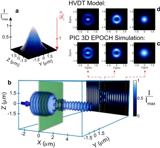
1.2 µm. The pattern diffracts into an even-IG00 mode in the far-field. The distribution is fully described by a vectorial analysis using Hertz Vector Diffraction Theory (HVDT) [30], as shown in Fig. 1d.
Next we replace the fixed aperture target with a uniform thin foil (i.e. initially with-out aperture) and investigate the laser-generated ‘relativistic plasma aperture’, the effect this has on the propagating laser light and in turn how the evolving laser spatial profile influences the beam of fast electrons accelerated forward. This is investigated using full 3D PIC simulations for the same laser pulse and target parameters as the experiment discussed below.
Figure 2a-d shows an example simulation result for the laser intensity and electron density just after RIT occurs. The laser light is linearly-polarized, along the Y-axis. Inter-ference between laser light which is reflected from the target before RIT occurs and the remaining incoming laser light results in a standing wave distribution with local nodes and anti-nodes at the target front side (X<0). Despite local deformation of the target due to laser radiation pressure, during RIT the remainder of the laser pulse diffracts as it passes through the evolving plasma aperture. The resulting diffraction pattern at the target rear is very similar, in both the near and far fields, to that shown in Fig. 1. Furthermore, the simulation clearly shows that the accelerated electrons respond to the diffracted laser intensity distribution. In Fig. 2c, at the X position at which the electron density is highest on axis (X∼1µm), the laser profile has a double diffraction lobe
POLARIZATION SENSITIVITY
Given that diffraction in the near-field is sensitive to laser polarization, we next con-sider the extent to which the electron beam spatial distribution can be controlled by changing the polarization. The results in Fig. 2a-d are for linearly polarized pulses. Cor-responding simulation results are presented for elliptical and circular polarization in Fig. 2e-g and Fig. 2h-j, respectively. The results are explained with reference to model cal-culations of the angular velocity of the polarization vector and magnitude of the electric field as shown in Fig. 2k-m for one laser period. In the linear polarization case the laser electric field flips between the two lobes over each half-laser period, producing the an-gular asymmetry in the ponderomotive force discussed above. With circularly polarized light, because the phase difference is π/2, the field components produce a dynamic in-tensity profile which makes a complete rotation at constant angular velocity around the laser propagation axis once per laser period. The instantaneous radial ponderomotive force is asymmetric, as shown in Fig. 2j, but when averaged over a laser period (or more) a ring-like electron distribution centred on the laser propagation axis is produced. The elliptical polarization (π/4 ellipticity) case exhibits elements of both types of behaviour. The polarization vector rotates, but with an angular velocity which varies over the laser period. The magnitude of the laser electric field is highest during the part of the laser period where the polarization vector rotates slowest, as seen when comparing the red phases of the curves in Fig.2k-m. The plasma electrons respond to the angular variation in the radial ponderomotive force to produce a double lobe orientated perpendicular to the ‘average’ polarization axis (the red parts of the circle in Fig. 2g correspond to the red phases of the curves in Fig. 2k-m).
We note that the use of circularly polarized light results in significantly less electron heating and expansion and consequently more radiation-pressure-driven target defor-mation. RIT therefore occurs later in the interaction, producing a smaller aperture com-pared to the linear and elliptical cases.
The rotating laser diffraction structure instigates an in-phase rotation of a structure in the plasma electron density as shown in the time-resolved results in Fig. 3. The struc-ture continues to rotate after the laser pulse has decayed, at∼120 fs, resulting in a
radius of curvature about the propagation axis and a lower density of electrons which ‘escape’ from the rotating structure to larger radii, as shown in Fig. 3c.
The behaviour predicted in these simulations was tested experimentally using the Gemini laser [31], which delivers light with a central wavelength of 800 nm in pulses with 40 fs FWHM duration. The peak laser intensity for these measurements was 6×10²⁰
Wcm−2and the targets were 10 nm-thick Al. Figure4compares example time-integrated measurements of the electron beam measured in the Y-Z plane with the 3D EPOCH sim-ulation results integrated over 5 laser cycles at the end of the pulse, for all three po-larization cases. As the measurements are made 3 cm downstream from the target, the comparison is made in terms of electron angular deflection (as sampled at X=6µm in the simulations). From the discussion above, the circular polarized case may be expected to produce an electron density ring due to the constant rotational velocity and electric field as shown in Fig. 2k-m. However, the simulations show that in fact there is a slight distor-tion in the polarizadistor-tion induced by the evolving plasma aperture, resulting in a ring-like distribution with localized maxima.
The experiment results verify the behaviour observed in the simulations for all three polarization cases, as shown in Fig. 4. The measured double-lobe electron density fea-ture matches the simulation predictions in terms of the angular separation of the lobes and their orientation with respect to the polarization axes for both the linear and ellipti-cal cases. The larger measured angular width of the lobes may result from space-charge spreading of the beam as it propagates downstream towards the detector. The measure-ments for circularly-polarized light reproduce both the small-radius central ring with local maxima (labelled 1) and the lower density distributions at larger radii (labelled 2) in Fig. 4c for electrons with energy greater than 3.5 MeV. The corresponding circular density profile for electrons with energies above 17 MeV is also reproduced experimen-tally, as shown in Fig.4g.
direction. We have previously reported an experimental observation of a similar dou-ble lobe structure, but again only for linearly polarized light [33]. By investigating the sensitivity of the electron distribution to the drive laser polarization, numerically and ex-perimentally, the present study reveals that the underpinning physics giving rise to the lobe features arises from diffraction. This is further confirmed by simulations discussed below in which the relativistic plasma aperture diameter is varied.
ELECTRON SPATIAL PROFILE DEPENDENCE ON APERTURE SIZE
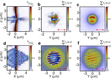
The relativistic plasma aperture diameter is defined by the condition ne< n0c and in-creases with peak laser intensity for a given target material and thickness. Figure 5a-c and d-f shows p-polarization simulation results with the laser focus diameter (FWHM) equal to 1.5 µm and 6 µm, respectively. These results are directly comparable to the 3
µm case in Fig. 2a-d (the peak laser intensity and duration and target parameters are the same). The smaller aperture case results in a single laser diffraction node, stretched in the polarization direction (Y-axis), which ponderomotively expels electrons preferentially in both directions in Z, producing a double lobe electron density distribution. Unlike the 3 µm case, because a single laser node is produced on-axis there isn’t a secondary low density axial electron population produced. With increasing aperture size the number of maxima in the near-field diffraction in the vicinity of the electrons increases. These take the form of intense laser ‘stripes’ orientated along the polarization direction, as shown in Fig. 5e. As clearly shown in Fig.5f, the electrons are deflected to form a similarly striped pattern, interleaved with the laser stripes. The periodicity of this grating-like structure is 1.2 µm. Evolving structures of this type may find application in driving secondary radiation sources.
RESULTANT MAGNETIC FIELD STRUCTURES AND ANALOGOUS SYSTEMS
electrons can be modified and that rotational, time-dependant structures can be induced. This opens up a new direction in spatial and temporal control of electron motion in dense plasma and by extension the evolution of the high fields used to accelerate charged par-ticles and to produce high energy radiation.
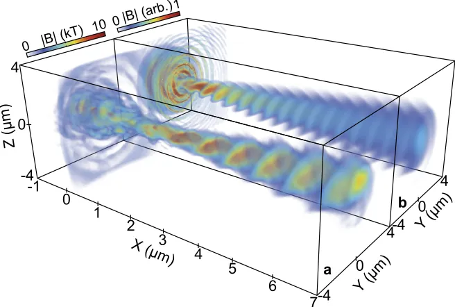
These dynamic diffraction effects can give rise to interesting and potentially useful magnetic field structures. By observing the resultant magnetic field from the circularly polarized laser-diffraction and collective plasma behaviour, it can be seen that the mag-nitude of the magnetic field becomes helical in structure, tightly precessing at a radius close to that of the plasma aperture (0.75 µm), as shown in Fig. 6a. When compared to the magnetic field generated by a lower intensity (but otherwise identical) circularly polarized laser, propagating through a comparable fixed circular aperture of 0.75 µm radius (i.e. no plasma; Fig. 6b), it is clear that the diffraction effects play a key role in the formation of such a magnetic field structure. This magnetic field is shown in both cases 30 fs after the peak laser intensity has propagated through the aperture. The laser pulse propagating through the fixed aperture produces a magnetic field which is strongest close to the aperture, reducing as the beam expands. By contrast, in the rela-tivistic plasma aperture case the magnetic field is strong over a longer range and is more helical, suggesting that the field is modified by the induced plasma current structure. The underlying physics of the collective plasma effects on the magnetic field will be the subject of future investigation.
The current and field structures produced in this way could be used to generate lab-oratory analogues of astrophysical phenomena. Similar magnetic field structures have been detected in jets originating from active galactic nuclei, such as 3C 273 [34]. Such structures are commonly identified as being generated from the rotation of the accretion disk, whilst the analogous structures seen here arise from the rotation of the diffraction pattern. Further similarities to these jets can be observed in that the highest momentum component of the accelerated electrons occur along the central laser axis. Surrounding this region, the electron momentum reduces, as seen in Fig. 6, resulting in an electron beam with properties similar to that of the spine-sheath jet morphology [35].
laser-plasma interaction that similar whistler modes are being generated.
The present work reveals a new phenomenon in relativistic plasma optics. It pro-vides new insight into fundamental aspects of laser-matter interactions in the relativistic intensity regime and identifies the emergence of optically controlled dynamic current structures in dense plasma. This stimulates the exploration of new avenues in laboratory astrophysics and in novel radiation and particle source development.
METHODS
Experiment
The experiment results were obtained using the Gemini [31] Ti:sapphire laser at Rutherford Appleton Laboratory in the UK. The central wavelength is optimized at 800 nm and the pulse duration was 40 fs (FWHM). The laser beam was focused along target normal onto the front surface of 10 nm-thick aluminium foils, using an off-axis
f/2 parabola, to a focal spot diameter of 3 µm (FWHM). The laser pulse energy was 2 J, giving a calculated peak intensity of 6×10²⁰ Wcm−2. A double plasma mirror
config-uration was used to enhance the intensity contrast to∼1011 and ∼108, at 1 ns and 5 ps,
respectively, prior to the peak of the pulse. A deformable mirror was used prior to the focusing parabola to ensure a high quality focal spot on target. Thin mica wave plates were used to switch between linear (∆θ= 0), elliptical (∆θ=π/4) and circular (∆θ=π/2) polarization, where ∆θ is the phase difference between the two orthogonal components of the laser beam. The 2D spatial-intensity distribution of the electron beam was mea-sured 3 cm downstream from the target using passive stacked layers of Fujifilm imaging plate, interleaved with iron filters to provide energy filtering. The filtering before the first layer is sufficient to prevent the detection of any protons or heavier ions produced.
Analytical modelling
The near-field diffraction pattern, in the region of maximum interaction between the laser and the plasma electrons, is of particular interest here. Although other analytical models like the scalar Rayleigh-Sommerfeld [37] or Fresnel-Kirchhoff[38] models can be used to study diffraction induced by an aperture, they work in the limit that the aperture radius is much bigger than the laser wavelength, that the electric field in the plane of the aperture is known and involve a scalar treatment of the diffracted light. We use the HVDT model to avoid these limitations.
The analytical results reported in Fig. 2k-m were obtained by solving the following equations which describe the two orthogonal electric field components for the different polarizations considered. The orthogonal electric field components areE~y=E0y·sin(φ)~y andE~z=E0z·sin(φ−∆θ)~z, where∆θis the phase difference. For linear polarization∆θ= 0 andE0z = 0; for elliptical polarization∆θ=π/4 andE0y=E0z; and for circular polariza-tion∆θ=π/2 andE0y =E0z. The angle with respect to the +Y axis isθE~yE~z =tan−1
~ Ez/E~y
and the rotational angular velocity with respect to the +Y axis isωR=dθEy ~~Ez/dt. The
mag-nitude of the total electric field iskET(E~y, ~Ez)k= q
~ Ey
2 +E~z
2 .
Simulations
The simulations were performed using the fully relativistic 3D EPOCH particle-in-cell (PIC) code [39]. The simulation space is defined as a 20 µm×20µm ×20µm box with
1000×720×720 computational mesh cells. The laser wavelength is 800 nm. The pulse
has a Gaussian temporal profile with 40 fs FWHM width, focused to a Gaussian intensity distribution of 3µm FWHM. The peak laser intensity is 6×10²⁰ Wcm−2. Simulations are
performed with the laser pulse polarized linearly (p-polarization), elliptically (ellipticity of π/4) or circularly. The simulations are run for a total duration of 200 fs to ensure full propagation of the laser pulse through the simulation space. The target is a fully ionized 10 nm-thick Al13+ slab with 6 nm-thick C6+and H+ mixed contamination layers (assumed to be a hydrocarbon with the form C2H6) on the front and rear surfaces. In order to resolve the physics within such an ultra-thin target, it is necessary to pre-expand the target and contamination layers with a 245 nm FWHM Gaussian profile, giving peak densities of ∼1.3nc Al13+, ∼1.3nc H+ and ∼0.4nc C6+, where nc is the critical plasma
electron temperature was set at 100 keV. Initially there were ∼22 simulation particles
per cell per species (total of 3.11×10⁹ simulation particles). The code assumed no binary
collisions.
REFERENCES
[1] Pukhov, A. & Meyer-ter-Vehn, J. Laser wake field acceleration: the highly non-linear
broken-wave regime.Appl. Phys. B74,355-361 (2002)
[2] Pukhov, A. & Meyer-ter-Vehn, J. Relativistic magnetic self-channeling of light in near-critical
plasma: three-dimensional particle-in-cell simulation.Phys. Rev. Lett.76,3975 (1996)
[3] Kaluza M.C.et al.Measurement of magnetic-field Structures in a laser-wakefield accelerator.
Phys. Rev. Lett.105,115002 (2010)
[4] Thomas A.G.R.et al.Effect of laser-focusing conditions on propagation and monoenergetic
electron production in laser-wakefield accelerators.Phys. Rev. Lett.98,095004 (2007)
[5] Daido H.et al.Review of laser-driven ion sources and their applications.Rep. Prog. Phys.75,
056401 (2012)
[6] Macchi A.et al. Ion acceleration by superintense laser-plasma interaction.Rev. Mod. Phys.
85,751 (2013)
[7] Ganeev R.A. High-order harmonic generation in a laser plasma: a review of recent
achieve-ments.J. Phys. B: At. Mol. Opt. Phys40,R213 (2007)
[8] Dromey B.et al.High harmonic generation in the relativistic limit.Nature Phys.2,456-459
(2006)
[9] Kaw P. and Dawson J. Relativistic nonlinear propagation of laser beams in cold overdense
plasmas.Phys. Fluids13,472 (1970)
[10] Guerin S. et al.Propagation of ultraintense laser pulses through overdense plasma layers.
Phys. Plasmas3,2693 (1996)
[11] Fuchs J. et al. Transmission through highly overdense plasma slabs with a subpicosecond
relativistic laser pulse.Phys. Rev. Lett.80,2326 (1998)
[12] Cattani F.et al.Threshold of induced transparency in the relativistic interaction of an
[13] Tushentsov M. et al.Electromagnetic energy penetration in the self-induced transparency
regime of relativistic laser-plasma interactions.Phys. Rev Lett.87,275002 (2001)
[14] Willingale L. et al. Characterization of high-intensity laser propagation in the relativistic
transparent regime through measurements of energetic proton beams.Phys. Rev. Lett.102,
125002 (2009)
[15] Eremin V.I.et al.Relativistic self-induced transparency effect during ultraintense laser
in-teraction with overdense plasmas: why it occurs and its use for ultrashort electron bunch
generation.Phys. Plasmas17,043102 (2010)
[16] Vshivkov V.A. et al. Nonlinear electrodynamics of the interaction of ultra-intense laser
pulses with a thin foil.Phys. Plasmas5,2727 (1998)
[17] Yu W.et al.Model for transmission of ultrastrong laser pulses through thin foil targets.Phys.
Rev. E59,3583 (1999)
[18] Reed S.A.et al.Relativistic plasma shutter for ultraintense laser pulses.Appl. Phys. Lett.94,
201117 (2009)
[19] Wang H.Y.et al.Laser shaping of relativistic intense, short Gaussian pulse by a plasma lens.
Phys. Rev. Lett.107,265002 (2011)
[20] Palaniyappan S. et al. Dynamics of relativistic transparency and optical shuttering in
ex-panding overdense plasmas.Nature Phys.8,11 (2012)
[21] Stark. D.J.et al.Relativistic plasma polarizer: impact of temperature anisotropy on
relativis-tic transparency.Phys. Rev. Lett.115,025002 (2015)
[22] Henig. A. et al. Enhanced laser-driven ion acceleration in the relativistic transparency
regime.Phys. Rev. Lett.103,045002 (2009)
[23] Macchi A.et al.“Light Sail” acceleration reexamined.Phys. Rev. Lett.103,085003 (2009)
[24] Dromey B.et al.Coherent synchrotron emission from electron nanobunches formed in
rela-tivistic laser-plasma interactions.Nature Phys.8,11 (2012)
[25] Dromey B.et al.Coherent synchrotron emission in transmission from ultrathin relativistic
laser pasmas.New J. Phys.15,015025 (2013)
[26] Kiefer D.et al.Relativistic electron mirrors from nanoscale foils for coherent frequency
up-shift to the extreme ultraviolet.Nat. Commun.4,1763 (2013)
[27] Yeung M. et al. Dependence of laser-driven coherent synchrotron emission efficiency on
[28] Fresnel A. Memoire sur la Diffraction de la LumiereAnn. Chim et Phys.1,129 (1816)
[29] Stratton, J.A. & Chu, L.J. Diffraction theory of electromagnetic waves.Phys. Rev.56,99–107
(1939)
[30] Guha, S. & Gillen, G. Description of light propagation through a circular aperture using
nonparaxial vector diffraction theory.Opt. Express13,1424-1447 (2005)
[31] Hooker C.J.et al.The Astra Gemini project - A dual-beam petawatt Ti:Sapphire laser system.
J. Phys. IV France133,673-677 (2006)
[32] Yin, L. et al. Three-Dimensional dynamics of breakout afterburner ion acceleration using
high-contrast short-pulse laser and nanoscale targets.Phys. Rev. Lett.107,045003 (2011)
[33] Gray, R.J.et al.Azimuthal asymmetry in collective electron dynamics in relativistically
trans-parent laser-foil interactions.New J. Phys.16,093027 (2014)
[34] Asada K. et al.A helical magnetic field in the jet of 3C 273.Publ. Astron. Soc. Japan54,(3)
L39-L43 (2002)
[35] Ghisellini G.et al.Structured jets in TeV BL Lac objects and radiogalaxies.Astron. Astrophy.
432,401-410 (2005)
[36] Urrutia J. M. and Stenzel R. L. Magnetic antenna excitation of whistler modes. I. basic
prop-erties.Phys. Plasmas21,122107 (2014)
[37] Rayleigh, J.W. On the passage of waves through apertures in Plane screens, and allied
prob-lems.Philos. Mag.43,259-272 (1897)
[38] Kirchhoff, G.R. Zur theorie der lichtstrahlen.Ann. Phys.254,663-695 (1883)
[39] Brady C.S. and Arber T.D. An ion acceleration mechanism in laser illuminated targets with
internal electron density structure.Plasma Phys. Control. Fusion53,015001 (2001)
ACKNOWLEDGMENTS
devel-oped under EPSRC grant EP/G054940/1.
AUTHOR CONTRIBUTIONS
B.G.-I., R.J.G., M.K. and P.M. conceived the experiment. R.J.G., R.J.D., B.G.-I., R.W., J.M., N.M.H.B., S.H., J.S.G. and P.M. executed the experiment and B.G.-I. and R.J.G. per-formed the analysis of the experimental data. M.K. and B.G.-I. perper-formed the simulations and analysis of the simulation results, with contributions from R.C.. P.M. provided over-all supervision of the work, with contributions from D.N. and M.B.. The manuscript was prepared by P.M., B.G.-I., M.K. and R.J.G. with contributions from all authors.
ADDITIONAL INFORMATION
Data associated with research published in this paper can be accessed by contacting the corresponding author.
COMPETING FINANCIAL INTERESTS
Y(µm)
Z(
µm)
-1.5 0 1.5 1.5
0
-1.5
Y(µm) -1.5 0 1.5 1.5 0 -1.5 1 0.5 0
I
I
max Z( µm) Z ( µ m)X (µm)
0 2 4 -2 -1.5 1.5 I Imax 0
-1.501.5
Y (µm)
ne
γnc
Y(µm) -1.5 0 1.5 1.5
0
-1.5
-1.5 0 1.5 1.5
0
-1.5 -1.5 0 1.5 1.5
0
-1.5 -1.5 0 1.5 1.5
0
-1.5
1
Y (µm)
Z (µ
m) 0.5 1.5 -1.5 0 1.5 -1.5 0 1 HVDT Model:
PIC 3D EPOCH Simulation:
a
b
d
[image:15.612.145.462.76.370.2]c
Figure 1: Intensity diffraction pattern induced by a fixed aperture. a, Schematic showing the Gaussian
spatial-intensity distribution of an ultraintense laser pulse with diameter (FWHM) equal to 3 µm. For
the case of near-critical, dense plasma, relativistic induced transparency occurs at intensities above those
bounded by the ring corresponding to the threshold condition (n0c=ne), enabling this portion of the laser
pulse to be transmitted; b-c, Simulation output showing the spatial-intensity variation of the diffraction
pattern of a laser pulse with 3µm (FWHM) diameter passing through a fixed 3µm-diameter aperture:b,
3D profile and 2D (X-Z) cut-away in the Y=0 plane;c, 2D profile in the plane of the target at X=0.4µm,
X=1.2µm and X=5.2µm, exhibiting mode structures;d, Calculated diffraction patterns at the same three
Z (
µ
m)
X (µ0m) 2 4 -2 -4 4 0 -4 4
0 Y (µm)
Z (
µ
m)
X (µm)
X (µm)
-2 2 0 0 -2 2 1.5
Y (µm)
0 0.5 1 0 0.5 1
neγn c II max 1 0.5 0
neγn
c 0 -1.5 1.5 0 0 -2 4 -3 3 0 2
a b c d
Z (
µ
m)
X (0µm)
-2 4
-3 3
0
2
X (µm)1.5
1
0.5
0
neγn
c
0 -1.5
1.5
0
Y (µm)
-2 2 0 0 -2 2 Z ( µ m)
X (0µm)
-2 4
-3 3
0
2
X (µm)2.5
1
0.5
0
neγn
c 1 -1.5 1.5 0 -2 2 0 0 -2 2
Y (µm)
e f g
h i j
1
0.5
0
neγn
c
1
0.5
0
neγn
c
1
0.5
0
neγn
c
0 TL
2π
0 π
1 1.5
0 TL 0 TL
ET (EY ,EZ )E
T
θE EY
Z
0.5TL 0.5TL 0.5TL
k
0 1
ωR
(a.u)
Linear Pol. Elliptical Pol. Circular Pol.
l m 1 0.5 0 Σ s n
e (a.u)
1 0.5 0 Σ s n
e (a.u)
1 0.5 0 Σ s n
e (a.u)
Figure 2: 3D-PIC simulations of laser diffraction and plasma electron density produced by the
rela-tivistic plasma aperture. a, Example simulation result showing the laser intensity,I, pattern overlapped
with the plasma electron density normalized ton0c, at 20 fs after RIT occurs. The diffraction pattern is
very similar to the fixed aperture case without plasma shown in Fig. 1. The laser is linearly polarized in
the Y-axis in both cases. b, 2D (X-Z) cut-away in the Y=0 plane (red plane highlighted ina) showing the
diffraction pattern and electron density. c, Same showing the region of interest bounded by the dashed
rectangle inb. The laser is delineated here as a contour to show that the electron distribution is
modu-lated by the laser diffraction pattern. d, 2D (Y-Z) plane showing laser light intensity and electron density
integrated over X=0.7−1.5µm (corresponding to one laser wavelength in the region of the high density of
electrons that are accelerated forward). The hollow black arrows illustrate the direction of the
ponderomo-tive force arising from the gradients in laser intensity. e-g, Same for elliptically polarized laser light, with
the X-Z plane corresponding to the projection of a 45◦ rotated plane around the laser propagation axis.
h-j, Same for circularly polarized light. The red arrow inserts indicate the laser polarization.k-m, Model
representation of: k, angle of the polarization vector with respect to the +Y axis;l, angular velocity of the
polarization vector rotation with respect to the +Y axis; andm, magnitude of the laser electric field, for all
three polarization cases over one laser period,TL. The red ‘phase’ highlights the corresponding region in
T (fs)115 140 90
-9 9 0
Y (µm)
c
Eke
Eke_max
1 0.5
0
-9 9
0
Z (
µ
m)
X (µ0m)
106 -2
-4 4
0
-4 4 0
Y (µm)
690
T (fs) 0 0.5 1
ne
γnc
1
0.5
0
I
I
max
ne (a.u)
a b
[image:17.612.75.557.77.237.2]1 1.5 2
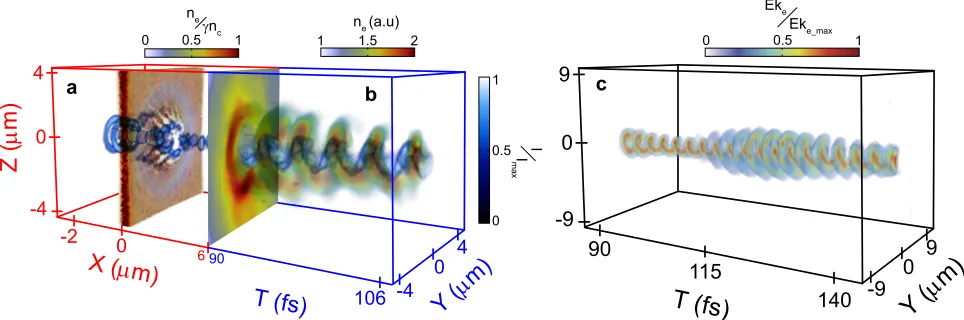
Figure 3: 3D PIC simulation results for circularly polarized light. a-b, Combined plot showing a, the
3D laser intensity profile (up to X=6 µm) at 100 fs, and b, temporal evolution of the electron density
distribution, overlaid with the laser intensity distribution, in the Y-Z plane at X=6µm from 90 to 107 fs.
c, Temporal evolution of the electron energy in the Y-Z plane at X=6µm up to 145 fs. The laser diffraction
lobe pattern rotates once per laser cycle driving an electron energy and density distribution which rotates
in phase with it. The rotational velocity imparted on the electrons drives their rotation after the laser pulse
0
-30
30 16
7.5
1
Y (
0o)
30-30 0
-30 30
Z (
o
)
Y (
0o)
30Y (
o)
-30 -30 0 30
2
1.5
1
d
e
a
b
c
Z (
o
)
f
84.5
1 1
0.55
0.1
n
e (a.u)
g
h
Y (
0o)
30-30
Σ
t
n
e (a.u)
1 2
[image:18.612.79.535.78.285.2]1 2
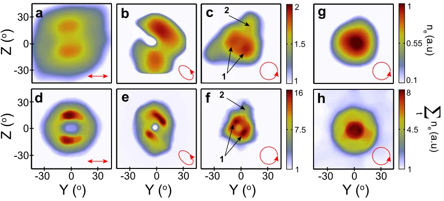
Figure 4:Experiment and 3D PIC simulation results for the electron density distribution.a-c, Electron
density as measured using image plate for electrons with energy greater than 3.5 MeV, with linear, elliptical
and circular polarized laser pulses, respectively. d-f, Simulated time-integrated electron density in the
plane Y-Z at 6 µm downstream from the rear side of the target, corresponding to linear, elliptical and
circular polarization, respectively. The electron energy distribution is integrated for ‘low’ energies (from
1-6 MeV).g-h, Corresponding experiment,g, and simulation,h, results for the circular polarization case
Z (
µ
m)
X (0µm)
-2 4 -3 3 0 1 0.5 0 0 3 -3 0 -3 3 120 60 0
Y (µm) X (µm)
Z ( µ m) 35 27.5 20 0 2 -2 0 -2 2
Y (µm)
7 3.5 0 0 3 -3 0 -3 3
Y (µm)
120 60 0 0 3 -3 0 -3 3
Y (µm) neγn
c 1
0.5
0
a
b
c
d
neγne
f
c
Σ
sne (a.u)Σ
sne (a.u)Σ
tne (a.u)Σ
tne (a.u)0
-2 4
-3 3
[image:19.612.125.488.74.333.2]0
Figure 5: 3D EPOCH simulation with laser focal spot size equal to 1.5µm and 6µm. a, Laser intensity
and electron density in the X-Z plane at Y = 0, for a 1.5µm (FWHM) focal spot. b, Y-Z plane withne/n
0
c
overlapped with the laser intensity profile (both spatially integrated over X = 0.7-1.5µm). c, Time
inte-grated electron density in the Y-Z plane at X=6µm. d-f, Same asa-cbut with a laser focal spot diameter
-1 -4
-4
-4 4
4
4 0
0
0
[image:20.612.142.470.75.296.2]7 0
|B| (kT) 10
Z (µm)
X (µm)
Y (µm)
Y (µm) |B| (arb.)1
0
0
1 2
3 4
5
6 a
b
Figure 6: Magnetic field structure driven by circularly polarized light. a, Magnitude of the magnetic
field driven by a circularly polarized laser pulse producing a relativistic plasma aperture in a 10 nm-thick
Al target. A helical field structure is produced. b, Same for the case of a lower intensity laser pulse
propagating through a fixed, predefined aperture of 0.75µm radius, i.e. without plasma effects. The 3µm
(FWHM) laser focus is centred on [X,Y,Z]=[0,0,0] in both cases and the field is sampled 30 fs after the peak
of the laser intensity. Diffraction induced by the aperture results in a helical field profile in both cases. The