Abstract—In this paper, a smoothly profiled horn was designed and manufactured to replace a corrugated output horn for a W-band gyro-TWA with improved ultra-high vacuum compatibility. It was optimized for high vacuum integrity, low reflection, high fundamental Gaussian mode content, low side lobe levels and high directivity over the frequency bandwidth of 90 - 100 GHz. Over this operating frequency band the reflectivity was better than -37 dB and the coupling to a fundamental Gaussian mode was above 97%. The far field pattern showed a directivity of approximately 27 dB in the measurement with side lobes lower than -30 dB.
Index Terms— horn, smoothly profiled horn, gyro-TWA, Gaussian mode.
I. INTRODUCTION
yrotron traveling wave amplifiers (gyro-TWAs), operating at mm-wave and sub-mm-wave frequencies have potential applications in radar [1], plasma diagnostics [2], remote sensing [3], for dynamic nuclear polarisation [4] and electron spin resonance spectroscopy [5]. A W-band gyro-TWA based on a helically corrugated waveguide [ 6, 7] is currently being experimentally evaluated for applications such as those mentioned above. The gyro-TWA is designed to amplify a 1 watt signal over the frequency range of 90-100 GHz, injected via an input coupler [8, 9], to yield ~3 kW output power when driven by a 40 kV, 1.5 A axis encircling electron beam. The experiment is based on a previous gyrotron backward wave oscillator (gyro-BWO) setup which achieved a frequency tuning band of 88 - 102.5 GHz and a maximum output power of 12 kW [10].
An output beam with a high coupling efficiency to a fundamental Gaussian mode is preferred for many applications. However, the output mode of the helically corrugated waveguide interaction region is TE11 in circular waveguide.
Therefore, an output launcher that converts the TE11 mode into
a quasi-Gaussian mode is required. We have previously This work was supported by the Engineering and Physical Sciences Research Council (EPSRC) U.K. under Research Grant EP/K029746/1, and Science and Technology Facilities Council (STFC) U.K. under Research Grants ST/K006673/1 & ST/K006703/1, ST/N002326/1 & ST/N002318/1. L. Zhang (liang.zhang@strath.ac.uk), W. He (w.he@strath.ac.uk), C. R. Donaldson (craig.donaldson@strath.ac.uk), and A. W. Cross (a.w.cross@ strath.ac.uk) are with Department of Physics, SUPA, University of Strathclyde, Glasgow, G4 0NG, Scotland, UK. G. M. Smith (gms@st-andrews.ac.uk), D. A. Robertson (dar@st-andrews.ac.uk) and R. I. Hunter (rih1@st-andrews.ac.uk) are with the SUPA, School of Physics & Astronomy, University of St Andrews, KY16 9SS, Scotland.
described the design of two high performance, broadband corrugated horn antennas as launchers for this application. The first one achieved 98% coupling to a fundamental Gaussian mode with reflection of -30 dB over the frequency range of 90 - 100 GHz [11]. The second design, integrated the corrugated horn with a multi-disk microwave window [12] to form the complete output launcher, and was able to achieve an improved output beam with 99.4% coupling to a fundamental Gaussian beam at 94 GHz [13]. As an output antenna this performance fully met the desired specification, but in subsequent experiments using the gyro-TWA, problems arose when the corrugated horns were used in an ultra-high vacuum environment. Corrugated horns were electroformed rather than directly machined and the combination of large surface area, due to the corrugations, and the electrochemically grown copper surface resulted in very long out-gassing times. To reduce the outgassing time, the vacuum system could be operated at a higher base pressure but this increased the risk of poisoning the thermionic cathode especially after activation.
To overcome this problem, whilst not compromising the electrical performance of the output assembly, a smoothly profiled horn has been designed and manufactured and is presented in this paper. The design requirements for this horn include: (1) ease of manufacture by direct machining, (2) vacuum compatibility, (3) return loss better than -30 dB, (4) directivity better than 25 dB, and side lobe level lower than -25 dB and (5) acceptably high coupling to a fundamental Gaussian beam, all over a bandwidth of 90 - 100 GHz.
II. SMOOTHLY PROFILED HORN
Fig. 1. The parameter definition of the profiled horn.
The profiled horn can be treated as a series of circular waveguides of different radii if the discrete section length is small enough, as shown in Fig. 1. The circular waveguide steps allow mode conversion between the input TE11 mode and the
TE1n and TM1n modes, hence generating a mixture of these
modes at the output aperture [14]. If the combination of the
Optimization and measurement of a smoothly
profiled horn for a W-band gyro-TWA
Liang Zhang, Wenlong He, Craig R. Donaldson, Graham M. Smith, Duncan A. Robertson,
Member
IEEE
, Robert I. Hunter, and Adrian W. Cross
[image:1.595.307.545.557.664.2]modes have the required amplitudes and phases, a field pattern similar to the fundamental Gaussian mode can be generated. A well-known example is the HE11 mode whose field can be
approximated by the combination of 85% TE11 mode and 15%
TM11 modes appropriately phased. This produces a
quasi-optical beam with ~98% Gaussian coupling to the fundamental mode, when a Gaussian mode set is chosen for the beam waist of 0.64Rap, where Rap is the radius of the aperture.
The scattering matrix of the waveguide step structures can be efficiently calculated by the mode-matching method [15, 16]. The overall scattering matrix of the whole horn structure can be obtained by cascading all the scattering matrices of the waveguide steps and the straight waveguide sections, hence the transmission and reflection of the modes can therefore be obtained. With given mode contents at the input port, the mode contents at the output aperture can therefore be calculated. The electric field at the output aperture of the horn can also be obtained which can be expressed as the sum of the TE and TM modes in the circular waveguide:
= ∙ ⃑
,
,
+ ∙ ⃑ (1) where and are the amplitudes of the TE and TM modes, respectively, and and are the corresponding phases of the modes.
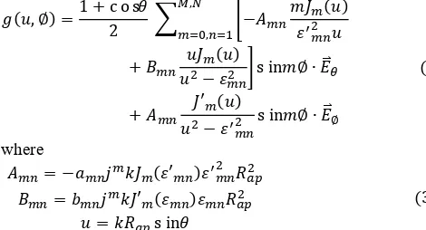
Various key parameters can be used to evaluate the performance of a horn, such as the gain or directivity, the far field pattern in E- and H-plane and the cross polarization. The normalized far field radiation pattern of the field at a circular aperture can be evaluated from the aperture field method, which is given by [17]
( , ∅) =1 + cos
2 −
( )
,
,
+ ( )
− sin ∅ ∙ ⃑ (2)
+ ′ ( )
− sin ∅ ∙ ⃑∅ where
= − ( ′ )
= ′ ( )
= sin
(3)
where k is the wavenumber in free space, and ′ , are the Bessel roots for the TE and TM modes, respectively. and ′ are the Bessel function of the first kind and its derivative, respectively.
In a circularly symmetric smooth horn with TE11 input mode,
there is only mode conversion between the TE1n and TM1n
modes. The E-plane far field pattern will be ( = /2) and H-plane far field pattern will be ∅( = 0). The directivity can
also be numerically evaluated from the far field electric field amplitude.
The reflection can be obtained from the scattering parameters, and the coupling coefficient of to the fundamental Gaussian mode can be calculated by Eq. 4. [18]
ϵ = ∬ ∙
∗
∬ ∙ ∗ ∙ ∬ ∙ ∗ (4)
It should be noted that ∬ denotes the integration is limited at the output aperture of the horn, while ∬ will integrate to infinity.
III. OPTIMIZATION OF THE SMOOTHLY PROFILED HORN Although all the aforementioned key parameters for an arbitrarily profiled horn can be obtained from the simulation process, it is not possible to directly determine a profile to fulfill all of these requirements. An optimization routine has therefore been used. In this paper, a global multiple-objective optimization method was employed [19]. Compared with single-objective optimization, the multiple-objective optimization allows more than one goal function to be optimized at the same time and provides better understanding of the relations among the goal functions. In a Potter horn [20], the goal is to optimize the phase and amplitude relationship between the TE11 and TM11 modes over a given frequency
range. In this design, the relative phasing and amplitudes of higher order modes are also included.
The variables, which generate the horn profile are the parameters to be optimized, and determine the excitation of higher order modes. There are many design choices for the horn profile optimization: conical horns [21], Gaussian-profiled horns [22], spline-profiled horns [23], Chebyshev polynomials profiled horns [24], arc-taper profile horns [25] and others [26] have all previously been suggested. In our design, we have chosen a horn profile based on the sinp function. The whole
profile is divided into two parts. The first part is defined by
R(z) = +( − ) ( )∙
2∙ ,
0 < < (5) where , and are defined in Fig. 2. It is then followed by a conical circular waveguide taper from radius to with a length of . The use of the linear taper section allowed a short nonlinear section which could be directly machined with less difficulty and cost. In this work, the input radius was determined by the output of the gyro-TWA, and was fixed as 2.8 mm. The output radius was determined by the existing multilayer microwave window and is 12.56 mm. Therefore only 5 parameters, including , , , and , need to be optimized. The value of and were set in the ranges 1.5 – 3.5 and 0.6-3.5, respectively. The range of the section lengths and were set in the ranges 45 mm - 120 mm and 35 mm – 170 mm, respectively. is between and .
[image:2.595.45.280.458.585.2]In theory, the multiple-objective optimization can optimize many goal functions simultaneously. However, the more goal functions there are, the slower the optimization routine reaches convergence. Practically, it is better to limit the number of goal functions to 2 or 3. Multiple parameters can be integrated into one goal function by assigning them with weights to reflect their priority. Highest priority was given to achieving low return loss and high coupling to the fundamental Gaussian mode, over the operating frequency range of 90 – 100 GHz. Therefore two goal functions were used in the optimization and their equations are expressed in Eq. 6.
Fun1 = ∑ ( , ) ∙ ( , ) ∙ ( )
Fun2 = ∑ ( ) (6) where are the discrete frequency points in the desired frequency range (90-100 GHz) used to calculate the coupling coefficient between the aperture electric field and the fundamental Gaussian mode. is the number of the frequency sample points. ( , ) is a penalty weight taking into account the corresponding Gaussian beam waist at frequency . If the beam waist is beyond the range 0.40Rap to 0.65Rap, ( , )
is assigned a value greater than 1. ( , ) is a penalty weight related to the directivity and the side lobe level. It will be greater than 1 if the directivity is smaller than 25 dB or the side lobes are higher than -25 dB. is the reflection of the TE11
mode. and are similar to and . In the simulation, = 20 = 1000 was used because when calculating the Gaussian percentage, the surface integration requires a lot of CPU time.
The final values of the parameters after the optimization were = 3.445, = 1.546, = 8.41 mm, = 50.5 mm and = 158.0 mm. Fig. 3 shows the simulated aperture electric field patterns at 90 GHz and 95 GHz. The electric field is slightly elliptical, however it is still close to the fundamental Gaussian mode. The field strength at the edge is small, which helps to reduce the reflection.
Fig. 4 shows the simulated coupling to the fundamental Gaussian mode as a function of frequency. There is a slight change in the ratio of beam waist to aperture radius, varying between 0.595 and 0.625 over the frequency range of 90 – 100 GHz. A coupling of nearly 99% is obtained at 95 GHz, whilst the minimum coupling to the fundamental Gaussian mode was about 97%. The simulated reflection of the TE11 mode was
below -56 dB. The far field calculation shows the directivity was about 26 dB, and the cross polarization level was below -25 dB.
(a) (b)
Fig. 3. The simulated electric field pattern at the aperture of the horn at (a) 90 GHz, (b) 95 GHz.
Fig. 4. The simulated coupling to a fundamental Gaussian mode, and the corresponding ratio of beam waist to aperture radius as a function of frequency, for the optimized smooth horn.
IV. CONSTRUCTION AND MEASUREMENTS
To manufacture the profiled horn it was made in two segments separated at the junction between the profiled part and the linear taper. The profiled section was directly machined from a copper rod by a precision computer numerical control (CNC) lathe. The tapered part was machined from a copper rod through electric discharge wire cutting. Then the two parts as well as the vacuum flanges were brazed together to form a single solid piece. The assembled horn together with a rectangular-to-circular converter and a waveguide taper used for the low power measurement by a vector network analyzer (VNA) are shown in Fig. 5(a). The horn with the microwave window was then vacuum sealed with the gyro-TWA experiment setup, as shown in Fig. 5(b). The final assembly was leak tested and held the vacuum to at least 1 x 10⁻⁹ mbar.
(a)
(b)
Fig. 5. The smoothly profiled horn connected to a rectangular-to-circular converter and a waveguide taper for microwave measurement (a), and vacuum test of the horn and the microwave window (b).
The measured results of the reflection of the TE11 mode for
[image:3.595.310.543.95.253.2] [image:3.595.305.550.485.680.2] [image:3.595.46.287.514.731.2]shown in Fig. 6. The measured reflection of the horn without the microwave window was lower than -37 dB over the desired frequency range 90 – 100 GHz. With the addition of the microwave window the reflection, while higher, was still lower than -32 dB. This satisfies the design requirements for the smoothly profiled horn.
Fig. 6. The measured reflection of the smoothly profiled horn with and without the addition of a multilayer microwave window.
The far field patterns of the smoothly profiled horn at 95 GHz are shown in Fig. 7. The directivity in the measurement was 27 dB and the side lobes were lower than -30 dB. The cross-polar level was -25 dB in accordance with simulations. The differences between the measurements and simulation were mainly caused by imperfect angular alignment of the measurement setup.
Fig. 7. The simulated and measured far field patterns of the smooth-walled horn connected with a multilayer microwave window at 95 GHz.
V. CONCLUSION
This paper has presented the design and experimental measurement of a vacuum-compatible, smoothly profiled horn for a W-band gyro-TWA. Over the desired operating frequency range of 90-100 GHz the horn achieved a very low input reflection of less than -37 dB and coupling to a fundamental Gaussian mode of over 97%, peaking at nearly 99% at 95 GHz. Additionally, the far field patterns measured at 95 GHz
demonstrate that the horn has a symmetric mainlobe and achieves side lobe lower than -30 dB. The cross-polar levels is below -25 dB. Whilst the optical performance of the smoothly profiled horn is slightly lower than achieved with our previous corrugated horn design, it has the significant advantages of vastly superior out-gassing properties and a quicker, lower cost manufacturing method. Thus the many previously discussed positive attributes of this type of horn make it a very appropriate choice as an output coupler for the millimeter wave gyro-TWA.
REFERENCES
[1] M. G. Czerwinski and J. M. Usoff, “Development of the haystack ultrawideband satellite imaging radar,” Lincoln Lab J., vol. 21, no. 1, pp. 28–44, 2014.
[2] S. Coda et al., “Electron cyclotron current drive and suprathermal electron dynamics in the TCV tokamak,” Nucl. Fusion, vol. 43, no. 11, pp. 1361–1370, 2003.
[3] W. M. Manheimer, G. Mesyats, and M. I. Petelin, pp.169-207 in Applications of High-Power Microwaves, A. V. Gaponov-Grekhov and V. L. Granatstein, Eds., Norwood, MA: Artech House, 1994.
[4] A. Feintuch, D. Shimon, Y. Hovav, D. Banerjee, I. Kaminker, Y. Lipkin, K. Zibzener, B. Epel, S. Vega, and D. Goldfarb, “A Dynamic Nuclear Polarization spectrometer at 95 GHz/144 MHz with EPR and NMR excitation and detection capabilities.”, J. Magn. Reson. Vol. 209, no. 2, pp. 136-141, 2011.
[5] E. A. Nanni, A. B. Barnes, R. G. Griffin, and R. J. Temkin, “THz dynamic nuclear polarization NMR,” IEEE Trans. Terahertz Sci. Technol., vol. 1, no. 1, pp. 145–163, Sep. 2011.
[6] G. G. Denisov, V. L. Bratman, A. W. Cross, W. He, A. D. R. Phelps, K. Ronald, S. V. Samsonov, and C. G. Whyte, “Gyrotron traveling wave amplifier with a helical interaction waveguide,” Phys. Rev. Lett., vol. 81,, pp. 5680–5683, 1998.
[7] L. Zhang, W. He, K. Ronald, A. D. R. Phelps, C. G. Whyte, C. W. Robertson, A. R. Young, C. R. Donaldson, and A. W. Cross, "Multi-Mode Coupling Wave Theory for Helically Corrugated Waveguide," IEEE Trans. Microw. Theory Techn., vol. 60, no. 1, pp. 1-7, Jan. 2012.
[8] L. Zhang, W. He, C. R. Donaldson, J. R. Garner, P. McElhinney, and A. W. Cross, "Design and measurement of a broadband sidewall coupler for a W-band gyro-TWA," IEEE Trans. Microw. Theory Techn., vol. 63, no. 10, pp. 3183-3190, Oct. 2015.
[9] J. R. Garner, L. Zhang, C. R. Donaldson, A. W. Cross, and W. He, "Design Study of a Fundamental Mode Input Coupler for a 372-GHz Gyro-TWA I: Rectangular-to-Circular Coupling Methods," IEEE Trans. Electron Devices, vol. 63, no. 1, pp. 497-503, Jan. 2016.
[10] W. He, C. R. Donaldson, L. Zhang, K. Ronald, P. McElhinney, and A.W. Cross, "High power wideband gyrotron backward wave oscillator operating towards the terahertz region," Phys. Rev. Lett., vol. 110, no. 16, p. 165101, 2013.
[11] P. McElhinney, C. R. Donaldson, L. Zhang, and W. He, "A high directivity broadband corrugated horn for W-band gyro-devices," IEEE
Trans. Antennas Propag., vol. 61, no. 3, pp. 1453-1456, Mar. 2013.
[12] C. R. Donaldson, P. McElhinney, L. Zhang, and W. He, "Wide-band HE11
mode terahertz wave windows for gyro-amplifiers," IEEE Trans. THz Sci. Technol., vol. 6, no. 1, pp. 108-112, Jan. 2016.
[13] P. McElhinney, C.R. Donaldson, J. E. McKay, L. Zhang, D. A. Robertson, R. I. Hunter, G. M. Smith, W. He, and A.W. Cross, "An output coupler for a W-band high power wideband gyro-amplifier,” IEEE Trans. Electron Devices, vol. 64, accepted, 2017.
[14] J. L. Doane, “Propagation and mode coupling in corrugated and smooth-wall circular waveguides,” in Infrared and Millimeter Waves, K. J. Button, Ed., New York: Academic, vol. 13, pp. 123-170, 1985. [15] G. L. James, “Analysis and design of TE11-to-HE11 corrugated cylindrical
waveguide mode converters”, IEEE Trans. Microw. Theory Techn., vol. 29, no. 10, pp. 1059-1066, 1981.
[image:4.595.50.287.465.623.2][17] A. Ludwig, “Radiation pattern synthesis for circular aperture horn antennas,” IEEE Trans. Antennas Propag., vol. 14, no. 4, pp. 434–440, Jul. 1966.
[18] P. F. Goldsmith, Quasioptical Systems: Gaussian Beam Quasioptical
Propagation and Applications. New York: Wiley, 1997, ch. 6.
[19] K. Deb, Multiobjective Optimization Using Evolutionary Algorithms. Chichester, U.K.: Wiley, 2001.
[20] H. M. Pickett, J. C. Hardy, and J. Farhoomand, “Characterization of a dual mode horn for submillimeter wavelengths,” IEEE Trans. Microw.
Theory Techn., vol. MTT-32, no. 8, pp. 936–938, Aug. 1984.
[21] A. D. Olver, P. J. B. Clarricoats, A. A. Kishk, and L. Shafai, Microwave
Horns and Feeds. New York: IEEE Press, 1994.
[22] A. A. Kishk and C.-S. Lim, “A comparative analysis between conical and gaussian profiled horn antennas,” Prog. Electromagn. Res., vol. PIER 38, pp. 147–166, 2002.
[23] C. Granet, G. L. James, R. Bolton and G. Moorey, "A smooth-walled spline-profile horn as an alternative to the corrugated horn for wide band millimeter-wave applications," IEEE Transactions on Antennas and Propagation, vol. 52, no. 3, pp. 848-854, Mar. 2004.
[24] B. M. Plaum, “Numerical optimization of smooth-wall and corrugated horn antennas,” 33rd Int. Conf. On Infrared, Millimeter and Terahertz Waves (IRMMW-THz), California, USA, Sept. 15-19, 2008.
[25] J. M. Neilson, “An improved multimode horn for Gaussian mode generation at millimeter and submillimeter wavelengths,” IEEE Trans.
Antennas Propag., vol. 50, no. 8, pp. 1077–1081, Aug 2002.
[26] G.G. Denisov, and S.V. Kuzikov, “Low-Lobes Antennas Based on Slightly Irregular Oversized Waveguides,” 20th Int. Conf. On Infrared and Millimeter Waves, Florida, USA, pp.297-298, W1.5, 1995.
Liang Zhang received the B.Sc. degree in applied physics from the University of Science and Technology of China, Hefei, China, in 2004 and the M.Sc. degree in application of nuclear techniques from the China Academy of Engineering Physics, Chengdu, China, in 2007, and the Ph.D. degree in physics from the University of Strathclyde, Glasgow, UK in 2012.
He is currently a Research Associate with the Scottish Universities Physics Alliance, Department of Physics, University of Strathclyde. His main research interests include pulse-power technology, and Gyrotron-TWA/backward-wave oscillators.
Wenlong He received the B.Sc. degree in physics from Soochow University, Jiangsu, China, in 1983, the M.Sc. degree in accelerator physics from the China Academy of Engineering Physics, Chengdu, China, in 1988, and the Ph.D. degree in relativistic electron beams and masers from the University of Strathclyde, Glasgow, U.K., in 1995.
He is currently a Senior Research Fellow with the Scottish Universities Physics Alliance, Department of Physics, University of Strathclyde. His main research interests include relativistic electron beams, Gyrotron-TWA/backward-wave oscillators, CARMs, FELs, and other high power microwave and terahertz devices.
Craig R. Donaldson received the B.Sc. (Hons.) degree in physics, the M.Sc. degree in high power RF and PhD. degrees from the University of Strathclyde, Glasgow, U.K., in 2005, 2006 and 2009, respectively, from the University of Strathclyde.
He has since continued to work as a Research Fellow with the Department of Physics, University of Strathclyde, with his main research interests in high frequency gyro-TWA/BWO's and electron beam generation.
Graham M. Smith was born in Karlsruhe, Germany in 1963. He received the B.Sc. degree (hons.) in theoretical physics from York University, York, U.K. in 1984 and the M.Sc. degree in lasers and opto-electronics and Ph.D. degree in millimeter-wave physics from the University of St. Andrews, St. Andrews, Fife, U.K. in 1985 and 1990 respectively.
He currently heads the Millimetre Wave and EPR Group, University of St. Andrews. His research interests primarily focus on the development of millimeter wave instrumentation and component design and systems for high-field electron paramagnetic resonance (EPR) spectroscopy, dynamic nuclear polarization (DNP) and other applications.
Dr. Smith was the recipient of the 2011 Silver Medal for Instrumentation from the International EPR Society for his work on high-power pulsed EPR.
Duncan A. Robertson (S’91–M’94) was born in Aberfeldy, U.K., in 1969. He received the B.Sc. degree (hons.) in physics and electronics and Ph.D. degree in millimeter-wave physics from the University of St. Andrews, St. Andrews, Fife, U.K., in 1991 and 1994, respectively. From 1994 to 1999, he was a Research Fellow with the Millimetre Wave Group, University of St. Andrews, under contract to DERA Malvern, working on battlefield millimeter-wave systems. Between 1999 and 2000 he was a Principal Microwave Engineer with Racal-MESL, Edinburgh, U.K., working on high power radar duplexers. From 2000 to 2004 he worked in the Photonics Innovation Centre, University of St. Andrews, commercializing millimeter-wave technology. Since 2004 he has been a Research Fellow with the Millimetre Wave and EPR Group, University of St. Andrews. His research interests include millimeter-wave radar, radiometry, imaging, electron paramagnetic resonance instrumentation, materials characterization (ferrites, dielectrics and absorbers) and antennas (corrugated horns, quasi-optics and non-mechanical beam steering).
Robert I. Hunter was born in St. Albans, U.K. in 1978. He received the M.Sci. degree (hons.) in physics and Ph.D. degree in millimeter-wave physics from the University of St. Andrews, St. Andrews, Fife, U.K. in 2000 and 2005 respectively. Since 2006 he has been a Research Fellow with the Millimetre Wave and EPR Group, University of St. Andrews working on instrumentation projects to develop a 94 GHz dynamic nuclear polarization (DNP) spectrometer and a high-power, pulsed 94 GHz electron paramagnetic resonance (EPR) spectrometer. His research interests include the characterization of ferrites, dielectrics and absorbing materials, the development of non-reciprocal ferrite devices for high performance quasi-optical systems and instrumentation for magnetic resonance applications.