Min Chen 1 and Zheng-Ming Sheng 1,2
1 Key Laboratory for Laser Plasmas (Ministry of Education) and Department of Physics, Shanghai Jiao Tong University, Shanghai, 200240, China and
2 SUPA, Department of Physics, University of Strathclyde, Glasgow G4 0NG, UK
In this chapter we describe and discuss a special technique in laser wakefield acceleration: electron injection by use of field ionization of atoms to high orders. Compared with other electron injection schemes in LWFA, this scheme shows the merits of relatively simple operation and controllable final beam quality. In the single-colorlaser ionization injection scheme, we show quasi-monoenergetic electron acceleration is possible through the control of laser self-focusing, which includes self-focusing accommodated ionization injection or ionization injection suppression, depending on the initial laser plasma parameters. In these processes the effective acceler-ation length can be controlled within a hundred micrometers range and the absolute energy spread of the beam can be controlled within tens of MeV. In thetwo-colorlaser ionization injection scheme, we show the effective
injection length can be furtherly reduced to tens of micrometers length, and the absolute energy spread of the electrons can be reduced to a few MeV, i.e. the relative energy spread can be less than 0.5% for a beam with peak energy of 350 MeV. A further interesting result is the generation of multi-color electron bunches by use of two-color lasers. These electrons can be used for multi-color X-ray generation through laser beam Thom-son scattering. It is also found that the transverse emittance of the electron beam can be significantly reduced by a different two-color ionization injection scheme, in which the wake excitation and electron injection are made by using lasers with different wavelength, respectively. The final transverse emittance of the beam can be less 10nm rad. Some recent progresses wordwide in experimental demonstrations of ionization injection are reviewed briefly with special attention to the beam quality improvement. Some prospects of ionization injection for practical applications in laser wakefield accelerators are also discussed.
PACS numbers: 52.38.Kd, 52.65.Rr, 41.75.Jv, 52.38.-r
I. PRINCIPLE OF IONIZATION INJECTION
Laser or beam driven wakefield acceleration as demonstrated in world wide laboratories is a very powerful and promising new technology for advanced electron acceleration, radiation source, therapy, and colliders [1–4]. Currently, one of the most challenging issues to overcome the limits towards applications is to substantially improve the beam quality. For stable, high quality, high charge beam acceleration both wakefield and electron motion process should be well controlled. Wakefield control is related to the laser driver control, including guiding and mode shaping. As for the electrons, besides the beam dynamics during the acceleration, the injection stage is tremendously important, which directly affects the final beam charge, energy spread and emittance and is therefore of primary importance.
As we know, besides the high acceleration gradient, the wakefield also has a very high phase speed (closed to the speed of light) and small spatial scale (tens of micro meters). To inject an electron beam into such a high speed small structure and make it to be trapped are extremely challenging. Many kinds of injection schemes have been proposed to pursue controllable injection. By adding a plasma density downramp region along the driver propagation path, the phase speed of the wakefield can be slowed down and then some of the background thermal electrons maybe trapped by the slow wave and then be accelerated to high energy. The other way for electron injection is to boost the speed of some of the background electrons. If the pre-accelerated electrons are faster than the wave when they are located at the end of the wake bucket, the electrons can be trapped inside of the bucket and be continuously accelerated until they enter into the deceleration phase. To this purpose, a few pre-acceleration mechanisms have been already considered. Among them, colliding pulse injection is the most promising method and it has already been extensively theoretically studied and experimentally demonstrated in several labs around the world [5, 6].
Here, besides the above mentioned two injection methods, we will introduce a third, simple injection mechanism i.e. ionization injection. Before the detailed analysis of ionization injection, let us recall the injection theory for one dimensional wakefield which was firstly described by Esareyet al.in 1995 [7]. In one dimensional approximation the trapping of a test electron can be well described by the HamiltonianH(γ, ψ)=γ−γββp−ϕ(ψ) or
H(u, ψ)=(γ2⊥+u2)1/2−βpu−ϕ(ψ) (1)
whereβis the longitudinal velocity of the particle normalized to c,u = γβis the normalized longitudinal momentum, βp ≃
1−ω2
p/2ω20 is the normalized phase velocity of the plasma wave, ψ = kpξ = kp(x−βpt) is the plasma wave phase with
kp = √
4πe2n0/m
ec2, andϕ=eΦ/mec2is the electrostatic potential of the plasma wave normalized to the electronic rest energy,
γ⊥=
√
1+u2
⊥is the transverse Lorentz factor andu⊥is the normalized transverse momentum of the electron,γ=
√
For an initially warm plasma,H=Ht≃1−βput, whereut≪1 is the initial non-relativistic thermal momentum. If the electrons
transverse momentum is 0, then trapping occurs forϕmin≤ −1+γ−p1+βput which sets a minimum intensity threshold for the
wake.
The wake potential is determined by the driver pulse and plasma parameters. In one dimensional geometry, the quasi-static laser driven plasma wave can be calculated according to the following equation:
∂2ϕ ∂ψ2 =γ
2p{β
p[1−
1+a2
γ2
p(1+ϕ)2
]−1/2−1}. (4)
wherea=eA/mc2is the normalized vector potential of the driver laser pulse and it can be calculated from the laser intensity (I) asa2=3.6×10⁻¹⁹(λ[µm])2I0[W/cm2], assuming circular polarization, whereλis the laser wavelength. A typical wakefield and its potential are shown in Fig. 1(a) by the red and blue lines, respectively.
Eq.1 to Eq. 4 give a full description of the wake excitation and particle dynamics for one dimensional wakefield acceleration. Ionization injection in one dimensional case can also be described by this theory. The ideal of ionization injection is firstly mentioned by Umstadteret al. in 1997 at the end of his paper on ponderomotive force injection, where he said that ”...Instead of using a fully ionized plasma (as above), one would use a medium with deeply bound inner shell electrons, which have an appearance intensity for tunneling ionization below that of the injection pulse but above that of the pump pulse ...” [8] The first detailed research work on ionization injection is done by Chen et al. in 2006 [9], where we used a double-pulse scheme. The first laser pulse works as a driver to excite a strong wakefield in a plasma, a second transversely propagated laser pulse ionizes the internal electrons of the high Z gas inside the wakefield at an appropriate time. In that paper, the contribution from ionization and ponderomotive force injections are compared in detail. Later on, the ionization injection scheme has been successfully generalized to a single laser pulse condition in which the wake excitation and ionization injection are performed by the same laser pulse. A lot of experimental studies have demonstrated this idea since 2010. Before that, ionization has already been used for electron injection inbeam-drivenplasma wakefield acceleration experiment.
Detailed 1D ionization injection theory for a single-pulse-driven injection scheme can be found in a paper written by Chenet al.[10]. The only difference with that theory is the nonzero component of the particles’ initial transverse momentumu⊥ which is usually negligible in a normal plasma wave. For an electron ionized inside the laser pulse in the 1D geometry, the transverse canonical momentum is conserved∂ψ =(u⊥−a⊥)=0. So for an electron ionized at a wake phaseψi,u⊥(ψ)=a⊥(ψ)−a⊥(ψi),
where we have assumed that the electron is born at rest, i.e. u⊥(ψi)=0. Once it leaves the laser fieldγ⊥ =(1+a2⊥(ψi))1/2. So
the Hamilton of the ionized electron isHi=γ⊥(ψi)−ϕ(ψi)=1−ϕ(ψi). The trapping condition is
−(ϕ(ψi)−ϕmin)≥1−(1+a2⊥(ψmin))1/2/γp, (5)
which assumes that the laser pulse has zero intensity at the trapping position i.e.,a⊥(ψmin)=0. The left side of the in-equality
represents the maximum energy that the electron can get from the wakefield after its ionization. It needs to be larger than a threshold value determined by the wake properties (seeγp). Usually the wake itself determinesϕminandγp. By using a mix
of different gases, including high Z gas, the ionization positionψican be controlled. If ionization happens at a position with
large wake potential, the trapping condition can be satisfied. Common gases such as Nitrogen, Oxygen, Argon can be used in mixtures for such kind of injection. A typical process is shown in Fig.1 in which the sixth and seventh electrons of Nitrogen are used for injection. The first five electrons are ionized in the early rising edge of the laser pulse where the wake potential is almost 0. The last two electrons are ionized near the pulse peak at a position where the wake potential is high. The green line shows the distribution ofHs−Hfor the electrons ionized at different positions. Electrons ionized whereHs−H >0 satisfy
(a) (b)
FIG. 1: Schematic view of ionization induced injection. (a)Analytical results for 1D ionization injection. Normalized laser vector potential (light blue/gray curve), wake potential (blue/up dark gray curve), wake electric field (red/lower gray curve),Hs−H(green/middle gray curve),
and degree of ionization versusξ/λp. The dashed black curve shows the degree of ionization forN4+ → N5+, and the solid black curve
showsN5+ → N6+. (b)2D-PIC simulation results of ionization induced injection. Typical trajectories of trapped electrons via ionization.
Laser-plasma parameters area0=2.0;LFW H M=14.89T0, focus spot sizeWFW H M =17.66λ0, uniform plasma density withne=0.001nc, and
mixed gas lengthl=20λ0. The Nitrogen concentration is 1%. Top half showst=80T0and bottom half showst=400T0.
can see the injected electrons to be injected are ionized closed to the peak of the laser pulse where the wake has a suitably high potential. Actually some of the electrons are ionized off-axis. This gives another source of transverse emittance in addition to theu⊥from ionization process.
Compared with a normal injection theory, the trapping condition is modified by including the effect of the residual transverse momentum resulting from the ionization process (seea⊥(ψmin)). As we will show later it is just because of this residual
mo-mentum that electrons injected by ionization may have large transverse emittance. By using two-color laser pulses to separate wake excitation and injection processes, one can overcome this problems. Since the whole process involves many nonlinear phenomenons, such as laser propagation, wake excitation, ionization, electron trapping, and so on, a simple analytical theory cannot give correct and detailed information. Computational simulations and experiments are the main tools to study these pro-cesses. In the following we will discuss a variety of ionization injection schemes to obtain high quality (low energy spread, low transverse emittance) electron beams. Finally, we will show some recent experimental and theoretical progresses on this topic.
II. USING IONIZATION INJECTION TO GET LOW ENERGY SPREAD ELECTRON BEAMS
From above analysis, one can see that ionization injection is a relatively easy scheme to inject electrons in a wakefield. No external laser pulse or gas jet need to be installed. Just by mixing some high Z gas in He gas may lead to ionization injection once the laser and plasma have appropriate parameters. A few earlier experiments have already demonstrated this scheme. However, the final accelerated electron beam quality is not as good as other injection schemes [6]. The spectrum always shows a tail in the low energy part. The reason is that usually the laser pathLin jectioninto the mixed gas is larger than 1-mm. For electrons injected in
wakefield, the distances between the initial injection positions can result in a big final energy spreadδε, with a maximum energy difference ofδεM=E
x×Lin jection. Usually the wakefield amplitudeExis∼GeV/cm, so 1-mm separation in the injection distance
leads to 100 MeV energy difference. To reduce the absolute energy spread, effective injection length should be controlled and kept as short as possible. In this section two schemes are aimed to decrease the effective injection length. The first one is by using the self-evolution of the wakefield due to the unmatched laser pulse: the injection is switched offby varying the wake parameters out from the injection condition range. The second is by controlling the ionization itself through laser electric field intensity modulation. Both of them can lead to mono-energetic electron spectrum. The second way is able to reduce the energy spread down to less than 1% and can also provide multi-color electron bunches.
A. Self-truncated ionization injection
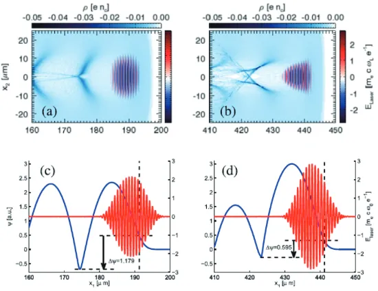
FIG. 2: (a) and (b) Electron density and laser electric field distribution at the laser propagation distance of 200 and 450µm, respectively. (c) and (d) Laser (red lines) and pseudo-potential (blue lines) line-outs at these two time steps. Densities are normalized byncand electric fields
are normalized byE0 =mecωLe−1 =1012V/m. The dashed lines show the ionization starting point of nitrogen inner shell and the fall to the
bottom of the potential well (∆ψ=1.179 and 0.595, respectively).
FIG. 3: (a) Injected charge number vs. laser propagation distance from 2D PIC simulations with different normalized laser vector potentiala0
and normalized waistkpW0. The laser energies are kept the same in 2D slab geometry by keepinga20W0a constant. (b) Laser peak amplitude
evolution of two cases: black line fora0=2.4,kpW0=5.27 and green line fora0=3.2,kpW0=2.97. The red dashed lines indicate the region
where the injection is suppressed for the black line case.
FWHM energy spread. To illustrate this mechanism a series of 2D simulation results are performed, a typical result is shown in Fig. 2. In the simulations a 800nm laser pulse with vector potential ofa0 =2.0, waist ofkpW0 =7.594, pulse duration of
LFW H M =33f sare used. The background plasma density is 1.6×10⁻³ncand mixed nitrogen atom density is relatively small
and varies from 5×10⁻⁶to 1×10⁻⁴. Snap shots of wakefield and laser pulse at two different acceleration distances are shown. At aboutx=190µm, the ionization injection condition is satisfied with∆ϕ =1.179>1. However at the distancex≈440µm
the laser pulse is self-focused and the corresponding wake evolves significantly which makes∆ϕ=0.595<1 and the injection condition has been broken. Thus the injection is self-truncated by the laser and wakefield evolutions. In this way the effective injection length is not determined by the mixed gas length (usually in the scale of mm) but it is determined by the laser evolution time-scale which is in this case around 200µm.
[image:4.595.171.446.56.268.2] [image:4.595.148.474.342.465.2]FIG. 4: Schematic view of dual color lasers trigged periodic injection in LWFA. A laser with base frequencyω1 (the red curves) and its
harmonicω2(the blue curves) propagate in a mixed gas plasma. The dashed black curves show the superposition of the two frequency laser
fields at different propagation distances. Laser parameters are chosen so that ionization-induced injection can be switched on when the beating is constructive and be switched offwhen the beating is destructive. In the plot,Eithrepresents the effective threshold field for the high-Z gas
inner shell ionization.
self-truncated and finally a second injection happens. The final spectrum shows two peaks, each one with narrow energy spread. Combining this technique with shortening (by mechanical fabrication) of the laser path in the gas-mix, electron spectrum with a single quasi-monoenergetic peak is possible. 3D-PIC simulation done by Zenget al.proved how effective such a scheme can be [12]. A recent experiment done by Liet al. demonstrate this scheme. Monoenergetic electron beam with energy spread of 10% and central energy of 400 MeV are reported [13].
B. Two-color ionization injection
The above self-truncated injection scheme provides a simple way for mono-energetic electron beam acceleration. However, since basically it relies on laser self-focusing it is a not well controllable method to get stable acceleration. Further, the energy spread is still too large for many applications. Besides controlling the wake properties, the other way is to control the ionization process. Xia et al. have used this to control ionization injection [14]. However in their case, the wake evolution effect is small. The laser intensity is tuned around the ionization threshold. Only when the self-focusing happens internal electrons of the injection gas are ionized and injected. Such process can also be used for mono-energetic beam acceleration. However, it is more difficult to tune the laser energy and the energy spread is still relatively large.
A two-color ionization injection scheme is recently been proposed by our group [15]. The idea is schematically shown in Fig. 4. Two laser pulses with vector potential of ai(z,t) = ai0sin(ωit−kiz+ϕi), (i = 1,2) are used to excite the wake and
trigger ionization injection, respectively. The injection pulse is a frequency-tripled laser. As two color pulses copropagate in the background plasma, the peak amplitude of the combined laser field is modulated in time and space during the laser propagation due to the plasma dispersion (ω2
i = ω
2
p+c2k2i). Ionization injection only occurs when the peak amplitude exceeds a certain
threshold. The threshold is exceeded for very short duration periodically at different propagation distances, leading to multiple ionization injections and separated electron bunches.
The combined laser electric field of the two pulses can be rewritten as
E(ξ,s)=a10cos(ξ+ω2ps/2+ϕ1)+a20ω2cos(ω2ξ+ω
2
ps/2ω2+ϕ2), (6)
whereξ=ω1(t−z/c) ands=ω1z/c. One can see that the electric field is a periodic function ofsandξand the period of s is ∆s=4π/ω2
p(ω2−ω−21). Similarly to the peak amplitude evolution of the two color pulse, the ionization injection region can be broken into small pieces. By appropriately selecting the amplitude and the frequency of the two pulses, ionization injections can be limited to a few small separated regions. Zenget al.has shown typical simulations for this scheme in their papers published in Physical Review Letters [15]. In the scheme they used Nitrogen as injection gas and laser pulses with 800 nm and 266 nm wavelengths, respectively.
A typical 2D simulation is shown in Fig 5, where laser parameters are: a10 = 1.46,a20 = 0.162,LFW H M = 33fs,W0 =
80µm,ne =1.6×10⁻³nc,nN =1.6×10⁻⁷nc. The injection stage length (the length of mixed nitrogen) isLin j = 1mmwhich
FIG. 5: 2D PIC simulations of the two-color ionization injection injection scheme. (a) The density snapshot atz =3780µm. The colored dots show the locations of three electron bunches. (b) The energy and space distribution of the energetic electrons. (c) The spectrum of the injected electrons, showing three monoenergetic peaks. (d) The pseudopotential (ψ) difference of the wake and the laser peak field evolution. The dash-dotted line is the separation from the mixed gas region to the pure helium region.
that within the second and the third bunches there are a few micro bunches which come from the overlapping of several peaks when the combined electric field is larger than the ionization threshold as schematically shown in Fig. 4. These bunches degrade the monochromaticity of the final beams, showing the pedestals between the peaks of the energy spectrum in Fig. 5(c). From the simulations they found that those pedestals can be reduced by using a shorter triple frequency laser pulse, which makes the inner shell ionization occurring only in a single peak. A simulation with a 10 fs, 3ωlaser gives a single injected electron bunch with final energy spread less than 0.2% FWHM. In the simulation of Fig. 5, the whole spectrum is composed of three main peaks with equal separation of 30 MeV. The ionization injection analysis is shown in Fig. 5(d). The mixed gas locates on the left side of the dashed line. The intensity of the combined laser electric field is shown by the red curve. The pseudopotential differences and the threshold for ionization injection are shown by the black solid and blue dashed lines, respectively. The former is automatically set to be zero if ionization cannot occur. As one can see, ionization injection only happens in three regions, namely around the beginning, at about 500µm, and 1000µm. Each one occurs in a very limited region (tens of micrometers). This is consistent with the three injected electron bunches labeled by 1,2,3 in Fig. 5(a,b,c). More 3D simulations also demonstrate the effectiveness of such scheme. More detailed information can be found in Ref. [15].
Besides the extreme low energy spread of the electrons injected and accelerated by the above two-color ionization injection method, the scheme is also unique for generating multichromatic narrow energy-spread electron bunches which can be used for multi color x-ray generation through Thomson Scattering scheme. These are interesting for medical or material imaging applications. The multichromatic beams may also be interesting for radiotherapy. From comparing the characteristics of radio physics of the multi-fields full body irradiation by mixed-energy electron beam with single-energy electron beam, results show that multi-chromatic energy electron beams can not only meet the clinical treatment requirements for treating mycosis fungoides, but also shorten the treatment time compared to the single-energy electron beam radiation treatment [16]. The current challenge is to reduce the electron energy from 100 MeV to a few MeV level [17].
III. USING IONIZATION INJECTION TO GET LOW TRANSVERSE EMITTANCE ELECTRON BEAMS
As we mentioned before, electrons ionized inside the laser pulse may carry a residual transverse momentum from ionization. These momenta increase the final beam transverse emittance (εN∼γrbp⊥/p∥ =rbpˆ⊥), whererbrepresents the transverse beam
FIG. 6: (a) The electric field of the laser pulses (green curve is on-axis laser field profile), (b) the longitudinal wakefield (green curve is on-axis wakefield), and (c) the transverse phase space of the injected electrons, after the (mixed gas) ionization injection region. (d) The normalized transverse emittanceεN(red solid curve) and trapped electron number N (black dashed curve) versus the injection pulse amplitudea1. See text
for laser-plasma parameters.
are possible methods to lower the final beam emittance. In the following two corresponding schemes are introduced to get low transverse emittance within an ionization injection configuration.
A. Two-color ionization injection
From Eq. 4 one see that a driver pulse with larger vector potential (a) can excite a stronger wakefield. This looks in con-tradiction with the low transverse emittance requirement (see beforeu⊥(ψ)=a⊥(ψ)−a⊥(ψi)). However, if one uses two laser
pulses to separate wake excitation from ionization injection, the contradiction no longer exists. Such scheme has recently been studied by Yuet al.[18] and Xuet al.[19]. In their scheme a low frequency (large wavelength, such asλ0=5µmorCO2laser λ0=10.6µm) laser pulse, is used for wake excitation. Since the laser vector potential isa= √I(w/cm2)/1.38×1018λ(µm), for a fixed laser pulse intensity, the longer the wavelength the larger the vector potential, which is better for wave excitation. On the contrary, a high frequency laser pulse is used to trigger ionization injection. This is because fromE∝∂A/∂tone getsa∝E/λ
and for similar ionization degree (similar electric field intensity E) the larger the wavelength the smaller the vector potential, which is better for keeping a small residual transverse momentum.
A typical two dimensional simulation of this scheme by Yuet al.is shown in Fig. 6. In the simulation Kr is used as injection gas.The electron density (after ionization by the pump laser) is fixed ton0=ne+8nKr=2×1017cm−3, whereneis the electron
density produced by ionization of the low-Z background gas (e.g. He gas), and the pump laser ionizes the Kr gas toKr8+. The Kr gas locates fromz=−100µmtoz= 0µm, with a plateau of 50µmbordered by two ramp-like density profiles. The pump and injection pulses have the normalized vector potential likea(ξ)0,1 = a0,1exp[−(ξ−ξ0,1)2/L20,1], with amplitudesa0 =1.17 anda1 = 0.135, wavelenghts λ0 = 5µmandλ1 = 0.4µm, durations (FWHM) T0 = 92f sandT1 = 16f s, and spot sizes
w0 = 36µmandw1 = 5µm, respectively. Different from the two-color scheme we discussed above to get low energy spread electron beam, here the two pulses are not overlapped with each other but they are separated by an optimal delay corresponding to|ξ0−ξ1|=106.25µm. So the electrons ionized by the second pulse are located in the trapped orbit of the wake excited by the first pulse.
[image:7.595.143.467.60.345.2]lon-gitudinally accelerated by the wake (see Fig. 6(a,b)). The transverse phase-space distribution of these electrons are shown in Fig. 6(c). As we can see most of the electrons have zero residual transverse momentum. This is because they are usually ionized at the peak of the injection laser electric field, where the laser vector potential is zero for a normal single color Gaussian pulse. Electrons ionized just off-peak of the laser electric field are trapped and produce the finite transverse momentum. The maximum momentum in Fig. 2(c) ispx/mec≃0.17, which is larger than the vector potential amplitudea1due to the effects of the trans-verse force of the wakefield and transtrans-verse ponderomotive force of the injection laser pulse. The rms beam radius and transtrans-verse momentum areσx≃0.55µmandσpx/mec=0.05, respectively. Hereσpxis an order of magnitude smaller than that observed in
simulations of single-pulse ionization injection. The final transverse emittance of the electrons isεn=0.028mmmrad.
Similar idea was also studied recently by Xuet al.[19]. Instead of 5µmdriver pulse, they used CO2laser as a driver pulse. However, the basic idea is exactly the same. Detailed information can be found in Ref. [19].
B. Ionization injection assisted by transverse colliding pulses
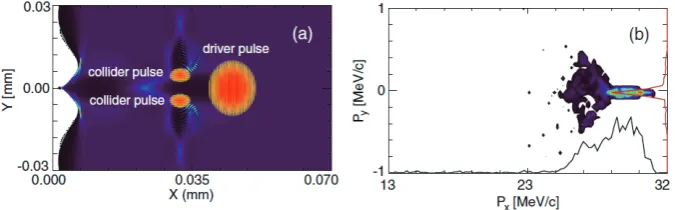
As we see before the ionization induced transverse emittance is due to the transverse residual from the injection pulse gen-erated during ionization. One may think that if this momentum is not fully transverse the emittance may be reduced. A recent modified ionization injection scheme proposed by Chenet al. just uses this idea [20, 21]. The idea is schematically shown in Fig. 7(a). A driver pulse first excite a wave in the background plasma, then two identical frequency transverse laser pulses with polarization parallel to the driver pulse propagation direction are oppositely injected and overlapped at an appropriate phase of the wake. The combined laser field of the two transverse pulses is high enough to ionize the internal electrons of the injection gas (e.g. Nitrogen). Since the vector potential of the two pulses are along the longitudinal direction of the wake, the residual momentum is along this direction and no transverse momentum is introduced.
Chenet al. have studied this scheme by using 2D particle-in-cell simulations. A driver pulse with length of L0 = 6.0T0, transverse size ofW0 =10λ0and intensity ofa0=1.5 is used. The injection pulses have temporal duration ofL1 =L2 =3.0T0 and transverse sizes ofW1 = W2 = 3.0λ0. They have the same wavelength as the driver pulse (λ0 = 0.8µmand intensities
a1 =a2 =0.8. They collide with each other at the axis of the driver pulse propagation and at an optimal delay with the driver pulse which makes the electron injection possible. The background plasma has a density ofnpre−e =0.001nc. The density of
the injection gas (Nitrogen) isnN=2.0×10⁻⁶nc. Simulation results shown 6.38×10⁶/µmelectrons have been injected into the
second wave bucket. The final beam transverse full-with-at-half-maximum (FWHM) momentum spread is 0.1mecas shown in
Fig. 7(b). The beam is quasi-monoenergetic with the peak energy of 29.32MeV and FWHM energy spreadδE≃3.84MeV. The transverse momentum spread is an order smaller than the one by using an usual single pulse ionization injection scheme. Further optimal simulations show the minimum transverse emittance of the electron beam injected by this method can be as small as 0.08mmmradwhich is far less than the normal value of 1mmmrad.
It deserves to point out that, besides ionization induced electron injection into the wakefield, the transverse ponderomotive force of the two pulses may also lead to ponderomotive injection which is similar as the scheme proposed by Umstadter in 1996 [8]. To increase ionization injection percentage one needs to use two transverse laser pulses with identical frequency, oth-erwise transverse beat wave will be generated which accelerates electrons transversely, resulting in a high transverse momentum of the electrons. Two pulses with different frequency may be used to increase the transverse momentum of the injected electron beam to make stronger betatron radiation.
[image:8.595.140.478.52.157.2]FIG. 8: (a)Raw electron data from for Claytonet al.’s experiments [26]. (b) Energy spectrum for the three features in the energy measurement.
injection. This makes the final transverse electron beam emittance even smaller. In their studies ultrashort (∼8f s) high-current (0.4 kA) electron bunches with a normalized emittance of 8.5 and 6 nm in the two planes, respectively, and a brightness of 1.7×10¹⁹Arad−2m−2can be obtained for realistic parameters [22].
IV. WORLDWIDE IONIZATION INJECTION DEMONSTRATION EXPERIMENTS
In the previous sections, we introduced ionization based electron injection from analytical and simulation points of view. Almost at the same time of the theoretical progress, ionization injection has been experimentally demonstrated and optimized both inlaser-drivenandbeam-drivenwakefield acceleration. To our knowledge the first intentioned experimental studies of ionization injection in wakefield acceleration is by Ozet al.[23], where the wakefield is driven by an electron beam of 28.5 GeV energy in a Lithium vapor column. Li plasma electrons act as the background electrons and support the wake. The doped Helium atoms are used as the ionization injection source since the higher ionization potential of He atoms makes them being ionized only inside the wakefield. As the wake amplitude is increased, the ionization induced Helium electron trapping is observed. Some electrons gain up to 7.6 GeV energy in a 30.5 cm plasma. After that the ionization injections inlaser-drivenwakefield were also reported by three groups independently in 2010 [24–26].
Paket al. [24] observed continuous ionization injection in their experiment above an initial laser intensity threshold (e.g.
a0 =2.35, still less than the laser intensity threshold for self-injection) and electrons with maximum energy up to 110 MeV were observed. The injection is due to the ionization of K-Shell of nitrogen in a He background plasma. Reducing the laser intensity toa0=1.64 the low energy part of the spectrum disappeared and quasi-monoenergetic spectrum appeared due to the ionization stopping because of the lower laser intensity after some propagation. However, the spectrum was still very broad.
McGuffeyet al.[25] used targets composed of helium and controlled amounts of various gases. In some of their experiments with laser power of 30TW and 120TW level, they found the addition of a higher Z additive (such as Ar, N2, Ne) can increase the beam charge by as much as an order of magnitude compared to pure helium at the same electron density and decrease the beam divergence from 5.1±1.0 to 2.9±0.8 mrad. Their simulations for the experiments showed that electron beams with energy up to 150MeV were generated. The spectra were basically broad (more than 20%).
By using higher laser power (60fs, 110TW) and longer acceleration length (1.3cm), Claytonet al.[26] accelerated electrons up to 1.45GeV in a regime of matched-beam, self-guided laser propagation and ionization-induced injection. They used 3% amounts ofCO2 gas as injection gas. The background plasma density from He is 1.3×1018cm−3. At this low density and fora0 ≤ 4, only electrons born inside the ion bubble are expected to be trapped via ionization-induced injection. Computer simulations confirmed that it is the K-shell electrons of oxygen that are ionized and injected into the wake and accelerated to beyond 1 GeV energy. The spectrum again shows very broad character as shown in Fig. 8 (see beam k).
[image:9.595.146.474.53.291.2]Pol-FIG. 9: Simulation results show how an electron driver ionizes Li gas and generates a Li blowout with an electron density ofne(Li) =
3.3×1017cm−3. The Ti:sapphire laser pulse with a duration of 8fs anda
0 =0.018 is located at the end of the first half of the blowout at the
electric fields turning point, and has already ionized some He electrons, which are then trapped and accelerated.
lock [28]) have used a similar scheme to separate ionization injection stage from acceleration stage and obtained quasi-monoenergetic electron acceleration. In Liu’s experiment [27], electrons with a Maxwellian spectrum, generated from the first LWFA assisted by ionization-induced injection, were seeded into the second LWFA with a 3-mm-thick gas cell. The first stage was 1-mm thick and filled with 6% oxygen gas and 94% helium gas flow, the second stage with variable thickness from 1 to 3mm was filled with pure He gas. The 40∼60 TW laser pulses were used in the experiments. The plasma densities were
∼5.7×1018cm−3in the first gass cell stage and∼2.5×1018cm−3in the second one, respectively. Finally a quasi-monoenergetic electron bunch peaked at an energy of 0.8 GeV was observed with 25% energy spread, 2.6 mrad divergence, and∼3.7pCcharge. In Pollock’s scheme [28], the gas cell is comprised of a 3 mm injection stage, filled with a mixture of 99.5% helium and 0.5% nitrogen gas, separated by a 1 mm diameter aperture from an immediately adjacent 5 mm acceleration stage containing pure He. Plasma density of 3×1018cm−3 in each stage for a coupled laser power of 40 TW were used. Finally a 460±25MeV electron beam containing∼35pCof charge was observed. PIC simulations for both these two experiments show that ionization induced injection is the main mechanism for electrons trapping in the wake in the first stage. The following acceleration stage is only used to boost the beam energy and reduce the relative energy spread. However, due to the large thickness of the first gas jet, electron beams injected by this two stage scheme are inevitably with large absolute energy spread as we mentioned before. Two-color ionization injection scheme may solve this issues. However, no experiments on this have been reported yet.
At last, we mention that recently in the laboratory for laser plasma at Shanghai Jiao Tong university, an experimental group has obtained quasi-monoenergetic electron beam with central energy of 1.14GeV energy spread of 7% from a single stage by using self-truncated ionization injection scheme which was discussed before in Section II B [29]. A preliminary result from the same group was recently published in Optics Express [13]. They use a mixed gas with 0.3% nitrogen and 99.7% helium gas. Upon the interaction of 30-TW, 30-fs laser pulses with a gas jet of the above gas mixture,> 300 MeV quasi-monoenergetic electron beams were generated at a plasma densities of 3.3−8.5×1018cm−3.
V. FURTHER DEVELOPMENT OF IONIZATION INDUCED ELECTRON INJECTION
Due to the relatively simple experimental operation and flexible tunability, ionization injection is suggested as a very promis-ing injection scheme in LWFA. Besides the above mentioned researches, it has also been modified and improved for other applications.
Hiddinget al. recently has proposed a concept named plasma photocathode emission and used it in a beam-driven plasma blowout regime as shown in Fig. 9 [30, 31]. The scheme is similar as the one we mentioned before for low emittance beam generation by using two-color laser pulse. The difference is that in the current scheme the first driver laser pulse is replaced by a relativistic electron beam with charge of 300pC and energy of 200MeV. Same as the first ionization injection demonstrated experiment, the background is a Lithium plasma with density of 3.3×1017cm−3and the injection gas is Helium. So a very low laser intensity (a = 0.018) can be used to ionize He and make electron injection. In their simulation they found a beam with normalized emittance ofεN ≃4×10⁻⁸mradcan be obtained, which opens up the possibility of its applications in future laser
plasma accelerator based free electron x-ray lasers (FEL).
[image:10.595.186.434.52.202.2]the driving laser pulse can be guided in a plasma channel or a hollow capillary waveguide, allowing the trapped electrons to be accelerated to high energy. Particle-in-cell simulations show controlled injection and acceleration of electrons to an energy of 370 MeV, a relative energy spread of 2%, and a normalized transverse emittance of 2.0µm.
The final electron emittance not only depends on the initial injection process, but also on the following electrons’ dynamics in phase space (mainly affected by Betatron motion). By using theory and PIC simulations, Xuet al. have recently studied phase-space dynamics of electrons injection by ionization mechanism in plasma-based accelerators [33]. They found that the injection process involves both longitudinal and transverse phase mixing, leading initially to a rapid growth of emittance and following oscillations, decay and a slow growth up to saturation. Electrons ionized at the same time can reside over a large range ofψof the wake, and thus feel a range of longitudinal wakefieldEx. The difference ofExcause the longitudinal phase mixing to
the ionization injected electrons because of different Betatron frequency. Electrons ionized at different times (tion) can also reside
within the same longitudinal beam slice. Transverse mixing can occur within a slice due to the different phase-space distributions including different initial energies of the electrons after injection. These two phase mixing processes are responsible for the complex emittance dynamics. From theory and simulations they also found an optimal acceleration distance (x0=(Ex/σEx)σx)
to achieve minimum emittance for the trapped electrons, whereσ2
x=<(si−<si>)2>andσ2Ex =<(Ex−<Ex>)
2>,s
iandEx
represent the ionization position and the local wakefield intensity, respectively.
VI. CONCLUSION
In this chapter, we have introduced a relatively simple electron injection method in laser wakefield acceleration, which relies on the ionization of the inner shell electrons of a High Z gas. These electrons are protected by the mother ions while passing through the deceleration phase of the wake. When they arrive at the appropriate phase of the wake they are ionized by the strong laser electric field there and then are trapped in the wake for following acceleration. Improved ionization schemes such as the two-color scheme and the transverse pulse ionization injection scheme are proposed by several groups to reduce the final energy spread and transverse emittance of the accelerated electron beams. Although such schemes can improve some aspects of the qualities of the beams, none of them can make simultaneous high quality for both longitudinal and transverse emittances. More theoretical and experimental investigations are necessary to make the LWFA beam appropriate for wide applications, such as new generation radiation source, TeV collider, and so on. Especially for external beam radiotherapy applications, the challenge is to produce a mount of high quality low energy electron beams. For this purpose, high repetition low power laser driven wakefield acceleration may be a better selection, in which ionization injection is also a good scheme since it can separate the high quality injection process from the acceleration process. At the same time, the high energy photon radio therapy such as X rays orγrays can also benefit by the ionization injection scheme. Electrons with high quality can radiate X rays through betatron oscillation [4], plasma channel guided oscillation [34] or Bremstrahlung radiation. For this purpose more work of improving the yield and quality of the radiations should be done.
Acknowledgments
This work was supported by the National Basic Research Program of China (Grant No. 2013CBA01504), the National Natural Science Foundation of China (Grant Nos. 11421064, 11374209, 11374210 and 11405107), the MOST international collaboration project (Grant No. 2014DFG02330). M.C. appreciates supports from National 1000 Youth Talent Project of China.
[1] E. Esarey,et al.Rev. Mod. Phys.81, 1229 (2009). [2] W.P. Leemans, and E. Esarey, Phys. Today62, 44 (2009). [3] S.M. Hooker, Nature Photon.7, 775 (2013).
[4] S. Corde,et al.Rev. Mod. Phys.85, 1 (2013). [5] E. Esarey,et al.Phys. Rev. Lett.79, 2682 (1997). [6] J. Faure,et al.Nature431, 541 (2004).
[7] E. Esarey, M. Pilloff, Phys. Plasmas2, 1432 (1995).
[8] D. Umstadter, J.K. Kim, and E. Dodd, Phys. Rev. Lett.76, 2073 (1996). [9] M. Chenet al., J. Appl. Phys.,99, 056109 (2006).
[10] M. Chenet al., Phys. Plasmas19, 033101 (2012).
[11] S. Kalmykov, S. A. Yi, V. Khudik, and G. Shvets, Phys. Rev. Lett.103, 135004 (2009). [12] M. Zenget al., Phys. Plasmas21, 030701 (2014).
[30] B. Hidding,et al., Phys. Rev. Lett.108, 035001 (2012). [31] Y. Xi,et al., Phys. Rev. ST Accel. Beams16, 031303 (2013). [32] N. Bourgeois,et al., Phys. Rev. Lett.111, 155004 (2013). [33] X.L. Xu,et al., Phys. Rev. Lett. 112, 035003 (2014).
[34] M. Chen, J. Luo, F.Y. Li,et al., Light: Science and Applications, accepted article preview 28 August 2015; e16015; doi:


![FIG. 8: (a)Raw electron data from for Clayton et al.’s experiments [26]. (b) Energy spectrum for the three features in the energy measurement.](https://thumb-us.123doks.com/thumbv2/123dok_us/1515654.104183/9.595.146.474.53.291/electron-clayton-experiments-energy-spectrum-features-energy-measurement.webp)

