1
Design of improved IR protocol for LED indoor
positioning system
Olaoluwa R. Popoola
∗, Wasiu O. Popoola
†, Roberto Ramirez-Iniguez
∗and Sinan Sinanovi´c
∗ ∗School of Engineering and Built Environment, Glasgow Caledonian University, Glasgow, G4 0BA, UK
Email:
{
olaoluwa.popoola, roberto.ramireziniguez, sinan.sinanovic
}
@gcu.ac.uk
†Institute for Digital
Communications, University of Edinburgh, Edinburgh, EH9 3JL, UK
Email:W.Popoola@ed.ac.uk
Abstract—In this work, we design an infrared protocol (IRP) for light emitting diode (LED) based indoor positioning. The designed IRP compensates for the shortcomings of other ex-isting protocols when applied to the multiple LED estimation indoor positioning model (MLEM). MLEM uses overlap of LED beams to increase accuracy of positioning. The overlap sets up a multipoint-to-point optical communication channel. The existing protocols which are designed for point-to-point links, when modified to suit the MLEM overlapping region, show a high positioning time between 3 s and 4.5 s. These values are not desirable for real time tracking. A new protocol is therefore designed to reduce the positioning time. The protocol is implemented in an experimental MLEM design using ATmega 328 microcontroller hardware. The experimental results show the new protocol reduces the positioning time to0.5s.
Keywords– Indoor localization; optical wireless
commu-nications; multiple LEDs; microcontroller-based positioning; infrared protocols; overlap
I. INTRODUCTION
The use of light emitting diodes (LEDs) as both lighting and data transmitting devices has made LEDs a viable technology for indoor positioning systems (IPS). A number of research investigations into the use of LEDs in indoor positioning have been carried out [1]. Popular methods used in LED-based IPS include positioning based on received signal strength (RSS) [2], positioning by the use of fingerprint index or patterns [3], proximity-based positioning [4], positioning by image sensors [5], or a hybrid of any of these. Although earliest LED-based IPS are designed by the proximity-LED-based positioning method, the accuracy of systems based on this method is limited by the size of an enclosure or the footprint of the LED [4]. Due to this reduced accuracy of the proximity-based positioning methods, investigations of LED-based positioning by RSS, image positioning and fingerprinting have become more popular [6].
RSS based indoor positioning replicates the trilateration al-gorithm that has been successfully implemented in the popular global positioning system (GPS), with a view to obtaining similar accuracy figures indoors as GPS provides outdoors. However the peculiar characteristics of light beam such as the directional radiation pattern produced by LEDs and the addi-tive property of optical signals result in an appreciable amount of hardware sophistication required for its implementation [7], [8]. A similar scenario applies to fingerprinting and image
sensor based positioning systems [9]. In the latter, images of different light sources are collected on a photographic film or an image sensor. The sensor decodes the information sent from the LED so as to predict the position of a receiver. Some image based localization systems require the use of expensive cameras that inflate the cost of installing and maintaining the system in addition to causing issues with privacy.
Although RSS, fingerprinting and image based LED posi-tioning systems have been shown to improve the posiposi-tioning accuracy, the high economic and computational cost of im-plementing these systems hinders their real life applicability. In light of this, the drawback in proximity-based IPS is addressed in [10] by the use of the multiple LED estimation model (MLEM). MLEM uses overlap between LED beams to improve the accuracy of proximity-based LED indoor localization systems. Unlike previous proximity-based LED IPS, MLEM provides a platform for improving the accuracy of indoor positioning irrespective of the size of the enclosed area considered. MLEM takes advantage of the simplicity of proximity based positioning algorithms to develop prototypes from off-the-shelf components. The programming of MLEM transmitter system with existing consumer electronics based infrared protocols (IRPs) allows the creation of a low powered communication link between LED transmitters and an off-the-shelf infrared (IR) receiver.
data from the transmitter and not vice versa, investigations in this work are narrowed down to the CEI protocols.
CEI protocols use a frame based synchronization mech-anism for transmission and detection of data between the transmitter and the receiver. Literature survey and searches returned thirteen popular CEI protocols which include the Sony, NEC, Samsung, JVC, Panasonic, Phillips (RC5 and RC6), Phillips RC-MM multimedia, Mitsubishi, LG, Aiwa, Denon, and Sharp protocols [13]–[16]. A study of these protocols reveals a generic pattern of packet formation and this is illustrated in Fig. 1 where some fields may not be present depending upon the specific protocol used. The pre-pulse and starts bits pattern are used to inform the receiver of the point at which it is to start reading in various forms of pulse rise or fall delays that represent ones or zeros depending on the particular encoding scheme used.
Start
bit(s) Address bits
Pre-pulse or lead in
Command or data bits
Post pulse or lead out
Stop bits Repeat Identifier
Fig. 1. Generic structure of an IRP.
The encoding schemes used in all the CEI protocols could be one of four categories which include pulse position mod-ulation (PPM), pulse width modmod-ulation (PWM), biphase or Manchester coding (BPC) and pulse distance encoding (PDE). These schemes are designed to ensure error free point-to-point simplex data transmission in electronic products.
Despite the simplicity and suitability of CEI protocols, in the MLEM overlap regions, the behaviour of CEI protocols is uncertain since the protocols are developed for point-to-point optical communication. In the overlapping region of the MLEM system, however, CEI protocols are subject to a multipoint-to-point communication link.
In this paper, we examine the applicability of the various existing IR protocols (IRPs) and investigate their performance in the overlapping region of the MLEM transmitter/receiver system. We then propose a new protocol to deal with overlap while keeping it simple and easy to implement since existing protocols do not meet the required positioning time. Pulse duration multiplexing (PDM), proposed in [10] and [17], is used to investigate the effects of encoding schemes in the overlapping region as it relates to probability of collision and positioning time.
The rest of the paper is organized as follows: a description of the system used to carry out the investigations is presented in Section II. In Section III, various encoding schemes in CEI protocols are discussed. A new protocol is developed in Section III-E. Results of the investigations are given in Section IV. Finally, conclusions are presented in Section V.
II. SYSTEMDESCRIPTION
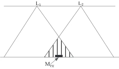
In this section, the indoor LED orientation and the trans-mitter system with which the different CEI protocols are investigated is examined. The scenario considered contains an overlapping region where signals from two LED light sources meet as illustrated in Fig. 2. Detecting overlap improves
positioning accuracy by creating more regions for localization [10]. In Fig. 2, three regions are decoded by the receiver instead of two.
L1
Mrx
[image:2.612.326.527.99.216.2]L2
Fig. 2. Illustration of overlapping region for CEI protocol investigation.
In Fig. 2, L1 and L2 are two LEDs in an enclosed space
transmitting their positional coordinates and Mrx is a mobile
receiver that is located in the overlapping region. For
sym-metry, L1 and L2 are identical LEDs and their properties are
given in Table I. Mrxis a photodetector based receiver in the
region under investigation and its properties are also given in Table I.
The transmitter is an infrared based LED system that en-capsulates an LED identity (LED-ID) in a frame, encodes the frame using one of the four encoding schemes and modulates the encoded data. The data is subsequently transmitted by the LED. The LED-ID carries the coordinates of the LEDs which is used to infer the receiver position.
TABLE I
PARAMETERS FORIR TRANSMITTER ANDRECEIVER
Parameters
Light emitting diode (LED)
semi-angle of half powerΦ1/2 ±35o peak wavelengthλp 860nm total radiant fluxφa 70mW rise and fall timetr,tf 12ns Photodetector (PD)
Directivity(θ) 45◦ Peak wavelengthλp 950nm Minimum irradianceE(emin) 0.12mW/m2 Detector physical area 1cm2 Refractive indexn 1.5 Field of Visionϕc 60◦ Microcontroller ATmega 328
Clock frequency 20MHz
III. ENCODING SCHEMES PERFORMANCE IN THE
OVERLAPPING REGION
using on-off-keying (OOK) due to its simplicity. The carrier frequency for CEI protocols is between 30 kHz and 50 kHz. The modulated signal is sent through a driver to the LEDs to
generate optical signals. Ifv(t)is the instantaneous value of a
waveform of the pulse with a period τ and signal levelsvmin
andvmax, then the average value of the waveform ofv(t)for
a single pulse is given by
vavg= 1 τ
Z τ
0
v(t)dt (1)
given the duration ofvmin andvmax astof f andton
respec-tively where ton+tof f =τ,
vavg= 1 τ
Z ton
0
vmaxdt+ Z tof f
0
vmindt
(2)
vavg= ton
τ vmax+ tof f
τ vmin (3)
The power consumption for transmission is proportional to this
quantity vavg. Each encoding scheme applied to the
overlap-ping region is therefore represented in subsequent sections as a function of the parameters in (3).
A. Pulse Distance Encoding
[image:3.612.340.546.59.126.2]In this encoding scheme, the delay (distance) between the pulses is used to map symbols as shown in Fig. 3a and Fig. 3b. The CEI protocols that makes use of PDE include the JVC, NEC and Sharp protocols [18]. This encoding offers the advantage of regulated power consumption as the duration with which the LED is on is constant irrespective of the bits considered. The delay between pulses used to decode bits makes this encoding scheme susceptible to error. Therefore, protocols which use this technique generally increase the amount of bits to be transmitted by injecting a level of redundancy to correct for errors. This phenomenon can be observed in the NEC and RCA protocols where address, inverse of address, data and inverse of data are transmitted in every frame.
t
ont
off(a) PDE for one
t
offt
on [image:3.612.336.532.291.366.2](b) PDE for zero
Fig. 3. General PDE representation of bits for CEI protocols
B. Pulse Width Modulation based encoding
Pulse width encoding varies the width of the pulse based on the data bit as shown in Fig. 4a and Fig. 4b. Unlike PDE, the variation in the pulse width of PWM makes the power consumption in PWM protocols higher. In order to compen-sate for this effect, CEI protocols that use this modulation techniques reduce the bits in transmission. Decoding reads the time between pulse rising and falling which makes PWM less susceptible to distortions by noise than PDE protocols. A popular CEI protocol which uses this encoding technique is the Sony SIRC [14].
t
ont
off(a) PWM for one
t
offt
on(b) PWM for zero
Fig. 4. General PWM representation of bits for CEI protocols
C. Biphase encoding
In this protocol, either a one is represented by a pulse then a delay and a zero by a delay then a pulse or vice versa as illustrated in Fig. 5a and Fig. 5b. This encoding protocol conserves power and also does not use long delays which could corrupt data. In addition the equal periods for ones and zeros could be used as an error detecting measure in decoding. Phillips RC5, RC6 and Nokia NRC are common CEI protocols that use this encoding technique [16].
t
off
t
on
(a) BPC for one
t
offt
on(b) BPC for zero
Fig. 5. General BPC representation of bits for CEI protocols
D. Pulse Position Modulation
Of the studied CEI protocols, only the Phillips RC-MM multimedia IR protocol uses pulse position modulation. Unlike other encoding protocols, the PPM CEI protocol uses a 4-PPM representation and therefore data is not just represented in 1s and 0s but in 00s, 01s, 10s, and 11s. In this encoding scheme, the position of the pulse determines the information it represents.
In order to evaluate the performance of each CEI protocol based encoding scheme in the overlapping region, their per-formances in the overlapping region are examined based on the probability of packet collision and positioning time. LED identity data from the two LEDs are encoded in each of these schemes. The encoded data is then arranged in packets based on the protocol(s) that makes use of the encoding scheme. These packets are subsequently modulated using OOK and transmitted through the LEDs. This results in a nonnegative
signal from each of the LEDs. Let x1(t) >0, represent the
instantaneous optical power from L1, the average transmitted
power of the optical signalPt1 is given in [11] by:
Pt1= lim τ→∞
1 2τ
Z τ
−τ
x1(t)dt (4)
In the same way, Pt2 is obtained from LED L2. Assuming a
channel modelH, in this region, the received power from the
PD receiver can be written as
[image:3.612.69.281.517.580.2]In MLEM, the packets are transmitted with the same carrier frequency, with the same wavelength, at the same time and in the same space (overlapping region). Transmitted packets are therefore subject to collision. Under this condition, with the similarity in channel model from the two transmitters, the probability of packet collision is 1. Pulse duration multiplexing (PDM), proposed in [10] is used to reduce the probability of collision. Theoretically, in a 2-LED overlapping region and for
a given duty cycleD, the probability of collisionPc is given
in [10] by Pc= 2D.
1) Simulation algorithm for determination of Probability of collision:
a. Given an n-bit LED-ID for LED L1, the data is encoded
using one of the four encoding schemes as explained in Section III.
b. The encoded data is encapsulated in a packet based on the protocol structure given in Fig 1.
c. The data carrying packet is modulated using OOK to a
carrier frequencyf.
d. Using PDM, the packets are multiplexed on
a low transmission duty cycle D, where
D=packettime/(packettime+delay)[10].
e. The process is repeated with LED data for L2.
f. The optical signals are transmitted from both LEDsNtx
times.
g. The signals are demodulated and decoded.
h. The number of non-collided packets, Nnc, and number
of collided packets, Nc are counted.
i. The probability of collision is given by Nc
Nnc+Nc which is
the same as Nc
Ntx.
j. The process is repeated varying 1/D (inverse of duty
cycle) from 2 to 50.
k. The process is repeated for other encoding schemes.
The evaluated comparison of probabilities of collision for the different encoding schemes are presented in Section IV-A. Positioning time is the time the receiver takes to identify its location. In non-overlapping regions, the receiver identi-fies position by interpreting the data in the packet received. However, in the overlapping region, the receiver is exposed to data from different sources and therefore after decoding the data from a particular source, the receiver does not state the decoded position as its location but rather, the receiver waits to gather positional information from all available transmitters in the overlapping region and then decodes this information. After arranging the encoded data in packet frames, if the time
to transmit the frame is tf, PDM embeds the frame in low
duty cycle pulses by transmitting the frame in time tf and
then having a longer delay or off time tof given by
tof =
(1−D)tf
D (6)
whereDis the duty cycle. The time to transmit a frame varies
depending on the protocol used for encoding and the number of ones and zeros in the LED identity data. For simulations, for a given encoding scheme, we use the protocol that has the shortest length of frame size and the frame time is taken as the average between the time to transmit a frame with a LED
identity data of all ones and that with a LED identity data of all zeros (considering even probability of ones and zeros).
In a region ofN LED transmitters, the positioning time, if
there is no possibility of collision, is given byN tf s. However
in the overlapping region, PDM guarantees a sequence of non-collided packets after a packet is lost in collision by spreading
data in the low duty cycle,D[17]. Therefore, the positioning
time in this region tp is given by
tp= N
D + 1
tf. (7)
Based on the system model shown in Fig. 2, N=2 and
thereforetp= D2 + 1tf.
After decoding all the positional information, the receiver predicts its location as the central point which is common to all the transmitters from which it received positional information. The performances of different encoding schemes based CEI
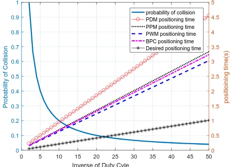
protocols in terms of positioning timetp and inverse of duty
cycle when simulated using MATLABr are illustrated in Fig.
[image:4.612.322.553.340.508.2]6. Measurements are taken in terms of the inverse of duty cycle because it is proportional to the positioning time as shown in Fig. 6.
0 5 10 15 20 25 30 35 40 45 50
Inverse of Duty Cyle
0 0.1 0.2 0.3 0.4 0.5 0.6 0.7 0.8 0.9 1
Probability of Collision
0 0.5 1 1.5 2 2.5 3 3.5 4 4.5 5
positioining time(s)
probability of collision PDM positioning time PPM positioning time PWM positioning time BPC positioning time Desired positioning time
Fig. 6. Performance of various encoding schemes with regards to positioning time and probability of collision.
E. Design of new IRP
The performances of the CEI protocols, as presented in the results from Fig. 6, do not suffice for real time tracking. Equa-tion (7) reveals that the posiEqua-tioning time is proporEqua-tional to the frame size of packets from the protocols. Therefore, in order to achieve the desired system, a protocol that allows shorter frame size is designed and its experimental performance is reported in Section IV-B. The protocol design rationale is given subsequently and the frame structure for this IRP is shown in Fig. 7.
1) Rationale behind the MLEM protocol frame design:
b. The protocol is to be embedded in a PDM scheme hence the lead outs and stop bit(s) become redundant and are therefore removed.
c. LEDs transmit their positional information, consequently, the data or command to be transmitted is the LED positional information thereby removing the need for a address, command combination.
d. 4 bits of information can represent up to 15 different light sources and in a standard room (with arbitrary dimension of 5 m by 5 m), the conventional practice is not to use up to 15 different light sources. Therefore the number of bits in the packets is reduced to 6 (two extra bits for wider spaces or future increase in luminaries in an enclosure). e. The start bits section of the packets are not removed as
this signifies the start of frame synchronization.
f. MLEM receivers are designed to operate in power saving modes. Therefore the pre-pulse and start combination is used to wake up the receiver. If the receiver is in its sleep mode and an accidental pulse, which does not match the pre-pulse and start combination, is detected by the receiver, such pulses are ignored.
Start bits Positional data bits
[image:5.612.321.548.62.269.2]Pre-pulse
Fig. 7. Designed infrared protocol for MLEM overlapping region
IV. RESULTS ANDDISCUSSIONS
In this section, results of the investigations of the various encoding scheme based CEI protocols in the overlapping region are presented in two forms. First are the results obtained
via simulation using the MATLABrcommunications toolbox.
To quantify this results, the probability of packet collision is presented and compared in theory and simulation. Then sec-ondly, simulation and experimental comparisons of positioning times for different protocols are given.
A. Simulation Results and discussions
By carrying out pulse duration multiplexing on the pulses, the probability of collision for the four encoding schemes are presented in Fig. 8a, Fig. 8b, Fig. 8c and Fig. 8d.
Irrespective of the encoding techniques used, the figures reveal that pulse duration multiplexing works for all situations in the overlapping region. However, compared to the other figures, Fig. 8d shows that 2-bit pulse position modulation (2PPM) has the lowest deviations from the PDM based theo-retical expectation. This is due to the presence of multiple bit symbol encoding in 2PPM compared to other techniques. Al-though, the different encoding schemes have different amounts of deviation, they all follow the theoretical prediction of the PDM scheme and therefore are all applicable in the MLEM overlapping region.
The positioning time of encoding schemes from different CEI protocols are shown in Fig. 6. In the figure, the NEC protocol and other PDE based protocols have the highest
0 10 20 30 40 50
Inverse of Duty Cycle
0 0.2 0.4 0.6 0.8 1
PDE probabiliy of collision
simulation theoretical
(a) pulse distance encoding
0 10 20 30 40 50 Inverse of Duty Cycle 0
0.2 0.4 0.6 0.8 1
PWM probabiliy of collision
simulation theoretical
(b) Pulse width modulation
0 10 20 30 40 50
Inverse of Duty Cycle
0 0.2 0.4 0.6 0.8 1
BPC probabiliy of collision
simulation theoretical
(c) biphase coding
0 10 20 30 40 50
Inverse of Duty Cycle
0 0.2 0.4 0.6 0.8 1
4-PPM probabiliy of collision
simulation theoretical
(d) pulse position modulation
Fig. 8. Probability of collision for different encoding schemes in overlap region
positioning times and at low duty cycles, it can be as high as
4.5s. Considering the low power consumption of PDE based
protocols, this protocol is suitable for systems where the object whose position is to be found (target object) is stationary. Examples of applicability of this includes the monitoring of equipment in an hospital, factory, laboratory or an educational institution. PPM, PWM and BPC have moderately better
positioning time where positioning is done once every 3 s.
These protocols show improvement in positioning time but do not suffice for positioning of mobile targets. Since the average
walking rate is approximately 1 m/s [19], for mobile targets,
indoor positioning is desired every second and therefore an
average positioning time of1s is derived for a desired protocol
that is suitable for the overlapping region of the MLEM.
B. Experimental Results and discussions
In this section, the outcomes of the experimental develop-ment of a CEI based protocol that suits the MLEM system is given.
Based on the performance of encoding schemes in the overlapping region (Section III), PWM is preferred as the encoding scheme for this protocol since it performs well for the overlapping region and is less susceptible to error in data transmission.
[image:5.612.86.246.321.361.2]0 5 10 15 20 25 30 35 40 45 50
Inverse of Duty Cycle
0 0.1 0.2 0.3 0.4 0.5 0.6 0.7 0.8 0.9 1
Probability of Collision
0 0.5 1 1.5 2 2.5 3 3.5 4 4.5 5
positioining time(s)
[image:6.612.63.290.53.223.2]probability of collision PDM positioning time PPM positioning time PWM positioning time BPC positioning time Desired positioning time Simulated designed system Experimental designed systen
Fig. 9. Performance comparison of the desired positioning time and the designed positioning time.
any region of two overlapping LED beams, a positioning time
of0.5s is achieved. This value surpasses the target for indoor
positioning of a moving person.
V. CONCLUSION
In this paper, the applicability of various encoding schemes from consumer electronics infrared protocols to the multiple LED estimation model (MLEM) for indoor positioning is investigated. The encoding schemes performed as expected in the overlapping region of MLEM but caused significant delays which increased the positioning time. A new protocol is there-fore developed that suits the conditions for MLEM design. This protocol is designed to accommodate for energy saving, work on low complexity microcontrollers and accommodate multiple light sources in an indoor location. The protocol is shown to perform better in the overlapping region and the
positioning time is reduced from4.5s to0.5s. In conclusion,
when applied to MLEM, it supports the development of a low cost, energy saving, and low positioning time IPS.
As future work, optimal pulse width for the protocol is designed by minimizing the pulse on and off duration while maintaining bit error rate and optical power constraint.
ACKNOWLEDGMENT
The authors would like to appreciate the support for this research work from the School of Engineering and Built Environment of Glasgow Caledonian University through the University sponsored research studentship.
REFERENCES
[1] M. A. Esmail and H. A. Fathallah, “Indoor visible light communication without line of sight: investigation and performance analysis,”Photonic Network Communications, vol. 30, no. 2, pp. 159–166, 2015.
[2] S.-H. Yang, H.-S. Kim, Y.-H. Son, and S.-K. Han, “Three-dimensional visible light indoor localization using AOA and RSS with multiple optical receivers,” Journal of Lightwave Technology, vol. 32, no. 14, pp. 2480–2485, 15 July 2014.
[3] J. Vongkulbhisal, B. Chantaramolee, Y. Zhao, and W. S. Mohammed, “A fingerprinting-based indoor localization system using intensity mod-ulation of light emitting diodes,” Microwave and Optical Technology Letters, vol. 54, no. 5, pp. 1218–1227, 2012.
[4] K. Dividis,Design and Prototyping of a Visible Light Indoor Positioning System. Citeseer, 2007.
[5] M. A. Elkarim, N. A. Mohammed, and M. H. Aly, “Exploring the per-formance of indoor localization systems based on VLC-RSSI, including the effect of NLOS components using two light-emitting diode lighting systems,” Optical Engineering, vol. 54, no. 10, pp. 105 110–105 110, 2015.
[6] C. Wang, L. Wang, X. Chi, S. Liu, W. Shi, and J. Deng, “The research of indoor positioning based on visible light communication,” China Communications, vol. 12, no. 8, pp. 85–92, 2015.
[7] H.-S. Kim, D.-R. Kim, S.-H. Yang, Y.-H. Son, and S.-K. Han, “An indoor visible light communication positioning system using a RF carrier allocation technique,”Journal of Lightwave Technology, vol. 31, no. 1, pp. 134–144, 1 January 2013.
[8] T. Huang, X. Gao, Y. Guo, S. Li, Q. Li, C. Li, H. Zhu, and Y. Wang, “Visible light indoor positioning fashioned with a single tilted optical receiver,” in14th International Conference on Optical Communications and Networks (ICOCN), Nanjing, 3-5 July 2015, pp. 1–4.
[9] K. Kaemarungsi and P. Krishnamurthy, “Modeling of indoor position-ing systems based on location fposition-ingerprintposition-ing,” inTwenty-third Annual Joint Conference of the IEEE Computer and Communications Societies (INFOCOM), vol. 2. IEEE, 7-11 March 2004, pp. 1012–1022. [10] O. Popoola, F. Ogunkoya, W. Popoola, R. Ramirez-Iniguez, and
S. Sinanovi´c, “Indoor localization based on multiple LEDs position estimation,” inSignal Processing Advances in Wireless Communications (SPAWC), 2016 IEEE 17th International Workshop on. IEEE, 2016, pp. 1–6.
[11] J. M. Kahn and J. R. Barry, “Wireless infrared communications,” Proceedings of the IEEE, vol. 85, no. 2, pp. 265–298, 1997.
[12] I. Millar, M. Beale, B. J. Donoghue, K. W. Lindstrom, and S. Williams, “The IrDA standards for high-speed infrared communications,” The Hewlett-Packard Journal, vol. 49, no. 1, pp. 10–26, 1998.
[13] Vishay Semiconductors, “Datasheet: TSFF5510 High Speed Infrared Emitting Diode, 870 nm, GaAlAs Double Hetero,” Retrieved Dec. 27, 2008 from http://www.vishay.com/docs/81835/tsff5510.pdf, Sep. 2008. [14] S. L. Augmented, “Application note: Implementation of transmitters and
receivers for infrared remote control protocols with mcus of the stm32f0 and stm32f3 series,” Retrieved October 12, 2016 from www.st.com, March 2016.
[15] A. O. Other, “Ir remote control codes,” Retrieved October 12, 2016 from http://read.pudn.com/downloads157/sourcecode/embed/701593/docs/IR, October 2001.
[16] K. Digital, “KD HDMS series IR protocol,” Retrieved October 12, 2016 from http://www.keydigital.com, October 2010.
[17] O. R. Popoola, W. O. Popoola, R. Ramirez-Iniguez, and S. Sinanovic, “Optimization of duty cycles for LED based indoor positioning system,” in2016 International Conference for Students on Applied Engineering (ICSAE), Oct 2016, pp. 368–372.
[18] Vishay Semiconductors, “Infrared Emitters,” Retrieved Jan. 25, 2011 from http://www.vishay.com/ir-emitting-diodes/.
![Fig. 3b. The CEI protocols that makes use of PDE includethe JVC, NEC and Sharp protocols [18]](https://thumb-us.123doks.com/thumbv2/123dok_us/1482614.100896/3.612.336.532.291.366/fig-cei-protocols-makes-pde-includethe-sharp-protocols.webp)