City, University of London Institutional Repository
Citation
:
Sun, Z. (2015). Micro Vortex Generators for Boundary Layer Control: Principles
and Applications. International Journal of Flow Control, 7(1-2), pp. 67-86. doi:
10.1260/1756-8250.7.1-2.67
This is the accepted version of the paper.
This version of the publication may differ from the final published
version.
Permanent repository link:
http://openaccess.city.ac.uk/14249/
Link to published version
:
http://dx.doi.org/10.1260/1756-8250.7.1-2.67
Copyright and reuse:
City Research Online aims to make research
outputs of City, University of London available to a wider audience.
Copyright and Moral Rights remain with the author(s) and/or copyright
holders. URLs from City Research Online may be freely distributed and
linked to.
1
Micro Vortex Generators for Boundary
Layer Control: Principles and Applications
Zhengzhong Sun
Department of Mechanical Engineering and Aeronautics, City University London
[Received date; Accepted date] – to be inserted later
Abstract
A review is given to the major developments in the boundary layer control by means of micro vortex generator (MVG). The appearance of MVG dates back to about three decades from the present review and this class of device rapidly spreads as an efficient and robust boundary layer control strategy for flows with separation in particular. Substantial successful applications of MVG have been achieved in subsonic flows and its application into supersonic flow is under progressive development, which requires the current status and capability of MVG to be reviewed. The fundamental aspects of MVG are first summarized, including its working principle and various geometries. Understanding of the fluid mechanics involved in the wake of a MVG device is of uppermost importance: the time-averaged and instantaneous wakes are discussed respectively. In the former, effects from the MVG geometry parameters are presented; while in the latter, focus is placed on the phenomenon associated with flow instability inside the wake. MVG’s applications in the subsonic regime are discussed, which covers the fundamental flow separation investigations and studies to tackle several practical problems. The ongoing studies in supersonic regime dealing with shock wave boundary layer interaction (SWBLI) induced separation are reviewed later, where the presentation is organized according to different types of SWBLI with emphasis on the interaction region.
1. INTRODUCTION
In order to achieve improved aerodynamic performance of a flying vehicle in aerospace industry, one may choose to design advanced aerodynamic components, resulting in the continuous effort in the optimization of aircraft design [1]. One may, alternatively, opt to flow control. There are active and passive control techniques, where pros and cons exist. The choice is really on a case-to-case basis.
2
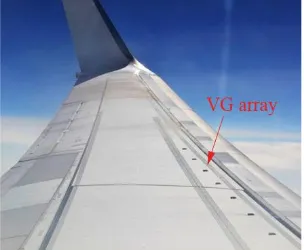
Figure 1. An array of vane-type VGs on the aircraft wing for shock buffeting control (photo taken on a B737-800 operated by Transavia flying from Barcelona to Amsterdam).
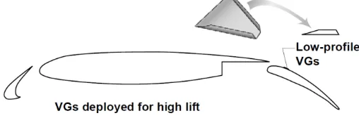
MVG was originally proposed in the late 1980s to increase the performance of aircraft high-lift device, such as flap [5]. It has been successfully used on several aircrafts since then and is still under development for further improvement [6]. Following the success of MVG in subsonic flow, it is recently introduced into the supersonic flow to tackle the problems caused by shock wave boundary layer interaction (SWBLI), especially flow separation [7].
The understanding of the flow mechanics involved in the MVG flow grows. At the beginning, due to the only availabilities of either single point (e,g, laser Doppler anemometry (LDA)) or two-dimensional velocity field measurement techniques (e.g. planar particle image velocimetry (PIV)) and the limited computational power, focus can only be placed on the time-averaged flow properties. Study of the instantaneous three-dimensional flow becomes possible with the invention of volumetric measurement technology, namely the tomographic PIV (Tomo-PIV) [8], and the realizations of computationally expensive high-order schemes [9] and the advanced simulation algorithms (e.g. large eddy simulation (LES), direct Navier-Stokes simulation).
The status of MVG studies and its applications requires this flow control technique to be reviewed, so that some established understandings scattered in the literature can be concluded and suggestions for further work can be made. The present paper will review and summarize the existing works on MVG and its applications into various low speed and high speed flows. The fundamentals of MVG, such as the working principle and its various geometries, will be first discussed. The wake flow properties produced by MVG are going to be elaborated in detail in both time-averaged and instantaneous viewpoints, after which applications of MVG in several flow problems will be summarized. Finally conclusions and suggestions for future studies are given.
2. MICRO VORTEX GENERATOR
2.1 Principles of Operation
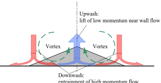
3 Downwash:
entrainment of high momentum flow Upwash:
lift of low momentum near wall flow
[image:4.595.152.425.70.211.2]Vortex Vortex
Figure 2. Front view of the micro ramp type MVG wake (free stream velocity is pointing into the plane).
2.2 MVG and Macro Vortex Generator (MaVG)
MVG is actually a recent development of MaVG concept, which was initiated by Taylor in the late 1940s [11]. MaVG usually consists of an array of small vertical plates or airfoils that emerge out of the boundary layer (see figure 3). An angle of attack was set relative to the local flow so that vortices could be produced in streamwise direction. After development for more than 50 years, MaVG obtains various geometries, such as vane and ramp. However, all the geometrically different devices share the similar principle of generating streamwise vortex.
Different from MaVG, MVG features a height smaller than the boundary layer thickness. It is thus also named sub-boundary layer vortex generator [12]. The MaVG and MVG are compared in figure 3. According to the definition by Holmes et al. [12], MVG has a height equivalent to the boundary layer momentum thickness (θ). But, in recent studies carried out in the supersonic regime, VG devices with height larger than the momentum thickness but smaller than the boundary layer thickness are also practically used in the class of MVG [4, 13].
Apart from the height difference, the MVG is devised to increase the momentum exchange between the outer and inner portions within the boundary layer, leading to a fuller velocity profile close to the surface, as well as a velocity deficit above (see figure 4). Difference can be found in the boundary layer profile controlled by MaVG, which is a result of momentum exchange between the region outside the boundary layer and the wall region.
Boundary layer edge MaVG
MVG Boundary layer
profile
[image:4.595.156.389.591.713.2]Figure 3 Size comparison of MaVG and MVG (adapted from Holmes et al. [12])
Figure 4 Boundary layer (BL) profiles controlled by MaVG (a) and MVG (b) (adapted from Holmes et al. [12]).
U/U∞
0.2 0.4 0.6 0.8 1.0
y
/δ
U/U∞
0.2 0.4 0.6 0.8 1.0
4 2.3 MVG geometry
2.3.1 Vane-type and ramp-type devices
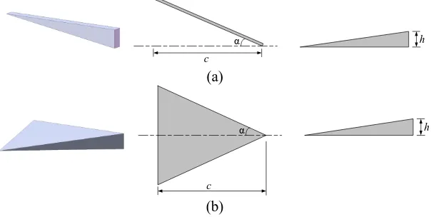
Various types of MVG have been investigated in literature, however, the two most studied ones in both low speed and high speed flows are the vane and ramp types (see figure 5). The vane type MVG, namely micro vane, is a piece of vertically installed plate with finite thickness. It has triangle [14], rectangle [15] or trapezoid [3] profiles. The most important geometrical parameters of micro vane are height (h), chord length (c) and angle of attack (α). Single micro vane produces one streamwise vortex. When it is used in array configurations, the micro vane may form co-rotating or counter-rotating (CR) configurations (see figure 6), whose resulted vortex systems are sketched in figure 7. According to recent works, both configurations have been used in low speed flows, while CR micro vane configuration are mostly applied for high speed applications.
The micro ramp is a ramp-shaped MVG device with slatted side edges (see figure 5(b)). Similarly, its geometry is defined by height h, chord length c and half span angle α (equivalent to the angle of attack for micro vane). As the micro ramp generates a pair of CR vortices, it is also the CR device. Although the micro ramp and CR micro vanes produce similar streamwise vortex structures, the CR micro vanes are able to generate stronger vortex in the immediate downstream [13].
α
c
h
(a)
α h
c
[image:5.595.147.449.302.454.2](b)
Figure 5 Micro vane (a) and micro ramp (b).
(a)
α
c
(b)
α
c
Figure 6 Micro vanes in co-rotating configuration (a) and counter-rotating configuration (b).
(a)
(b)
Figure 7 Schematic cross-sections of streamwise vortex systems behind co-rotating MVG array (a) and counter-rotating MVG array (b) (Kuethe 1972 [16]).
2.3.2 Development of MVG geometry
5
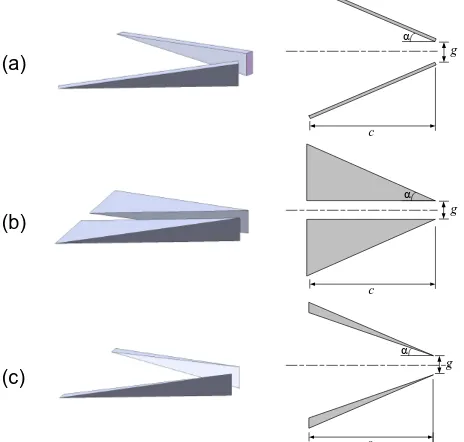
same principle, the split micro ramp [13] (figure 8(b)) is devised. Another novel type of device was proposed by mixing the features of micro ramp and micro vane. It thus has the name of ramped vane [17] (figure 8(c)) and is expected to endure higher aerodynamic loads, which is especially advantageous for supersonic applications.
(a)
α
c
g
(b)
c
g α
(c)
α
c
[image:6.595.181.413.126.347.2]g
Figure 8. Recent development of MVG geometry: (a) split micro vane (counter-rotating); (b) split micro ramp; (c) ramped vane.
3. WAKE PRODUCED BY MVG
Understanding the wake produced by MVG device is crucial for application. Fundamental investigations dedicated to the MVG wake were thus carried out. Their results on the time-averaged and instantaneous descriptions will be discussed in the present section. It should be noted that the coordinate system adopted here follows that used in most publications, namely the streamwise direction points to positive x, the wall normal direction points to positive y, the z-axis follows the spanwise direction forming the right-hand coordinate system, while the origin o locates at the point where the MVG trailing edge and wall connects.
3.1 Time-averaged wake
3.1.1 The velocity field
6
Figure 9 Cross-section of micro ramp wake at x/h=9 (Ma=2.0, δ=5.3 mm): (a) U/U∞, (b) V/U∞, (c) W/U∞. Vectors are projected in the contour of w (data acquired from the Tomo-PIV
[image:7.595.226.370.277.354.2]measurement of Sun et al. [20]).
Figure 10 Cross-section of micro vane wake at x/h=18.9 (Ma=3.0). The contour is colored by U/U∞ (adapted from Lee et al. [13]).
The wake velocity magnitude evolves when travelling downstream, which can be represented through a decay process. Babinsky et al. [4] and Nolan & Babinsky [21] measured the wake velocity decay resulted from micro ramps with different heights. Their studies discovered that the maximum deficit velocity (Umin within the wake region) follows similar trajectory when the wake is scaled with ramp
height. As a result, the ramp height is later commonly chosen as the length scaling parameter. The decay of wake velocity profile was also studied by Herges et al. [22] using Stereo-PIV. Sun et al. [23] paid special attention on the decay behavior till downstream position of x/h=30 in the center plane using planar PIV and formulated an exponential decay law for both the maximum deficit velocity (Umin) and peak
upwash velocity (Vmax). The recovery of deficit velocity as well as the elevation of the deficit region are
visualized in figure 11, whereas the decay of upwash velocity in center plane can be seen in figure 12. Moreover, the faster decay of the upwash velocity can be identified through cross-comparison of U and
V profiles.
[image:7.595.137.463.537.667.2]7
Figure 12 Profiles of time-averaged wall-normal velocity V in the center plane (data acquired from planar PIV experiment in [23]).
3.1.2 The streamwise vortex
[image:8.595.197.400.481.543.2]A conceptual model describing the organization of multiple streamwise vortex filaments was provided by Babinsky et al. [4], see figure 13. The primary vortex in the wake center dominates the vortical structures, while several other secondary filaments also co-exist. The secondary vortex originating from the junction of MVG trailing edge and wall has been identified in wind tunnel experiments through surface flow visualization [4, 22, 24, 25]. The visualization image of Lu et al. [24] is shown in figure 14, where the traces of secondary vortices vanish till about 5 ramp heights downstream, suggesting its relatively shorter life.
Figure 13. A conceptual model for the streamwise vortex system [4].
Figure 14. Surface flow visualization for the primary and secondary vortices [24].
3.1.3 Effects of geometry parameters on the MVG wake
The MVG wake and the embedded vortex are closely correlated with MVG geometry. In this section, effects from MVG height and device sweep angle (angle of attack) will be discussed.
Effect from MVG height
The micro ramp height effect has been studied by Lee et al. [13] using implicit large eddy simulation (ILES), where a baseline micro ramp with height h and one with half height (0.5h) were simulated. Their wakes, represented through velocity deficit, from both devices obtain similar width at the immediate downstream. However, a lower wake from the half-height ramp can be observed downstream at x/h=19 (see figure 15(a)(b)).
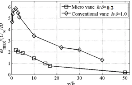
The height effect on vorticity intensity (ωmax) was studied by measuring single vane type VG of two
8
Figure 15 Wake cross-sections (x/h=0, 19) of micro ramp with different device heights (h, 0.5h) and sweep angles (α, 0.5α): (a) baseline micro ramp, (b) half-height micro ramp, (c) half
[image:9.595.184.410.340.486.2]sweep angle micro ramp (adapted from Lee et al. [13]).
Figure 16 Peak vorticity produced by vane-type vortex generators with different heights (adapted from Yao et al. [15]).
Figure 17 Peak vorticity produced by micro vane at three different angles of attack (adapted from Yao et al. 2009 [15]).
Effect of sweep angle
[image:9.595.187.400.523.644.2]9
The sweep angle effect on vortex intensity was also studied experimentally by installing a micro vane at three angles of attack [15]. The device at a larger angle of attack was revealed to generate stronger vorticity (see figure 17), but the difference shrinks at downstream locations. Eventually, all the vortices approach similar magnitude at about x/h=50.
3.2 Instantaneous flow organization
[image:10.595.163.430.257.424.2]The instantaneous flow exhibits structures strikingly different from the time-averaged one due to the flow instability of Kelvin-Helmholtz (K-H) type that takes place in the wake shear layer. The feature of this phenomenon is that the flow interface, namely the shear layer, rolls up and gives rise to intermittent vortices in cross flow plane [26]. One instantaneous flow snapshot and the time-averaged velocity field at the center plane are compared in figure 18, where the instantaneous MVG wake appears to be dominated by intermittent packets containing high/low velocity. This instability phenomenon was also qualitatively observed through laser smoke visualization (figure 19(a)) and nanoparticle-based planner laser-scattering (NPLS) visualization [27] where the imprints of roller structure are apparent [28] (figure 19(b)).
Figure 18 Instantaneous (a) and time-averaged (b) velocity field in the center plane of micro ramp wake measured by planar PIV, contour colored by velocity magnitude √𝑢2+ 𝑣2/𝑈∞2
(data acquired from Sun et al. [23]).
Figure 19 Visualization of the instantaneous micro ramp wake, (a) laser smoke visualization (Lu et al. [24]); (b) NPLS visualization (Wang et al. [28]).
[image:10.595.194.402.475.571.2]10
known that the streamwise vortices execute the flow control function, the reduced streamwise vortex intensity due to vortex interaction, in the transient sense, may affect the control result. However, in the time-averaged sense, the local adverse effect can be averaged out, as the K-H instability is not shown in the time-averaged flow field.
[image:11.595.105.491.132.277.2](a) (b) (c)
Figure 20 The vortical structure in the micro ramp wake: (a) the λ2 isosurface representing the
wake vortical structure from ILES simulation [29]; (b) the conditional averaged result of Tomo-PIV measurement [20]; (c) the λ2 isosurface representing the near wake vertical structure
from LES [31].
3. APPLICATIONS OF MVG
The growing understanding on the MVG wake accelerates MVG’s readiness for application. It has received established applications in subsonic flow, although its usage in supersonic flow is still under exploration. In the present section, the existing works will be discussed according to the speed regimes where the MVG is installed.
3.1 MVG in subsonic flow
3.1.1 Fundamental separation control
Fundamental studies have been carried out in the subsonic regime so that MVG’s capability in separation reduction can be evaluated. An exploratory experimental study performed by Rao &
Kariya [10] compared several types of MVG including the vane VG (h/δ≈1), semi-circular rod
(h/δ=0.35, 0.56) and concave slat (h/δ=0.56). These three types of devices were installed in both
co-rotating and counter-co-rotating configurations on a flat plate. The free stream velocity was 12 m/s and the boundary layer thickness was 22.9 mm. A nearly two-dimensional separation zone was established on the flat plate by adjusting the upper wall to a deflection angle of 20°, see figure 21(a) for the experimental setup. The flow field was evaluated by measuring the static pressure recovery across the separation zone as well as the total pressure loss for each type of device. The effects of device height, lateral spacing and angle of attack were tested. Finally, the results showed that MVG device has the potential of exceeding the performance of a conventional VG.
[image:11.595.132.474.584.725.2](a) (b)
Figure 21 Experimental setups for fundamental separation control by MVGs: (a) separation established by deflecting wind tunnel roof [10] (b) separation established on the backward
11
Fundamental studies on separation control were also carried out by Lin et al. [5,18]. The experiments were performed in a shear flow wind tunnel with free stream velocity of about 40 m/s and boundary layer thickness of about 32.5 mm. Instead of adjusting the wind tunnel top wall, the separation was established on a backward facing ramp, see figure 21(b). Three types of MVG with
various heights were installed: micro vane (h/δ=0.1, 0.2, 0.8), Wheeler doublet MVG (h/δ=0.1, 0.4)
and wishbone MVG (h/δ=0.1, 0.2, 0.4). Moreover, the effects of installation location and the device
lateral spacing were also investigated. The flow fields were eventually evaluated through the static pressure recovery along the wind tunnel centerline in combination with surface flow visualization. These experiments confirmed the effectiveness of MVG in separation reduction.
Ashill et al. [34] performed a separation control experiment where the separation was introduced by placing a bump in the test section. A boundary layer tunnel was used with free stream velocity of 40 m/s and a boundary layer thickness of 40 mm over the bump. Three types of MVGs including
the micro ramp, micro vane and split micro vane (with the gap g=1h) were tested. All the devices
had the same height of h=10 mm, resulting in a height ratio of h/δ=0.25. Different from the previous
two experiments, velocity was measured by LDA. A significant reduction in separation was achieved at the rear of the bump for all three devices, among which the split micro vane yielded the best outcome. Since then the split MVG device is adopted in later studies.
The above fundamental studies are summarized in table I. Note that the ratio h/δ is considered
[image:12.595.88.506.354.489.2]important for MVG study because it determines the relative size of MVG compared to the boundary layer. This ratio will also be stressed in the remainder of present review.
Table I. Studies of MVG for fundamental separation control.
U∞ (m/s) δ (mm) h/δ MVG
Rao & Kariya [10] 12 22.9 0.35, 0.56 0.56 1.0
semi-circular rod concave slat vane
Lin et al. [5] 40 32.5 0.1, 0.2, 0.8 micro vane
0.1, 0.4 Wheeler doublet
0.1, 0.2, 0.4 wishbone
Ashill et al. [34] 40 40 0.25 0.25 0.25
micro vane
split micro vane (g=1h) micro ramp
3.1.2 Applications in subsonic flow
The above fundamental studies verified MVG’s ability in separation reduction and led to applications of MVG into various engineering problems.
The most successful application of MVG in aeronautical industry is its alleviation of flow separation on the wing high-lift device, namely flap. This idea was initiated by Lin et al. [5]. Wind tunnel experiments were carried out and the measurements were made on a single-flap three-element airfoil model (see figure 22) at Ma=0.2. The MVGs tested were the triangle and trapezoid micro vane in both co-rotating and counter-rotating arrays. They were placed at three distances from the flap leading edge. The counter-rotating trapezoid vane was found to work most effectively when placed at 25% of the flap chord. An additional benefit of this installation position is that the MVG could be stowed under the main wing at cruise thus no additional drag will be introduced.
[image:12.595.169.423.640.724.2]12
Another study with similar objective was performed within the aircraft wing advanced technology operations program from Airbus [6], which includes a series of wind tunnel experiments and flight tests. The first wind tunnel experiment was carried out at Reynolds number of Re=2.2×10⁶. Two arrangements
of micro ramps were used and the wing lift coefficient increased by 2% for the flap deflection of 35°. Follow-up tests were performed at a higher Reynolds number of Re=6.6×10⁶, where flow separation was
significantly reduced by the MVGs at the same flap deflection angle of 35°. The MVGs were finally tested on an A340 flying testbed. It was demonstrated that MVGs can improve the low speed performance by reducing flow separation on the flap at full-aircraft scale.
Apart from the multi-element wing, MVG is also possible to be used in other places of an airframe. It was once installed on the V-22 aircraft for forward flight performance improvement, as flow separation over the midwing can be reduced [35].
3.2 MVG in supersonic flow
A unique flow feature in the supersonic flow is the shock wave, an aerodynamic interface bridging abrupt change of aerodynamic parameters, e.g. velocity, pressure. As soon as the shock wave encounters the boundary layer, comes the problem of shock wave boundary layer interaction (SWBLI), resulting in undesired problems, one of which is the boundary layer separation caused by the adverse pressure gradient associated with the shock wave. MVG was recently proposed to reduce shock induced separation. Although its early applications may date back to the late 1980s [36], the boom of studies on this topic occurs only very recently. The present review on MVG in supersonic flows will be organized according to the types of SBWLI, namely SWBLI produced by incident and normal shock wave respectively, and SWBLI on the compression ramp.
3.2.1 MVG and incident shock wave boundary layer interaction (ISWBLI).
[image:13.595.120.476.416.578.2]The ISWBLI has been discussed extensively by Dussauge et al. [37]. The incident oblique shock wave and the reflected shock wave are among the most significant flow structures in ISWBLI. An interaction region exists between the two shock feet. According to the occurrence of flow separation in the interaction region, ISWBLI can be classified into unseparated case and separated case. In the latter case, a reattachment shock wave forms immediately downstream of the separation bubble, see figure 23.
Figure 23 Schematic of the features of ISWBLI with separation (from Humble [38], based on Delery & Dussauge [39]).
The separated case of ISWBLI has been widely adopted to test the separation control effects of MVG. Babinsky et al. [4] performed an important experimental study, which later becomes the datum for subsequent numerical studies. The experiment was carried out in the supersonic wind tunnel operating at Ma=2.5. The boundary layer (δ≈6 mm) that develops over the wind tunnel floor was used to interact with the shock wave generated by a 7° wedge. Two geometrically similar micro ramps with heights of 3 mm and 6 mm (h/δ=0.5, 1.0) were installed and they were placed in both single and array arrangements respectively. The control effects were evaluated through oil flow visualization (see figure 24(a)) and surface static pressure variation across the interaction region. Velocity profiles were also studied at various streamwise and spanwise positions such that the three dimensional effects could be evaluated.
13
discussed in detail. The separation appears to be modulated in spanwise direction containing several individual "owl-face" separation bubbles, see figure 24(b). Another follow-up RANS study using immersed boundary treatment was carried out by Ghosh et al. [41], where the micro ramps were only in the single row configuration. The visualization of separation region qualitatively confirmed the previous experimental and numerical findings, see figure 24(c).
[image:14.595.97.510.140.256.2](a) (b) (c)
Figure 24 Flow visualizations in the interaction region: (a) oil flow visualization [4], (b) numerical surface streamlines [40], (c) near surface streamlines [41].
MVG effects on ISWBLI at a higher Mach number of Ma=3.0 was studied by Lee & Loth [13] using ILES, where the incident shock wave was generated by an 8° wedge and various types of MVG were considered. Investigation in the cross-flow planes allowed to quantify the decay of streamwise vortex intensity. Among all the devices studied, the peak vorticity produced by ramped vane produces the strongest intensity and the slowest decay, confirming the conclusion from experiment in subsonic flow [42]. The ramped vane also yields the best performance in terms of separation reduction.
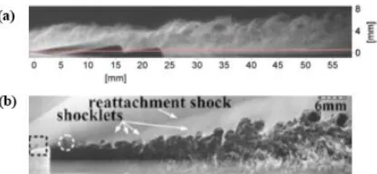
Another experimental study was carried out by Blinde et al. [30] at Ma=1.84. Stereo-PIV was used to study the flow resulted from micro ramps in single-row and staggered-row arrangements. The time-averaged velocity and velocity fluctuation were investigated in two planes parallel to the wall, see figure 25 for the time-averaged streamwise velocity distributions in the interaction region. According to the statistical analysis, probability of separation decreases in the position downstream of the micro ramp trailing edge, whereas increased probability was found in the rest regions. Relating the aforementioned studies, it could be concluded that separation in the interaction region is strongly modulated by the presence of MVG.
(a) (b) (c)
Figure 25 Streamwise velocity in the wall parallel plane showing effects of micro ramp arrays on ISWBLI, contour colored by U/U∞: (a) uncontrolled; (b) controlled by micro ramps in single
[image:14.595.214.382.570.689.2]row; (c) controlled by micro ramps in staggered rows [30].
Figure 26 NPLS visualizations of ISWBLI without control (a) and with micro ramp control (b).
14
distorted. At this point, one may wonder whether the distorted shock wave will place any additional effect on the interaction. The answer is not clear so far and further investigation is needed.
Optimization studies of micro ramp [44, 45] were carried out making use of ISWBLI. In the work of Anderson et al. [44], geometrical parameters including ramp height (h), chord length (c), device lateral spacing (s), the number of devices and the distance between ramp trailing edge and interaction region of SWBLI were considered as inputs. The pressure jump across the SWBLI (ΔP/P0) and boundary layer
shape factor (H) were chosen as response target and the response surface method (RSM) was used to determine the optimum. Results showed that H is not minimized in the design space as ΔP/P0 is
maximized. In the other optimization study by Hirt & Anderson [45], only (h, c, s) were chosen as inputs, while the boundary layer thickness (δ) and shape factor (H) were alternatively taken as response parameters. The RSM results revealed again that H is decreased at the cost of δ increase. Therefore, it can be concluded for MVG that optimization of one parameter is at the detriment of the other, and trade-off should be taken into consideration.
[image:15.595.182.415.579.722.2]The MVG studies in this category are summarized in table II.
Table II. Studies of MVG for ISWBLI control.
Ma δ (mm) h/δ Shock
generator MVG
Babinsky et al. [4] 2.5 6 0.5, 1.0 7° Micro ramp
Galbraith et al. [40] 2.5 7.5 0.4 7° Micro ramp
Ghosh et al. [41] 2.5 6 0.5, 1.0 7° Micro ramp
Lee & Loth [13] 3.0 -* 0.25, 0.5 0.5 0.5 0.5 0.5
8° Micro ramp
micro vane split micro ramp split micro vane ramped vane
Blinde et al. [30] 1.84 19 0.2 10° Micro ramp
Bo et al. [43] 2.7 6.3 0.48 10.5° Micro ramp
Anderson et al. [44] 2.0 11.4 0.26, 0.35, 0.44 10° Micro ramp, micro vane
Hirt & Anderson [45] 2.0 11.4 0.26, 0.35, 0.44 8.5° Micro ramp * Data not available.
4.2.2 MVG and normal shock wave boundary layer interaction (NSWBLI)
The NSWBLI usually occurs at the entrance of a supersonic diffuser and may also takes place on an airfoil at transonic speed (typically when Ma=0.7~0.9). For the latter case, it is known as shock-buffeting phenomenon [46]. A typical NSWBLI is represented schematically in figure 27. The normal shock wave features a λ-pattern shock system. The front leg is located at the beginning of the separation region and the rear leg is generated at the other end due to the boundary layer reattachment. A slip line forms at the intersection of the front and rear legs.
Figure 27. Schematic of the features of NSWBLI with flow separation [38].
15
The aerodynamic group of the University of Cambridge has carried out a series of studies on the NSWBLI control using MVG. Holden & Babinsky [14] performed experiments at Ma=1.5, where the normal shock wave was produced by adjusting the second throat downstream the test section. The turbulent boundary layer that naturally develops over the tunnel floor was used to interact with the normal shock wave and had a thickness of about 5.7 mm. The micro vane with height of 1.25 mm (h/δ=0.22) and the micro ramp with a height of 2 mm (h/δ=0.35) were tested. The normal shock wave was set at two positions, one at the MVG trailing edge and the other at 50 mm downstream the MVG trailing edge (40h for micro vane and 25h for micro ramp). Pressure measurement across the interaction region in combination with Schlieren photography and oil flow visualization were used to assess the effectiveness of MVGs. The micro vane was revealed to be more effective in separation reduction and induce the least wave drag among those tested.
Another study by Babinsky et al. [47] investigated the effect of micro vanes for a NSWBLI at Ma=1.3 and 1.5. In addition to shock induced separation, flow separation at a 6° expansion corner, replicating a supersonic diffuser, was studied. The normal shock wave was shifted at two locations by adjusting the supply and exhaust pressures. The micro vane was the same as that used in the previous study of Holden & Babinsky [14], thus the height ratio h/δ is 0.18 and 0.22 for Ma=1.3 case and Ma=1.5 case, respectively. The flow separation was also monitored by oil flow visualization.
In the follow-up study of Titchener & Babinsky [48], a shock holder was installed above the expansion corner in order to stabilize the normal shock wave. The Mach number was changed to Ma=1.4 and the shock wave was positioned exactly at the entrance of the expansion corner. A micro ramp and a ramped micro vane with the same height of h=2 mm (h/δ=0.38) were placed at three distances upstream the shock wave, namely xp/h=1.7, 31.5, 46.5. According to the pressure measurement and the oil flow visualization,
separation reduction was achieved at the cost of increased three-dimensionality. Using the same experimental setup, the ramped vane with h=2, 3, 4 mm (h/δ=0.38, 0.57, 0.76) and the split micro ramp with h=3, 4 mm (h/δ=0.57, 0.76) were investigated by Rybalko et al. [49]. The MVG arrays were placed at three distances from the diffuser entrance, namely 80, 133, 187 mm. An optimum was obtained for the largest ramped micro vane (h/δ=0.76) when placed at 133 mm, namely 33.25h, upstream of the interaction region. For this configuration, the smallest centerline incompressible boundary layer shape factor and least streamwise oscillations of normal shock wave were achieved.
[image:16.595.128.466.561.699.2]A supersonic diffuser geometry featuring a 5° expansion angle was simulated by Lee et al. [50] and Lee & Loth [17] using ILES. A normal shock wave was located immediately upstream of the diffuser entrance and the free stream Mach number was Ma=1.3. Three types of MVGs were simulated: micro ramp, split micro ramp and ramped vane. A wide range of parameters including device height, width and split distance were considered. In the former study, the performance of MVGs was evaluated in terms of separation reduction, downstream boundary layer shape factor, and total pressure recovery. The split micro ramp and ramped vane with largest split gap were able to reduce the separation area by as much as 27%, while the largest shape factor was produced by the ramped vane of smallest height. An example of the flow field downstream of the MVG is shown in figure 28. In the latter study [17], focus was placed on revealing the mean and instantaneous flow structure as well as the turbulence properties in the wake of the ramped vane.
16
Herges et al. [22] used Stereo-PIV to study the NSWBLI controlled by micro ramp, which was installed upstream of NSWBLI at Ma=1.3. Five spanwise planes were measured allowing the three dimensional effect to be studied. The field of view (FOV) has long extension in streamwise direction such that development of the velocity components and the turbulent quantities can be evaluated across the interaction region. The boundary layer shape factor (H) was studied. A smaller H was measured directly downstream of the micro ramp trailing edge, whereas a larger H was found away from the center plane. A further experimental investigation performed by Herges et al. [51] concerned the effect of MVGs on stabilizing shock oscillation. A similar experimental setup as the one in Herges et al. [22] was used, but a diffuser was added. The micro ramp and ramped vane were studied and shock waves were positioned immediately upstream and downstream of the diffuser entrance respectively. It was found that the MVGs were able to stabilize the shock unsteadiness when the shock wave was positioned in the diffuser. In contrast, the shock unsteadiness increased slightly when the shock wave was upstream diffuser entrance.
[image:17.595.183.422.605.742.2]The studies of MVG control for NSWBLI are summarized in table III.
Table III. Studies of MVG for NSWBLI control.
Ma δ (mm) h/δ MVG
Holden & Babinsky [14] 1.5 5.7 0.22 0.35
Micro ramp micro vane
Babinsky et al. [47] 1.3 1.5 6.9 5.7 0.18 0.22 Micro vane
Titchener & Babinsky [48] 1.4 5.3 0.38 0.38
Micro ramp ramped vane
Rybalko et al. [49] 1.4 5.3 0.38, 0.57, 0.76 0.57, 0.76
ramped vane, split micro ramp
Lee et al. [50] 1.3 - * 0.34
0.34
0.23, 0.34, 0.52
Micro ramp split micro ramp ramped vane
Lee & Loth [17] 1.3 - * 0.52 Ramped vane
Herges et al. [22] 1.3 4.77 0.36 Micro ramp
Herges et al. [51] 1.3 4.77 0.4 0.4, 0.6
Micro ramp ramped vane * Data not available.
4.2.3 MVG and the compression ramp interaction
The compression ramp interaction is the third type of SWBLI that is usually encountered in supersonic aerodynamics. A schematic overview of the compression ramp interaction is shown in figure 29. Due to the flow deflection and associated oblique shock waves, a strong adverse pressure gradient is generated at the corner region, where a separation bubble is resulted. In the case of figure 29, an oblique shock wave is formed at the beginning of the separation region and a reattachment shock wave is produced at the point where boundary layer reattaches.
17
Figure 30 Surface streamlines at the ramp corner [29].
In the work of Li & Liu [29] the effect of micro ramp on the flow separation at a 24° ramp was investigated using ILES. The reduction of flow separation was visualized right after the micro ramp trailing edge, which is similar to the observation in the previous studies on ISWBLI and NSWBLI control. The shock structure is also significantly altered due to the presence of micro ramp. The leading foot of the shock system in the uncontrolled case disappears in the center plane (figure 31). Distortion of shock wave similar as that occurred in figure 26 can be observed in figure 31(b), which leads to the investigation of the K-H vortex and shock interaction [53]. However, the study remains in the stage of qualitative observation and is not sufficient to give definitive suggestions.
[image:18.595.228.367.85.153.2](a) (b)
Figure 31. Numerical Schlieren at the center plane of compression ramp control: (a) no control; (b) micro ramp control [29].
The effect of the micro ramp on the flow unsteadiness in the separation region of a 24° compression ramp interaction was investigated experimentally by Verma et al. [52]. A close correlation between the pressure fluctuation and the device lateral spacing was detected. It was thus concluded that a smaller lateral spacing is beneficial in stabilizing the pressure oscillation in the separation region.
Studies of MVG control towards compression ramp interaction are summarized in table IV. It can be seen that studies in this class has not received as much attention as in the previous two types.
Table IV. Studies of MVG for compression ramp interaction control.
Ma δ (mm) h/δ Ramp angle MVG
Li & Liu [29] 2.5 -* 0.5 24o Micro ramp
Verma et al. [52]. 2 1.53, 3.85 0.26, 0.65 24o Micro ramp
* Data not available in the literature.
5 CONCLUSIONS
A review on the MVG wake flow and its impact to flow separation that occurs in different flow regimes has been presented. MVG’s potential in separation control has been initially demonstrated in low speed flows. Numerous scholars and engineers are being inspired to conduct follow-up studies in order to extend its applications. The recent research boom in MVG for SWBLI control has confirmed its control capability in high speed aerodynamics.
Considering the achievements out of the studies reviewed above, some general conclusions on boundary layer control by means of MVG can be made:
MVG wake
Co-rotating and counter-rotating configurations are adequately used in subsonic flow, but
the latter is preferred for high speed flow applications.
The counter-rotating MVG array has similar major flow structure when used in both
subsonic and supersonic flows.
The MVG wake is affected by the device geometry. The device height determines the wake
[image:18.595.106.494.289.378.2]18
The micro vane (counter-rotating) generally produces stronger vortex than the micro ramp
with the same height.
The primary vortex pair is affected by the device tailing edge gap, which reduces their mutual interaction.
Flow instability happens at the wake shear layer and gives rise to the K-H vortex.
MVG flow control
The MVG is able to reduce flow separation at both subsonic and supersonic flows.
The MVG controlled separation region exhibits three-dimensional effect and most
reduction happens in the locations right after the MVG trailing edge.
As can be seen in the above review, the engineering application of MVG to tackle the flow problems in supersonic flow is still in progress. Fundamental studies are needed to address the unsolved problems, such as the K-H vortex and shock interaction. Moreover, further studies on MVG installation in certain actual test rigs, such as model supersonic intake, may be beneficial to the realization of this flow control technology in high speed flows.
REFERENCE
[1] A. Abbas, J. de Vicente, E. Valero, Aerodynamic technologies to improve aircraft performance, Aerospace Science and Technology, 2013, 28, 100-132.
[2] M.L. Post, T. C. Corke, Separation Control on high angle of attack airfoil using plasma actuators, AIAA Journal, 2004, 42, 2177-2184.
[3] J.C. Lin, F.G. Howard, G.V. Selby, Turbulent flow separation control through passive techniques, AIAA paper, 1989, 976.
[4] H. Babinsky, Y. Li, C. W. Pitt Ford, Microramp control of supersonic oblique shock-wave/boundary-layer interactions, AIAA Journal, 2009, 47, 668-675.
[5] J.C. Lin, Control of turbulent boundary-layer separation using micro-vortex generators, AIAA paper, 1999, 3404.
[6] K. S. Bohannon, Passive flow control on civil aircraft flaps using sub-boundary layer vortex generators in the AWIATOR programme, AIAA Paper, 2006, 2858.
[7] H. Babinsky, N. Makinson, C. Morgan, Micro-vortex generator for supersonic engine inlets, AIAA paper, 2007, 521.
[8] G.E. Elsinga, F. Scarano, B. Wieneke, B.W. van Oudheusden, Tomographic particle image velocimetry, Experiments in Fluids, 2006, 41, 933-947.
[9] G.-S. Jiang, C.-W. Shu, Efficient Implementation of Weighted ENO Schemes, Journal of Computational Physics, 1996, 126, 202-228.
[10] D.M. Rao, T.T. Kariya, Boundary-layer submerged vortex generators for separation control – an exploratory study, AIAA paper, 1988, 3546.
[11] H.D. Taylor, The elimination of diffuser separation by vortex generators. United Aircraft Corporation Report, 1947, No.R-4012-3.
[12] A.E. Holmes, P. K. Hickey, W. R. Murphy, D. A. Hilton, The application of sub-boundary layer vortex generators to reduce canopy “Mach rumble” interior noise on the Gulfstream III, AIAA paper, 1987, 84.
[13] S. Lee, E. Loth, Supersonic boundary-layer interactions with various micro-vortex generator geometries, Aeronautical Journal, 2009, 113, 683-697.
[14] H. Holden, H. Babinsky, Effects of microvortex generators on the separated normal shock/boundary layer interactions, Journal of Aircraft, 2007, 44, 170-174.
[15] C.S. Yao, J.C. Lin, B.G. Allan, Flow-field measurement of embedded streamwise vortex generated from passive flow-control devices, International Journal of Flow Control, 2009, 1, 255-270.
[16] A. M. Kuethe, Effect of streamwise vortices on wake properties associated with sound generation, Journal of Aircraft, 1972, 9, 715–719.
[17] S. Lee, E. Loth, Impact of ramped vanes on normal shock boundary-layer interaction, AIAA Journal, 2012, 50, 2069-2079.
[18] J.C. Lin, G.V. Selby, F. G. Howard, Exploratory study of vortex-generating devices for turbulent flow separation control, AIAA paper, 1991, 42.
[19] Y. Yan, Q. Li, C. Liu, F. K. Lu, Numerical, experimental and theoretical studies on mechanism of K-H instability and ring generation behind supersonic MVG, AIAA paper, 2011, 676.
19
boundary layer, Physics of Fluids, 2012, 24, 055105.
[21] W. R. Nolan, H. Babinsky, Characterization of micro-vortex generators in supersonic flows, AIAA paper, 2011, 71.
[22] T. Herges, E. Kroeker, G. Elliott, C. Dutton, Microramp flow control of normal shock/boundary-layer interactions, AIAA Journal, 2010, 48, 2529-2542.
[23] Z. Sun, F. F. J. Schrijer, F. Scarano, B. W. van Oudheusden, Decay of the supersonic turbulent wakes from micro-ramps, Physics of Fluids, 2014, 26, 025115.
[24] F. K. Lu, A. J. Pierce, Y. Shih, Experimental study of near wake of micro vortex generators in supersonic flow, AIAA Paper, 2010, 4623.
[25] M. R. Saad, A. Che Idris, H. Zare-Behtash, K. Kontis, Micro-ramps in Mach 5 hypersonic flow, AIAA Paper, 2012, 676.
[26] J. W. Miles, On the generation of surface waves by shear flows Part 3. Kelvin-Helmholtz instability, Journal of Fluid Mechanics, 1959, 6, 583-598.
[27] Y. Zhao, S. Yi, L. Tian, Z. Chen, Supersonic flow imaging via nanoparticles, Science in China Series E: Technological Sciences, 2009, 52, 3640-3648.
[28] D. P. Wang, Z. X. Xia, Y. X. Zhao, Q. H. Wang, B. Liu, Vortical structures of supersonic flow over a delta-wing on a flat plate, Applied Physics Letters, 2013, 102, 061911.
[29] Q. Li, C. Liu, LES for supersonic ramp control flow using MVG at M=2.5 and Reθ=1440, AIAA Paper, 2010, 592.
[30] P. L. Blinde, R. A. Humble, B. W. van Oudheusden, F. Scarano, Effects of micro-ramps on a shock wave/turbulent boundary layer interaction, Shock Waves, 2009, 19, 507-520.
[31] D. Xue, Z. Chen, X. Jiang, B. Fan, Numerical investigations on the wake structures of micro-ramp and micro-vanes, Fluid Dynamics Research, 2014, 46, 015505.
[32] Q. Li, C. Liu, Implicit LES for supersonic microramp vortex generator: new discovery and new mechanisms, Modelling
and Simulation in Engineering, 2011, 2011, 1-15.
[33] Z. Sun, F. Scarano, B. W. van Oudheusden, F. F. J. Schrijer, Y. Yan, C. Liu, Numerical and experimental investigations of the supersonic microramp wake, AIAA Journal, 2014, 52, 1518-1527..
[34] P. R. Ashill, J. L. Fulker, K. C. Hackett, Research at DERA on sub boundary layer vortex generators, AIAA Paper, 2001, 887.
[35] T. C. Tai, Effect of midwing vortex generators on V-22 aircraft forward-flight aerodynamics, Journal of Aircraft, 2003, 40,
623–630.
[36] A. E. Holmes, P. K. Hickey, W. R. Murphy, D. A. Hilton, The application of sub-boundary layer vortex generators to reduce canopy “Mach rumble” interior noise on the Gulfstream III, AIAA Paper, 1987, 84.
[37] J. P. Dussauge, P. Dupont, J.-F. Debiève, Unsteadiness in shock wave boundary layer interactions with separation, Aerospace Science and Technology, 2006, 10, 85–91.
[38] R. A. Humble, Unsteady flow organization of a shock wave/boundary layer interaction, Doctoral thesis, Delft University of Technology, 2009.
[39] J. Delery, J. P. Dussauge, Some physical aspects of shock wave/boundary layer interactions, Shock waves, 2009, 19, 453-468.
[40] M. C. Galbraith, P. D. Orkwis, J. A. Benek, Multi-row micro-ramp actuators for shock wave boundary-layer interaction control, AIAA Paper, 2009, 321.
[41] S. Ghosh, J. I. Choi, J. Edwards, Numerical simulations of effects of micro vortex generators using immersed-boundary methods, AIAA Journal, 2010, 48, 92-103.
[42] P. R. Ashill, J. L. Fulker, K. C. Hackett, Studies of flows induced by sub boundary layer vortex generators (SBVGs), AIAA Paper, 2002, 968.
[43] W. Bo, L. Weidong, Z. Yuxin, F. Xiaoqiang, W. Chao, Experimental investigation of the micro-ramp based shock wave and turbulent boundary layer interaction control, Physics of Fluids, 2012, 24, 055110
[44] B. H. Anderson, H. Tinapple, L. Surber, Optimal control of shock wave turbulent boundary layer interactions using micro-array actuation, AIAA Paper, 2006, 3197.
[45] S. M. Hirt, B. H. Anderson, Experimental investigation of the application of microramp flow control to an oblique shock interaction, AIAA Paper, 2009, 919.
[46] P. Doerffer, C. Hirsch, J. P. Dussauge, H. Babinsky, G. N. Barakos, Unsteady effects of shock wave induced separation, Notes on numerical fluid mechanics and multidisciplinary design, vol. 114, Spinger, 2011.
[47] H. Babinsky, N. Makinson, C. Morgan, Micro-vortex generator for supersonic engine inlets, AIAA Paper, 2007, 521.
20
[49] M. Rybalko, H. Babinsky, E. Loth, Vortex generators for a normal shock/boundary layer interaction with a downstream diffuser, Journal of Propulsion Power, 2012, 28, 71-82.
[50] S. Lee, E. Loth & H. Babinsky, Normal shock boundary layer control with various vortex generator geometries, Computers & Fluids, 2011, 49, 233-246.
[51] T. Herges, G. Elliott, C. Dutton, Y. Lee, Micro-vortex generators and recirculating flow control of normal shock stability and position sensitivity, AIAA Paper, 2010, 1097.
[52] S. B. Verma, C. Manisankar, C. Raju, Control of shock unsteadiness in shock boundary-layer interaction on a compression corner using mechanical vortex generators, Shock waves, 2012, 22, 327-339.
![Figure 11 Profiles of time-averaged streamwise velocity U in the center plane (data acquired from planar PIV experiment in [23])](https://thumb-us.123doks.com/thumbv2/123dok_us/1494688.102152/7.595.107.498.68.244/figure-profiles-averaged-streamwise-velocity-center-acquired-experiment.webp)
![Figure 12 Profiles of time-averaged wall-normal velocity V in the center plane (data acquired from planar PIV experiment in [23])](https://thumb-us.123doks.com/thumbv2/123dok_us/1494688.102152/8.595.138.458.78.207/figure-profiles-averaged-normal-velocity-center-acquired-experiment.webp)
![Figure 21 Experimental setups for fundamental separation control by MVGs: (a) separation established by deflecting wind tunnel roof [10] (b) separation established on the backward facing ramp [5], the arrow points to the MVG device](https://thumb-us.123doks.com/thumbv2/123dok_us/1494688.102152/11.595.132.474.584.725/experimental-fundamental-separation-separation-established-deflecting-separation-established.webp)