Int. J. Electrochem. Sci., 9 (2014) 1250 - 1263
International Journal of
ELECTROCHEMICAL
SCIENCE
www.electrochemsci.org
Mathematical Modeling for Hard Trivalent Chromium Coatings
Thickness with Thin Zincates Interlayer on Pure Aluminum
E. Khodadad*, M.K. Lei**
Surface Engineering Laboratory, School of Materials Science and Engineering, Dalian University of Technology, Dalian 116024, China
*
E-mail: [email protected]
**E-mail: [email protected], [email protected]
Received: 31 October 2013 / Accepted: 11 December 2013 / Published: 5 January 2014
The trivalent chromium coatings were deposited on the pure aluminum substrate using a thin zincates interlayer. Zincates has considerably influenced in the formation of trivalent chromium deposit on the pure aluminum substrate. The plating temperatures, plating times and different pH ranges had significant effects on the thickness, uniformity and microstructure of trivalent chromium plating on the pure aluminum substrate. Results show the average thickness for homogenous chromium coating without pitting and microcracks was 35 μm at 30° C, pH = 2 and 40 min. The Vickers microhardness of the chromium coating was about HV 8.3 GPa under a load of 1 N. Experimental results were mathematically modeled with the response surface methodology (RSM) method by statistical software SPSS 19 and Design expert V6 to predicted coating thickness at different coating conditions.
Keywords: Aluminum substrate; trivalent chromium electroplating; zincates interlayer; mathematical modeling; RSM
1. INTRODUCTION
crack-free structure in trivalent chromium coating. Li et al. [9] expressed the current densities have important influence on the coating microstructure and composition. Glossy and crack-free deposited coatings which have good corrosion properties could be obtained under lower current densities. Successful electroplating of trivalent chromium may impart good mechanical properties such as hardness, wear, and abrasion resistance to aluminum substrates.
Electroplating of trivalent chromium directly on the aluminum substrate has not become commercially successful due to formation of the oxide films on the aluminum surface, which inhibit the direct electroplating of chromium coating on the pure aluminum [2]. Since aluminum exposed to air is always covered by a dense oxide coating, that must be removed before the parts can be plated, otherwise applied the chromium coating will be prevented. As regards aluminum has high potential reactivity with trivalent chromium solutions. Trivalent chromium bath are so acidic and chrome ions on the electromotive scale being very attracted to the pure aluminum substrate. It may cause prevent the successful deposition of the trivalent chromium coating on the pure aluminum substrate. Preparation of aluminum surface is quite specific, to protect re-oxidation of the aluminum surfaces during processing, zinc immersion deposits “zincates” are used for electroless nickel plating [14-17]. Previous research on electroless nickel coating on aluminum substrates showed that the zincates interlayer has considerably influence on the formation of deposits [3-5]. One of the steps proceeding for electroplating of trivalent chromium on the pure aluminum is the process of zincate immersion. The application of this process allows considerable improvement of the adhesion of the trivalent chromium to the aluminum substrate. The zincate protects aluminum against re-oxidation from atmospheric exposure. However zincates have very active redox reactions with trivalent chromium ions. Furthermore, the deoxidized parts must be protected during the transfer, to avoid re-oxidation of the highly active aluminum surfaces. In this study effect of the zincates interlayer on the direct deposition of trivalent chromium on pure aluminum substrates instead of other interlayer such as copper and nickel was studied. Commonly, chromium coatings are deposited from hazardous hexavalent chromium baths. In view of a very high toxicity of hexavalent chromium compounds, development of chromium electroplating processes on the base of trivalent chromium salts is a very important task of modern electroplating. Research on electroplating of trivalent chromium on pure aluminum substrate still devisable and was not adequate.
to obtain the regression equations. This model can be used to predict thickness of the trivalent chromium coatings with the same chemical composition and deposition conditions.
2. EXPERIMENTAL SECTION
Pure commercial aluminum plates with an area of 6 cm2 were used as substrates. Dimensionally stable titanium anodes (MMO) commercially obtained from Xinxiang Future hydrochemistry Co., China, with an area of 12 cm2 was used in order to reduce the anodic oxidation of Cr (III). Before plating, the substrates were polished and activated in HNO3 solution with a concentration of 50 vol.% for 15 s. Finally, the substrates were washed in alkaline solution and dried in the air atmosphere. Zincates were deposited from bath Sodium hydroxide (525 g/l), Zinc oxide (100 g/l), Ferric chloride (1 g/l) and Potassium sodium tartrate (10 g/l) at room temperature. Electroplating of trivalent chromium as deposited from baths composed of CrCl3·6H2O (200 g/l), HCOOH (32 ml/l), CH3COOH (10 ml/l), NH4Cl (30 g/l), KCl (60 g/l), H3BO3 (30 g/l). Trivalent chromium was deposited at a steady value of current density (30 A/dm2) and the pH range from (1.5-2.5) and the experiment for investigated better morphology and roughness and enough thickness were run in different temperatures from 25-35° C and time 20-60 min. Chromium electroplating was carried out in a usual thermo stated glass cell. In order to provide formation of stable Cr+3 ions complexes, a thermal treatment of the chromium bath was performed at a room temperature for 24 h. The current efficiency of chromium electroplating was calculated by comparing the weight gain of the cathode placed in the chromium plating bath [20]. The average values of current efficiency as well as chromium electroplating rate were calculated for each bath solution on different coating conditions.
The surface morphology and composition of the coating were investigated by a Carl Zeiss NTS GMBH–SUPRA55-32-76 scanning electron microscopy (FE-SEM). Cross-sectional composition of the coating was measured by an EPMA1600-SHIMADZU electron probe micro-analysis (EPMA). The coating hardness was characterized by Vickers microhardness (HV) using a HXD-1000TM tester under a 1 N load.
3. RESULTS AND DISCUSSION
3.1. Pretreatment of Al substrate and Zincates interlayer
Pure aluminum is quite active, redox reactions during zincates coating and thermodynamic reactions occur during trivalent chromium coating respectively. Zincates are an electrochemical exchange reaction between zinc complexes in solution and the aluminum substrate, depositing zinc crystallites at the expense of aluminum dissolution. The zincates protect the Al substrate, effectively providing a sound basis for subsequent deposition. During the zincates process the aluminum oxide film is first dissolved in zincates solution as follows Eq. 1 [3]:
Considering a specific system, the exchange process occurring during the zincate treatment of Al can be represented by the following Eq. 2 [1].
[image:4.596.53.557.538.655.2]3Na2(ZnOH)4 + 2Al (substrate) → 2NaAl(OH)4 + 4NaOH+3Zn (deposited) (2) Reaction in solution of Cr (III) before ions reach thermodynamic equilibrium state aqueous ammonia (alkaline) green color Cr (III) hydroxide is precipitated, Eq. 3 [21].
[Cr(H2O)6]3+(aq) + 3OH-(aq) → [Cr(OH)3(H2O)3](s) + 3H2O(l) (3) The hydroxide readily dissolves in acids to form salts, after ions reach thermodynamic
equilibrium, dark blue color chromium ions is precipitated, Eq. 4.
[Cr (OH)3(H2O)3](s) +3H3O+(aq) → [Cr(H2O)6]3+(aq) + 3H2O(l) (4) The redox equations reactions between reactions (2) and (3) will happen on the surface of the
zincates are, Eq. 5. Upon completion of reaction (5) the zincates will be removed, in this case the reduction of Cr+3 to Cr should start before Eq. 5 in the electrochemistry cell up to chromium coating will be deposited on the aluminum surface uniformly:
2Cr3+(aq) + Zn(s) → 2Cr2+(aq) + Zn2+ (aq) (5) If this process continued after short time zincate will be removed and pure Al will appear in
surface. Cr (III) has a redox reaction, with aluminum, Eq. 6 [22]:
Cr3+ + 2Al(s) → Al2O3(s) + 2Cr (6) The trivalent chromium baths was so acidic and Cr+3 ions were very positive to the aluminum
surface on the electromotive scale and aluminum oxide would forms and it lead to prevent sufficient adhesion of the chromium coating on the aluminum surface. Burzynska et al. [4] found after 4 min, the zincates thickness will be stable. For increasing the zincates layer, this process was executed four times.
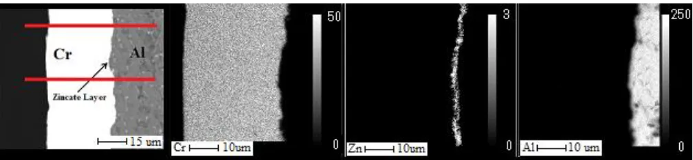
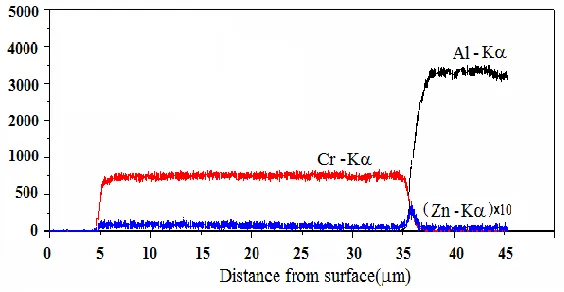
Figs. 1 and 2 show EPMA results of map and line scanning of element distribution to investigated cross-sectional examination of the trivalent chromium coating. Result shows the zincate was very thin. However it prevents the oxidation of the aluminum surface and provides the opportunity for the formation of chromium coating.
Figure 2. EPMA data: Line scanning of element distribution of the coating, at 30° C, plating time was 40 min, and pH=2.
3.2. Current efficiency
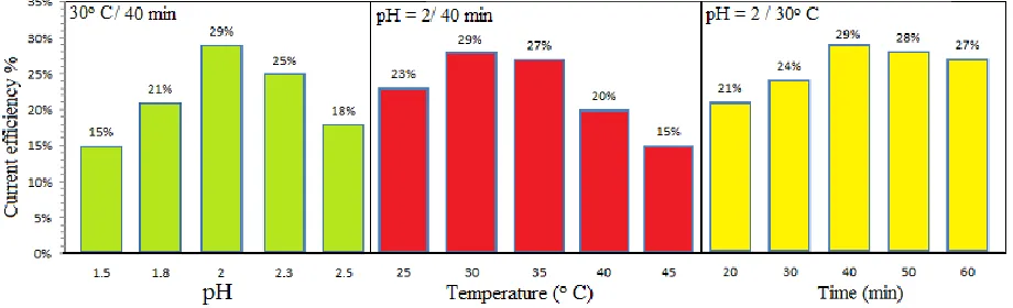
Fig. 3 shows effects of the different plating temperatures, plating times and pH ranging on current efficiency of chromium coating for different samples. The current efficiency of chromium electroplating was calculated by comparing the weight gain of the cathode placed in the coating process. Current efficiency (η %) was calculated as the ratio between the experimental and theoretical weight uptakes as described in a previous work [23]: η%= (ΔWmeas/ΔWtheo) ×100%. Previous research shows a current efficiency for trivalent chromium was near 30-35% [24-26]. The current efficiency of chromium electroplating for trivalent chromium bath was sufficiently greater than in the case of ordinary hexavalent chromium baths [25]. It should be stressed that the current efficiency of traditional chromium baths with simple solution without any special buffering does not exceed 10-20% [24]. However, in this study the current efficiency is near 29% at 30° C and 30 A/dm2
Figure 3. Dependencies of current efficiency upon the different pH ranges (1.5-2.5), plating temperatures (25-35° C) and plating times (20-60 min) for trivalent chromium coatings at 30 A/dm2.
3.3. Microstructure and morphology
[image:6.596.70.530.75.215.2][image:7.596.131.462.181.447.2]
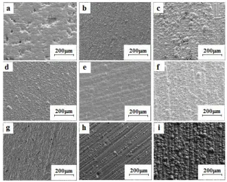
pure aluminum substrate was at 40 min and 30° C. Fig. 4 (g-i) shows the effect of different pH ranging on the morphology of the trivalent chromium coatings. These results expressed with increasing the pH up 2 the deposition rate and current efficiency was increased extremely, However when pH was more than 2 the coating roughness was increased and the microcracks and pitting was formed on the coatings surface.
Figure 4. Effects of different temperatures ranging (a-c)from 25 to 35° C at pH=2 with 40 min plating time. Effects of different plating times ranging (d-f) from 20-60 min at pH=2 and 30° C. Effect of different pH ranging (g-i) from 1.5-2.5 at 30° C and 40 min on the deposition of trivalent chromium coating at 30A/dm2.
3.4. Mathematical Modeling for Trivalent Chromium Thickness
Table 1. Primary coatings input variables for experimental design levels for mathematical modeling of trivalent chromium coatings, at 30 A/dm2.
Variables -1 0 1
Temperature (o C) 25 30 35
Time (min) 20 40 60
pH 1.5 2 2.5
the experimental data to obtain the regression equations. The sequential F-test, lack-of-fit test and other adequacy measures were used in selecting the best models.
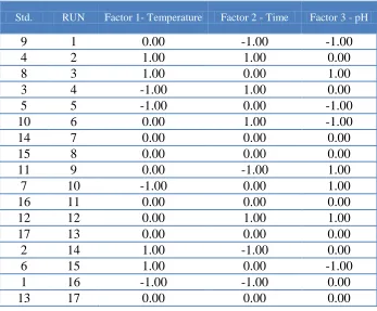
[image:8.596.125.474.273.562.2]The design matrix and the average measured responses were calculated by statistical software. Estimation of a full quadratic model with the general description: N = 2 k − p+2k + Co, [32] where (N) is the number of experiments, (k) is the number of independent variables, (p) the fractionalization number and Co is the number of central points, required for curvature estimation. To investigate the primary parameters the initial experimental set up was prepared. Table 2 shows the initial parameters for investigating thickness of trivalent chromium coatings in this research.
Table 2. Initial coatings parameters input for experimental design levels for mathematical modeling of trivalent chromium coatings, at 30 A/dm2.
Std. RUN Factor 1- Temperature Factor 2 - Time Factor 3 - pH
9 1 0.00 -1.00 -1.00
4 2 1.00 1.00 0.00
8 3 1.00 0.00 1.00
3 4 -1.00 1.00 0.00
5 5 -1.00 0.00 -1.00
10 6 0.00 1.00 -1.00
14 7 0.00 0.00 0.00
15 8 0.00 0.00 0.00
11 9 0.00 -1.00 1.00
7 10 -1.00 0.00 1.00
16 11 0.00 0.00 0.00
12 12 0.00 1.00 1.00
17 13 0.00 0.00 0.00
2 14 1.00 -1.00 0.00
6 15 1.00 0.00 -1.00
1 16 -1.00 -1.00 0.00
13 17 0.00 0.00 0.00
[image:8.596.125.472.275.562.2]
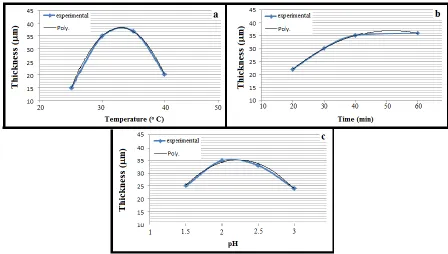
was constant and increased very slightly; it may because of the formation of Cr+3 hydroxo-complexes near the anode during chromium deposition. Fig. 5 (c) shows the effects of the pH on the thickness of the trivalent chromium coating.
[image:9.596.73.521.334.588.2]Commonly in the normal bath containing formic acid, the drop of hydrogen gas current efficiency from 100% at -1.06 V versus SHE corresponds to the beginning of trivalent chromium ion reduction. Hydrogen evolution is the most dominant reaction during the trivalent chromium plating process [20]. Most of the electricity passed through the cell was consumed by the hydrogen evolution reaction, which increases the pH of the solution at the cathode surface especially at high cathode over potentials. The sequence of electroplating of chromium involved the reduction of a complex Cr3+ ion to a complex Cr2+ ion and then from the complex Cr2+ ion to Cr(s). The rate of electroplating reaction was controlled by the diffusion of the complex Cr3+ ion to the cathode surface [20]. When the pH is higher than 2, the rate of evaluation of the hydrogen also is higher and it had worst effect on the surface roughness and leads to the lower rate of the trivalent chromium ions reduction to the chromium coating.
Figure 5. Effects of the different plating temperatures (a) at (pH = 2, plating time = 40 min), plating times (b) at (Temperature = 30°C, pH=2) and different pH (c) ranging at (Temperature =30°C, plating time = 40 min) on the coating thickness of chromium coating for different samples at 30A/dm2.
(7)
Where bo is constant of the regression equation, coefficients b1, b2, b3, are linear terms, the
coefficients b11, b22, b33, are quadratic terms and the coefficients b12, b13 and b23 are interaction terms. Analyzing was measured responses by the design expert software. The fit summary output indicates that the RSM model is statistically significant for the coating thickness ‘the second response’ therefore it will be used for further analysis. While for the other responses the quadratic models are statistical recommended for further analysis. The final mathematical models in terms of actual factors as determined by statistic software SPSS 19 are shown in Eq.8 for the prediction of coating thickness (YThickness) for trivalent chromium coatings.
Y Thickness (µm) = -0.12117 × (Tc) 2
-6.12656E-003 × (tc) 2
-4.99750 × (pH)2+0.000001×(Tc×tc) +0.10050×(Tc×pH) +0.025000× (tc×pH) +7.78437×(Tc) +0.56237×(tc)+19.83375×(pH) -130.34375
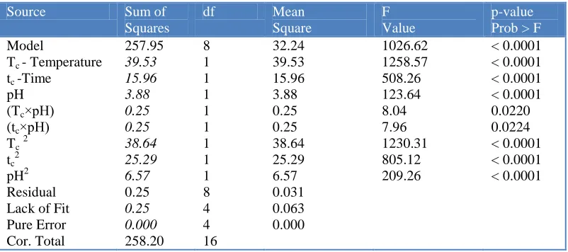
[image:10.596.99.500.559.737.2]The test for significance of the regression models and the lack-of-fit test were performed using the same statistical package. By selecting the step-wise regression method, which eliminates the insignificant model terms automatically, the resulting ANOVA Tables 3 for the reduced quadratic models summarize the analysis of variance of each response and show the significant model terms. The table show the adequacy measures Squared=0.9990, Adj Squared=0.9981, Pred R-Squared=0.9903, Adeq Precision=100.628and F-value of 1026.62 implies the model is significant. Values of "Prob > F" less than 0.0500 indicate model terms are also significant. In this research "Prob > F" Tc, tc and pH values are significant in model terms. Values greater than 0.1000 indicate the model terms are not significant. The entire R-Squared measures are close to 1, which is in reasonable agreement and indicate adequate models. The adequate precision ratio above 4 indicates adequate model discrimination in this experiment it 100.628. The analysis of variance indicates that for the coating thickness (YThickness), the main effect of the temperature (Tc), plating times (tc), the two level interaction of coating conditions (Tc×tc), (Tc×pH), (tc×pH) are the most significant associated terms model for (YThickness).
Table 3. ANOVA for response surface quadratic model for trivalent chromium coating at 30 A/dm2.
Source Sum of Squares
df Mean Square
F Value
p-value Prob > F
Model
Tc - Temperature
tc -Time
pH (Tc×pH)
(tc×pH)
Tc2
tc2
pH2 Residual Lack of Fit Pure Error Cor. Total 257.95 39.53 15.96 3.88 0.25 0.25 38.64 25.29 6.57 0.25 0.25 0.000 258.20 8 1 1 1 1 1 1 1 1 8 4 4 16 32.24 39.53 15.96 3.88 0.25 0.25 38.64 25.29 6.57 0.031 0.063 0.000 1026.62 1258.57 508.26 123.64 8.04 7.96 1230.31 805.12 209.26 < 0.0001 < 0.0001 < 0.0001 < 0.0001 0.0220 0.0224 < 0.0001 < 0.0001 < 0.0001
*Significant Model, R-Squared=0.9990, Adj R-Squared=0.9981, Pred R-Squared=0.9903, Adeq Precision=100.628 j i i ij i i ii i i i
Th ickn ess b bx b x b x x
[image:11.596.168.437.156.382.2]
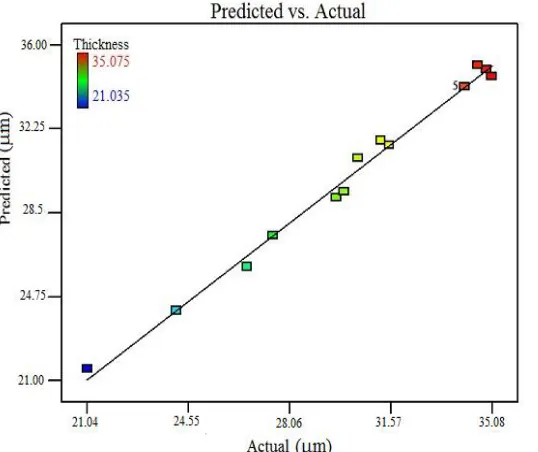
Fig.6 indicated that the developed models are adequate because the residuals in prediction of each response are optimal, since the residuals tend to be close to the diagonal line. The present model analysis indicated that there is a polynomial relationship between the effects of the three parameters.
Figure 6. Scatter diagram for (Predicted vs. Actual) of the developed mathematics model for trivalent chromium coating thickness at 30 A/dm2.
Fig.7 (a,b) shows the effect of (Tc and tc) on the coating thickness and the contour graph of the (Tc and tc) effects on the coating thickness at 30 A/dm2 and pH = 2. Results show that the plating times and plating temperatures are significantly affecting on the coating thickness.
[image:11.596.50.537.511.705.2][image:12.596.151.444.232.406.2]
To better understanding of the mathematics model, the chromium coatings was prepared at 32° C, pH = 2 for 45 min to investigated coating properties. Fig. 8 shows thickness of this trivalent chromium coating. The average of experimental coating thickness was 35.26 µm and the mathematics model predicted this value 35.573 µm. SEM observation shows the adhesion of the coatings were satisfactory and the model which is in reasonable agreement to experimental data. Fig. 10 shows x-ray diffraction spectra of chromium layers prepared in trivalent chromium baths. Result shows the chromium coating has the amorphous type microstructure. The Vickers microhardness at 1 N load was measured HV 8.3 GPa.
Figure 8. Cross sectional view of the chromium coatings was prepared at 32° C, pH = 2 for 45 min to investigated mathematics model vs. experimental data.
4. CONCLUSIONS
toxicity of hexavalent chromium compounds, development of chromium electroplating processes on the base of trivalent chromium salts is a very important task of modern electroplating. Recently in Europe use the maximum concentration in liquid effluent should be less than ~0.1 µgL-1
. In this research experimental results will be mathematically modeled by Response Surface Methodology (RSM) with statistical mathematics modeling to predict the properties of hard chromium coatings. The linear and polynomials will be fitted to the experimental data to obtain the regression equations. Box– Behnken design can be employed to develop mathematical models. Response surface methodology (RSM) was designed to predict the thickness of the trivalent chromium coating. The desired high quality thick trivalent chromium coatings can be achieved by choosing the working condition used in this developed models.
ACKNOWLEDGEMENT
We acknowledge contributory discussions and technical assistant of W. Zhang, C. J. Sun, and S. Tong in this research. One author (Erfan Khodadad) gratefully acknowledges Chinese Scholarship Council (CSC), China, for the financial support.
References
1. E. Stoyanova and D. Stoychev, J. App. Electrochem., 27 (1997) 685.
2. W. Deqing, S. Ziyuan , and K. Tangshan, Surf. Coat. Technol., 191 (2005) 324. 3. E. Khan, C. Oduoza , and T. Pearson, J. App. Electrochem., 37 (2007) 1375. 4. L. Burzyńska, E. Rudnik , and K. Ćwięka, Archives Met. Mat., 54 (2009) 845. 5. M. Hino, K. Murakami, Y. Mitooka et al., Mat.Trans., 50 (2009) 2235.
6. K. Murakami, M. Hino, R. Furukawa et al., Mat.Trans., 51 (2010) 78. 7. W. h. Hui, J. j. Liu, Y. s. Chaug et al., Wear, 192 (1996) 165.
8. S. Kwon, M. Kim, S. Park et al., Surf. Coat. Technol., 183 (2004) 151. 9. B. Li, A. Lin , and F. Gan, Surf. Coat. Technol., 201 (2006) 2578. 10.Z. Zeng, A. Liang , and J. Zhang, Electrochim. acta., 53 (2008) 7344.
11.F. Danilov, V. Protsenko, T. Butyrina et al., Prot. Met. Phys. Chem. Surf., 47 (2011) 598. 12.R. Giovanardi and G. Orlando, Surf. Coat. Technol., 205 (2011) 3947.
13.F. Danilov, V. Protsenko, V. Gordiienko et al., App. Surf. Sci., 257 (2011) 8048. 14.A. H. Du Rose Chromium Nickel Plating: Google Patents (1971).
15.B. S. Xu, H. D. Wang, S. Y. Dong et al., Electrochem. Communications, 7 (2005) 572. 16.C. A. Huang, U. W. Lieu , and C. H. Chuang, Surf. Coat. Technol., 203 (2009) 2921. 17.P. Najafi Sayar and M. Bahrololoom, Tran. Instit. Met. Finish., 87 (2009) 246. 18.H. El Kadi, Com. Struc., 73 (2006) 1.
19.N. Morawej, D. G. Ivey , and S. Akhlaghi Improvements in the Process for Electrodeposition of Au-Sn Alloys. CS MANTECH Conference, Vancouver, British Columbia, Canada, April, (2006) 24.
20.Y. B. Song and D. T. Chin, Electrochim. acta., 48 (2002) 349.
21.E. Crabb, E. Moore , and L. Smart Concepts in Transition Metal Chemistry: Royal Society of Chemistry,(2009).
22.S. S. Kazhikenova, O. Nurkenov , and B. Satbaev, Ref. Indust.l Ceram., 52 (2011) 55. 23.C. Fontanesi, R. Giovanardi, M. Cannio et al., J. App. Electrochem., 38 (2008) 425. 24.J. Golby and J. Dennis, Surf. Technol., 12 (1981) 141.
26.V. Protsenko, V. Gordiienko, F. Danilov et al., J. Chem., 8 (2011) 1925. 27.V. Gordiienko, F. Danilov , and S. Kwon, Met. Finishing, 109 (2011) 33. 28.F. Danilov and V. Protsenko, Prot. Met., 37 (2001) 223.
29.M. Svensson and G. Holmborn Thickness Distribution Control of Electrodeposited Nickel Pads for Microelectronic Interconnections. Proc. AESF annual tech. conf. 82, (1995) 145.
30.K. Popov, S. Zecevic, S. Pesic et al., J. Serbian Chem. Soc., 61 (1996) 1225. 31.S. C. Ferreira, R. Bruns, H. Ferreira et al., Anal. Chim. Acta., 597 (2007) 179. 32.C. Madeira, S. Ribeiro, M. Turk et al., Biotechnol. lett., 32 (2010) 1393.
33.M. Paunovic and M. Schlesinger, Fundamentals of Electrochemical Deposition, Second Edition (2005).