Int. J. Electrochem. Sci., 11 (2016) 1395 - 1415
International Journal of
ELECTROCHEMICAL
SCIENCE
www.electrochemsci.org
The Effects of Prior-Deformation on Anodic Dissolution
Kinetics and Pitting Behavior of 316L Stainless Steel
Junjie Chen1, Qian Xiao1, Zhanpeng Lu1,2,*, Xiangkun Ru1, Guangdong Han1, Yongwu Tian1, Tetsuo Shoji3
1
Institute of Materials Science, School of Materials Science and Engineering, Shanghai University, Shanghai 200072, China
2
State Key Laboratory of Advanced Special Steels, Shanghai University, Shanghai 200072, China 3
New Industry Creation Hatchery Center, Tohoku University, Sendai 980-8579, Japan *
E-mail: [email protected]
Received: 14 October 2015 / Accepted: 17 November 2015 / Published: 1 January 2016
The effects of prior-deformation produced by cold roll on anodic dissolution and pitting behaviors of 316L stainless steel (SS) in sulfuric acid solutions with chlorides are investigated by electrochemical mesurements, materials microstructure anlysis and surface analysis techniques. Cold roll decreased the Σ3 CSL grain boundaries proportion and increased the local misorientation in 316L SS. The effect of cold roll was more significant in sulfuric acid solution with chlorides than in chloride-free solution. Chlorides and cold roll had a synergistic effect on accelerating anodic dissolution. The current densities under potentiostatic polarization, pits numbers and open pit diameters increased with increasing applied potentials for both solution annealed 316L SS and cold rolled 316L SS. Cold roll increased the number of pits and decreased the pit size at a certain applied potential.
Keywords: stainless steel; prior-deformation; electrochemical behavior; pitting corrosion; anodic dissolution; chloride ion.
1. INTRODUCTION
deformation bands and even the phase transformation [1-3]. These changes of material and mechanical properties would affect the corrosion and cracking resistance of austenitic stainless steels in environments. The presence of certain amount of chromium in austenitic stainless steel results in the passive state with high stability and good corrosion resistance. [4, 5]. Pitting is one of the severe attacks of austenitic stainless steels in natural or industrial environments especially in chloride-bearing solutions [6].
Several studies investigated the influence of cold work on corrosion resistance of austenitic stainless steels in chloride solutions [1, 7-22]. The effects of plastic deformation on pitting potential have been found to be highly dependent on the test methods and environments [1, 7-16]. It has shown that the pitting potential of austenitic stainless steels decreases by cold rolling [7-12]. However, it has also reported that the pitting potential of work-hardened stainless steel increases [13, 14]. The chloride concentration and the degree of cold work may influence the change of pitting potential of stainless steels. Barbucci et al. [1] found that for 304 SS in sulfate solutions with chlorides, the susceptibility to pitting attack increased with increasing the work-harden degree for chloride concentrations higher than 5×10³
ppm. However, the tendency seemed to be the contrary for chloride concentrations lower than 5×10³
ppm. Haanappel et al. [15] reported that the pitting potential for 304 SS in NaCl solution decreased with a low deformation but increased with a high deformation. Kumar et al. [16] reported similar results. Xu et al. [17-19] reported that the deformation-induced martensite transformation reduced the pitting susceptibility of 304 stainless. Mudali et al. [20] investigated the effect of cold rolling degree of 0-50% on the localized corrosion resistance of 316L, 316LN and 316L HN, and found that the pitting potential was the highest with a 20% cold roll. Yu et al. [21, 22] studied the influence of different rolling processes on the corrosion resistance of 316L SS. The cross-shear rolled 316L SS showed better corrosion resistance than the synchronous rolled 316L SS in sulfuric solutions with chlorides which due to the numbers of mechanical twins induced by cross-shear rolling.
According to Nava and Debbouz [23, 24], the thickness and composition of passive films of 302 stainless steel varied with the types of stresses such as compressive or tensile stresses. Both the thickness and the Cr/Fe ratio of the passive film on a 304 stainless steel increased after the cold roll procedure [13]. Some literatures reported that cold work increased or left unchanged the pit numbers and decreased pit size [25-27]. Štefec et al. [28] found that the pit numbers usually increased with increasing pre-deformation degree and the rate of pit growth increased even after a small deformation, but higher degree of deformation had little additional effect. Nakhaie and Moayed pointed out the necessity on the influence of cold work on localized corrosion of stainless steels [29].
Plastic deformation accompanies crack growth and plays a key role in many mechanisms for stress corrosion cracking [30]. The interaction between crack tip deformation and crack tip environments is one of the key issues in environmentally assisted cracking such as stress corrosion cracking and corrosion fatigue [31-34]. Cold work could markedly accelerate the crack growth of austenitic stainless steels in high temperature water environments [35-38]. Enrichment of chloride ions and hydrogen ions at the stress corrosion crack tip would result in the increasing of local chloride concentration and the decreasing of pH and therefore accelerate the localized corrosion [39].
with chlorides were used to simulated environments related to localized corrosion or environmentally assisted cracking. It is necessary to evaluate the effects of cold work on the electrochemical kinetics, the localized corrosion behavior, and the interaction with the environmental factors.
In the present work, the effects of prior-deformation produced by cold roll on electrochemical and pitting behaviors of 316L SS are investigated. The combined effects of main alloy elements and microstructure, cold roll and chloride concentration on anodic dissolution and pitting corrosion are analyzed.
2. EXPERIMENTAL
316L stainless steel was solution annealed at 1100 °C for 30 min and water quenched. Before cold roll, the surface oxide film formed during annealing was removed. The solution annealed 316L was cold rolled one-directionally by multiple passes (8 passes) rolling to a total reduction of thickness of 20%. Solution annealed 316L is called as 316L-SA and the 20% cold rolled 316L SS as 316L-CR. 99.9% Cr, 99.9% Ni and 99.5% Fe were also used to investigate the effect of alloy elements on anodic dissolution and passivation. The chemical compositions of 316L are shown in Table 1.
Table 1. Chemical compositions (wt.%) of 316L SS used in the experiments.
C Si Mn P S Ni Cr Mo Fe
0.023 0.16 1.11 0.015 0.002 12.27 17.00 2.32 Bal.
region where cold wok show a significant effect, rather than the values of pitting potential. The potentiostatic polarization lasted for 3h and the selected potentials were based on anodic polarization curves. The electrochemical tests were performed at least three times and results showed good reproducibility.
The morphology observations of electrode surfaces after potentiostatic polarization were obtained using Hitachi SU-1510 scanning electron microscope (SEM). The elements contents in solutions after potentiostatic polarization tests were analyzed by PerkinElmer Optima 7300 DV inductively coupled plasma-optical emission spectroscopy (ICP-OES).
The samples for XPS tests were 5×5×3 mm 316L-SA and 316L-CR coupons immersed in test solutions for 3 h. XPS analysis was performed by using a Thermo Scientific ESCALAB 250Xi X-ray Photoelectron Spectrometer. Spectra were generated using a focused monochromatic Al Kα X-ray source. The ion gun was operated with an Ar+. The sputtering rates of 0.25 nm/cycle for 20 cycles were used. Sputter rates were determined by sputtering a known thickness of Ta2O5 using the same sputter conditions. The samples measured in an “as received” condition with no other surface cleaning treatment.
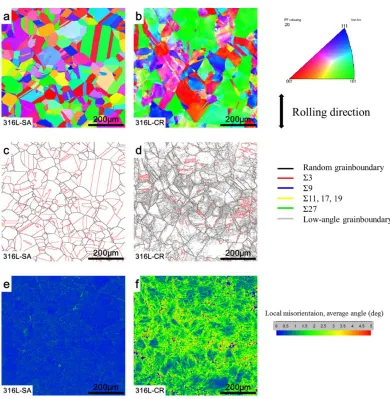
The grain boundary microstructures of 316L SS were observed by electron backscattering diffraction (EBSD) technique with scanning electron microscope (SEM). EBSD was measured with CamScan Apollo 300 thermal field emission scanning electron microscope (FESEM) equipped with Channel 5 of HKL EBSD system. The EBSD pattern was analyzed using Tango of Channel 5 software. Acceleration voltage of SEM beam for the EBSD measurement was 20 kV. The surface was finished by polishing with 1 μm diamond paste followed by electro-polishing using 20% HClO4 and 80% CH3COOH by volume electrolyte in order to obtain smooth surface free from surface hardening caused by the mechanical polishing. Any misorientation more than 2°was recognized as grain boundary. All types of grain boundaries are included as defining individual grains, and thus the twins were regarded as grains in this work. The CSL boundaries were defined according to the Palumbo-Aust's criterion (Δθmax = 15°Σ−5/6) [41].
3. RESULTS AND DISCUSSION
3.1 Microstructural characterization of 316L-SA and 316L-CR
Figure 1. The metallographic photos of (a) solution annealed 316L (316L-SA) and (b) cold rolled 316L (316L-CR).
[image:5.596.116.477.68.211.2] [image:5.596.102.492.284.683.2]
3.2 Potentiodynamic polarization results
3.2.1 Potentiodynamic polarization curves of 316L-SA and 316L-CR
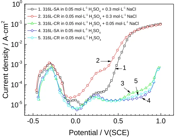
The anodic polarization curves for 316L-SA and 316L-CR in 0.05 mol/L H2SO4 and 0.05 mol/L H2SO4 + 0.3 mol/L NaCl solutions are shown in Fig. 3.
The anodic polarization curves for 316L-SA and 316L-CR in 0.05 mol/L H2SO4 solution exhibited two anodic current peaks. The first peak current was more than 20 times higher than the second peak current for both 316L-SA and 316L-CR. There was no significant difference between the anodic polarization curve of 316L-SA and that of 316L-CR, which indicated that the effect of cold roll on anodic polarization behavior of 316L SS was not remarkable. Active-passive transition was found on the anodic polarization curves for 316L-SA and 316L-CR in 0.05 mol/L H2SO4 + 0.3 mol/L NaCl solution. In the range from -0.135 to 0.700 V (SCE), the current density of 316L-CR was significantly higher than that of 316L-SA, showing a strong effect of cold roll on the anodic dissolution in this potential range. The effect of 0.3 mol/L chloride on anodic polarization behavior of 316L-CR was significantly stronger than that of 0.05 mol/L chloride. Coll roll accelerated the anodic dissolution of 316L SS in a certain potential range in dilute H2SO4 solution containing chlorides. Chlorides and cold roll had a synergistic effect on accelerating anodic dissolution.
-0.5 0.0 0.5 1.0
10-5 10-4 10-3 10-2 10-1 100
Curr
en
t d
en
si
ty
/ A·c
m
2
Potential / V(SCE)
1. 316L-SA in 0.05 mol·L-1
H2SO4 + 0.3 mol·L-1
NaCl 2. 316L-CR in 0.05 mol·L-1
H
2SO4 + 0.3 mol·L -1
NaCl 3. 316L-CR in 0.05 mol·L-1
H2SO4 + 0.05 mol·L-1
NaCl 4. 316L-SA in 0.05 mol·L-1
H2SO4 5. 316L-CR in 0.05 mol·L-1 H2SO4
1 2
3
4 5
· ·
Figure 3. The anodic polarization curves for 316L-SA and 316L-CR in 0.05 mol/L H2SO4 solutions with various chloride concentrations.
[image:6.596.133.438.388.628.2]
theory holds that the passivity breakdown was because of the competitive adsorption between chloride ions andhydroxide ions at the passive film surface [43, 44]. The penetration mechanism is that a high electrical field strength and a high concentration of defect in the disordered structure of the passive film affect the sub-surface insertion and transport of chloride ions through the passive film to the metal-oxide interface [45-47]. According to inhibiting healing mechanism, the alternative breakdown and repair of the passive film and the alternative chloride ions aggression lead to the pitting corrosion initiation [48, 49]. The point defect model has proposed that the chloride ions occupy the anion vacancies in the passive film which induced the anion vacancies decreasing and cation vacancies increasing [50, 51]. The passive film breaks down and pitting corrosion would initiate once enough cation vacancies amass at oxide-metal interface. In the present work, the difference of anodic behaviors between 316L-SA and 316L-CR were remarkable in sulfuric acid solution with a certain concentration of chloride because of the passive film breakdown induced by chloride, as shown in Fig 3.
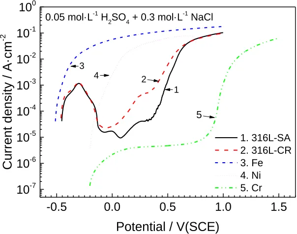
3.2.2 Potentiodynamic polarization curves for iron, chromium and nickel
Potentiodynamic polarization curves for iron, chromium and nickel in 0.05 mol/L H2SO4 + 0.3 mol/L NaCl solution are shown in Fig. 4. These results are to understand the effects of iron, chromium and nickel on the anodic polarization behavior of 316L SS. There was no active-passive transition in the anodic polarization curves of iron, nickel and chromium. Iron and nickel exhibited active dissolution in the whole potential range.
-0.5 0.0 0.5 1.0 1.5
10-7 10-6 10-5 10-4 10-3 10-2 10-1 100
5 0.05 mol·L-1 H2SO4 + 0.3 mol·L-1 NaCl
4 3
2
Curr
en
t d
en
si
ty
/ A·c
m
-2
Potential / V(SCE)
[image:7.596.135.437.456.694.2]1. 316L-SA 2. 316L-CR 3. Fe 4. Ni 5. Cr 1
There was a passive region from about 0.15 to 0.78 V (SCE) in the anodic polarization curve for chromium. These results show that the first current peak in the anodic polarization curve for 316L SS can be caused by the dissolution of iron and the passivating effect of chromium, and the difference of anodic behavior between 316L-SA and 316L-CR is related to the role of chromium. The competitive adsorption of Cl- and SO42- on metal surface at different anion ratios and concentrations may be one reason of the appearance of the second current peak.
Newman et al. [52] early reported a similar phenomenon that binary Fe-Cr alloys with chromium content no more than 17 at.% showed incomplete primary passivation in acid solutions, with a residual current which decreased with the increase of chromium content in the range of 8-12 at.%. For alloys containing chromium in the media with chlorides, it is difficult to form the Cr3+ complex due to the low stability constants [44]. Moreover, once the CrCl2+ complexes are formed, their dissolution rate is so slow that it would not increase the dissolution rate of relative to Cr3+ within an oxide matrix. Fe and Ni are easier to dissolve than Cr in a certain potential range. The critical condition for anodic dissolution and passivation of Fe-Cr-Ni alloys in a sulfuric acid solution with a high concentration of sodium chloride is strongly dependent on the alloy composition especially the Cr content.
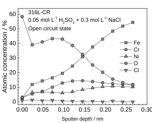
The effect cold roll and chromium content could reflect from the variation of surface film of 316L SS in sulfuric acid with chloride ions at open circuit surface. The variation in chemical composition with XPS depth profiles of iron, chromium, nickel and oxygen obtained from the XPS survey scans of the surfaces 316L-SA and 316L-CR specimens after the immersion in 0.05 mol/L H2SO4 + 0.3 mol/L NaCl solution for 3h at open circuit state are shown in Fig. 5.
0.00 0.05 0.10 0.15 0.20 0.25 0.30 0
10 20 30 40 50 60
a
316L-SA0.05 mol·L-1 H2SO4 + 0.3 mol·L-1 NaCl
Open circuit state
Atomic
co
nc
en
tra
tio
n /
%
Sputter depth / nm
0.00 0.05 0.10 0.15 0.20 0.25 0.30 0
10 20 30 40 50 60
Atomic
co
nc
en
tra
tio
n /
%
Sputter depth / nm
Fe Cr Ni O Cl 316L-CR
0.05 mol·L-1 H2SO4 + 0.3 mol·L-1 NaCl
Open circuit state
b
Figure 5. XPS depth profiles (at%) for iron, chromium, nickel, oxygen and chlorine in the surface films on (a) 316L-SA and (b) 316L-CR after immersion in 0.05 mol·L-1 H2SO4 + 0.3 mol·L-1 NaCl solution at open circuit states for 3h.
[image:9.596.141.447.85.332.2]Iron concentration increased while oxygen concentration decreased with increasing sputter depth. The concentration of chlorine was very low in the surfaces films. The place where oxygen concentration decreases to half of its initial value is defined as the thickness of oxide layer. The thickness of oxide layer on 316L-SA specimen was thicker than that on 316L-CR.
Table 2. Cr/Fe ratios in the film formed at open circuit states of 316L-SA and 316L-CR in 0.05 mol·L -1
H2SO4 + 0.3 mol·L-1 NaCl solution, from XPS depth profiles
Sputter depth (nm) Cr/Fe ratio
316L-SA 316L-CR
0 0.61 0.99
0.005 0.29 0.45
0.010 0.29 0.50
0.015 0.35 0.61
0.019 0.32 0.66
0.024 0.33 0.58
0.029 0.32 /
[image:9.596.86.511.547.735.2]
The chromium-to-iron ratio was higher in the film on 316L-CR specimen than on that 316L-SA, as shown in Table. 2. Phadnis [13] reported that whether in air or in 3.5% NaCl solution at open circuit potential or at pitting potential, the Cr/Fe ratio in the passive film formed on cold worked 304 stainless steel was higher than that of solution annealed 304 stainless steel from XPS analysis. This difference was because of the preferred orientation induced by cold work which may lead to the enhanced diffusion of Cr into the passivity layer to form a protective film with chromium enrichment.
3.3. Potentiostatic polarization results of 316L-SA and 316L-CR 3.3.1 Current vs. time curves
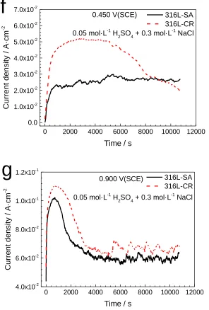
Current density vs. time curves for 316L-SA and 316L-CR in 0.05 mol/L H2SO4 + 0.3 mol/L NaCl solution under potentiostatic polarization at different potentials are shown in Fig. 6. Potentials -0.400 V (SCE), -0.160 V (SCE), -0.082 V (SCE) were respectively in the active dissolution region, the active-passive transition region and the passive region of the anodic polarization curve. At these three applied potentials, current densities for both 316L-SA and 316L-CR at first decreased with increasing polarization time and then reached a steady state. At -0.400 V (SCE), the steady current densities of 316L-SA and 316L-CR were similar and close to zero. At -0.160 V (SCE), the steady current densities of 316L-SA and 316L-CR were cathodic and close. At these two potentials, the true anodic current densities of 316L-SA and 316L-CR were low and therefore the measured current densities could be nearly zero or apparently cathodic, as shown in Fig. 6a and 6b. At -0.082 V (SCE), due the significant enhancing effect of cold roll on anodic dissolution, the measured current density can change from cathodic for 316L-SA to anodic for 316L-CR, as shown in Fig. 6c. The observation of the measured cathodic current was the result of a lower value of true anodic current than that of the true cathodic current at these potentials.
Potentials 0.074V (SCE), 0.295 V (SCE), 0.450 V (SCE) and 0.900 V (SCE) were in the potential region where cold roll had a significant effect on the anodic polarization curves of 316L stainless steel. At these four applied potentials, the current density vs. time curves were different from those at potentials of -0.400 V (SCE), -0.160 V (SCE) and -0.082 V (SCE). At 0.074 V (SCE), the current densities of 316L-SA and 316L-CR increased monotonically with time, and the current density of 316L-CR was higher than that of 316L-SA in the whole polarization period. At 0.295 V (SCE), 0.450 V (SCE) and 0.900 V (SCE), the current density of 316L-SA and 316L-CR increased firstly and then decreased. The maximum current densities of 316L-SA and 316L-CR increased while the correspond time for reaching the maximum current density decreased with increasing potential at 0.295V (SCE), 0.450V (SCE) and 0.900 V (SCE). It is noted that the actual surface area for active dissolution were changing in the process of potentiaostatic polarization when pitting occurred. The original electrode surface was used to obtain the apparent current density during potentiaostatic polarization.
in Fig. 6d-6g. Engell and Stolica [53] have proposed the following relation for the increase in current density, I, as a function of time, t, due to dissolution at a constant potential:
I ~ tb (1) Where b is a constant.
Szklarska-Smialowska and Janik-Czachor showed that b may vary from 2 to 6 depending upon experimental conditions for Fe13Cr and Fe16Cr alloys in Na2SO4 + NaCl environments [25].
0 2000 4000 6000 8000 10000 12000
0.0 1.0x10⁻⁴ 2.0x10⁻⁴ 3.0x10⁻⁴ 4.0x10⁻⁴
0 2 4 6 8 10
3.0x10⁻⁴
3.5x10⁻⁴
4.0x10⁻⁴
a
Curr
en
t d
en
si
ty
/ A·c
m
-2
Time / s
-0.400 V (SCE) 316L-SA
316L-CR 0.05 mol·L-1 H2SO4 + 0.3 mol·L-1 NaCl
0 2000 4000 6000 8000 10000 12000
-5.0x10⁻⁵ 0.0 5.0x10⁻⁵ 1.0x10⁻⁴ 1.5x10⁻⁴
0 2 4 6 8 10
1.0x10⁻⁴
1.2x10⁻⁴
1.4x10⁻⁴
Curr
en
t d
en
si
ty
/ A·c
m
-2
Time / s
-0.160 V(SCE) 316L-SA
0 2000 4000 6000 8000 10000 12000
-2.0x10⁻⁵ 0.0 2.0x10⁻⁵ 4.0x10⁻⁵ 6.0x10⁻⁵ 8.0x10⁻⁵ 1.0x10⁻⁴
Time / s
Curr en t d en si ty / A·c m -2
0.05 mol·L-1 H2SO4 + 0.3 mol·L-1 NaCl
0 2 4 6 8 10
6.0x10⁻⁵
8.0x10⁻⁵
1.0x10⁻⁴
c
-0.082 V(SCE) 316L-SA316L-CR
0 2000 4000 6000 8000 10000 12000
0.0 2.0x10⁻³ 4.0x10⁻³ 6.0x10⁻³ 8.0x10⁻³ 1.0x10⁻²
Time / s
Curr en t d en si ty / A·c m -2
0.05 mol·L-1 H2SO4 + 0.3 mol·L-1 NaCl
d
0.074 V(SCE) 316L-SA316L-CR
0 2000 4000 6000 8000 10000 12000
0.0 5.0x10⁻³ 1.0x10⁻² 1.5x10⁻² 2.0x10⁻² 2.5x10⁻² 3.0x10⁻²
Time / s
Curr en t d en si ty / A·c m -2
0.05 mol·L-1 H2SO4 + 0.3 mol·L-1 NaCl
e
316L-SA316L-CR
0 2000 4000 6000 8000 10000 12000
0.0 1.0x10⁻² 2.0x10⁻² 3.0x10⁻² 4.0x10⁻² 5.0x10⁻² 6.0x10⁻² 7.0x10⁻²
0.05 mol·L-1 H2SO4 + 0.3 mol·L-1 NaCl
Time / s
Curr
en
t d
en
si
ty
/ A·c
m
-2
f
0.450 V(SCE) 316L-SA316L-CR
0 2000 4000 6000 8000 10000 12000
4.0x10⁻² 6.0x10⁻² 8.0x10⁻² 1.0x10⁻¹ 1.2x10⁻¹
Time / s
Curr
en
t d
en
si
ty
/ A·c
m
-2
0.05 mol·L-1 H2SO4 + 0.3 mol·L-1 NaCl
g
0.900 V(SCE) 316L-SA316L-CR
Figure 6. The potentiostatic polarization curves for 316L-SA and 316L-CR in 0.05 mol·L-1 H2SO4 + 0.3 mol·L-1
NaCl solution at (a) -0.400 V(SCE), (b) -0.160 V(SCE), (c) -0.082 V(SCE), (d) 0.074V(SCE), (e) 0.295 V(SCE), (f) 0.450 V(SCE) and (g) 0.900 V(SCE).
Our results showed that both cold roll and applied potentials affect the electrochemical reaction kinetics of 316L SS under potentiostatic polarization.
[image:13.596.139.435.84.522.2]
more anodic potentials.
3.3.2 ICP analysis of dissolved Fe, Cr and Ni in solutions after potentiostatic polarization
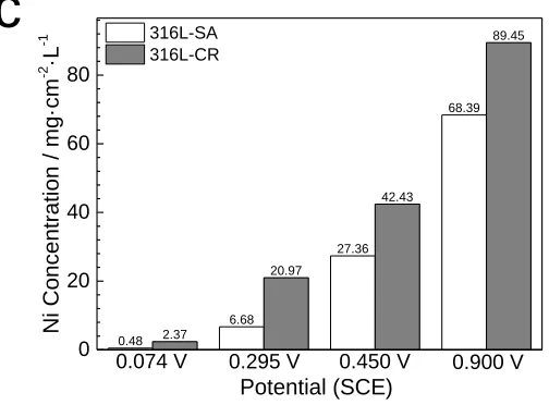
The concentrations of dissolved Fe, Cr and Ni in the solutions after potentiostatic polarization at 0.074 V (SCE), 0.295 V (SCE), 450 V (SCE) and 0.900 V (SCE) for 3 h determined by ICP-OES are shown in Fig. 7. The amounts of dissolved Fe, Cr and Ni in solutions increased with increasing applied potential. The amounts of dissolved Fe, Cr, and Ni in the solutions for 316L-CR were higher than those for 316L-SA at each potential. The ratio of dissolved amounts of Fe, Cr and Ni in solutions for 316L-CR to those of 316L-SA decreased with applied potential. It is summarized that the cold roll and increase of applied potentials accelerated the anodic dissolution of 316L SS, and the effect of cold roll was more obvious under lower potentials. The ICP results were in agreement with the results of current vs. time curves under potentiostatic polarization. Zhang et al. [91] found similar phenomenon that the dissolved element concentrations of NiCoCrMo alloy immersed in HF solution were accelerated by increase of cold forge degree via ICP analysis.
3.64 44.03 178.67 432.26 16.58 137.57 275.53 576.42 0 100 200 300 400 500 600 0.074 V Fe Con ce ntr ati on / mg ·c m -2 ·L -1 Potential (SCE) 316L-SA 316L-CR
0.295 V 0.450V 0.900V
a
0.86 11.21 45.02 109.8 3.95 34.63 69.48 146.48 0 25 50 75 100 125 150b
316L-SA316L-CR Cr Con ce ntr ati on / mg ·c m -2 ·L -1 Potential (SCE)
0.48
6.68
27.36
68.39
2.37
20.97
42.43
89.45
0 20 40 60 80
c
316L-SA316L-CR
Ni Con
ce
ntr
ati
on
/ mg
·c
m
-2 ·L
-1
Potential (SCE)
0.074 V 0.295 V 0.450 V 0.900 V
Figure 7. ICP-OES results of the dissolved amounts of (a) Fe, (b) Cr and (c) Ni in solutions after potentiostatic polarization at 0.074 V(SCE), 0.295 V(SCE), 0.450 V(SCE) and 0.900 V(SCE) for 3 h.
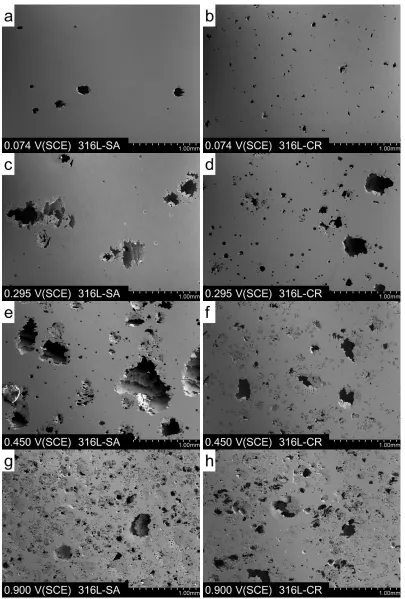
3.3.3 Surface morphologies after potentiostatic polarization
The electrode surfaces of 316L-SA and 316L-CR were bright and no pitting was found after potentiostatic polarization for 3 h at -0.400, -0.160 and -0.082 V (SCE), corresponding to low values of current densities at these potentials for both 316L-SA and 316L-CR.
[image:15.596.159.411.87.273.2][image:16.596.97.502.66.665.2]
According to a model developed by Laycock et al. [66,67], these different pits morphologies suggested the inhomogeneous local current densities within different regions of growing pits at different pit growth periods. Meanwhile, secondary pits were found at the bottom of big open pits. A stable pit had a large enough volume after a long enough propagation time, and repassivation tended to occur on the pit side wall, favoring the initiation of a new pit or secondary cavity at the pit bottom [89].
3.3.4 The effect of cold roll and applied potentials
Some metallurgical factors such as crystal defects and compositions affect the properties of bulk material and the integrity of passive films formed in environment mediums, and hence the localized corrosion resistance of the alloy [68]. Cold work could result in some metallurgical modifications such as the creation and slipping of dislocations, producing inclusions, elongation, or fractures at the interface with the matrix [3]. The presence of inclusion in stainless steel increased the susceptibility of pit formation [69]. The chemical composition changes around sulphide inclusions in stainless steel which lead to high dissolution rate of sulphide inclusions are likely to be the cause of initiation of pitting corrosion [70,71]. Pitting initiated from the local dissolution of MnS at the interface of the MnS and MnCr2O4 nano-octahedron embedded in the MnS [72,73]. The rolling process lead to stretched inclusions [74]. The shapes of inclusion and cracks in the inclusions or micro-cracks between the matrix and the inclusion produced by plastic deformation [75,76] may affect the initiation of pitting [8]. Inclusion size largely affects the frequency and lifetime of unstable micro-pits, and dissolution kinetics in the early stages of pitting is affected by inclusion shape [77]. Yu et al. [78,79] reported that inclusions elongated along the rolling direction and compress along the thickness direction during multi-pass cold rolling process. The inclusion deformation and non-uniform deformation around the uniform deformation increased with inclusion sizes. There would be cracks around hard inclusions but no cracks existed around soft inclusions under the rolling conditions. Suter et al. [74] investigated the combination of stress and the presence of MnS inclusions effect on the onset of pitting in 304 SS, it was found that stress shifted the pitting potential to more negative. A single, shallow MnS inclusion showed metastable pitting, and a single deep MnS inclusions showed active pitting. Applied stress induced cracks which allowed higher concentrations of aggressive species causing stable pitting. All these results suggested the effect of inclusion on the pitting of non-cold worked and cold worked stainless steels.
induced passivity breakdown based on the role of the inter-granular boundaries (or defective boundaries) of the barrier oxide layer on the redistribution of the potential at the metal/oxide/electrolyte interfaces in the passive state. According to this model, the defect region is easier for ion transferring and the ionic conductivities of oxide formed in the defective sites are many orders of magnitude higher than that of the bulk oxide. The oxide film formed at the interface between the “defect-free” matrix and the defects is sensitive to breakdown. Therefore, the potential drop at the oxide on the interface between the “defect-free” matrix and defects is lower and it is easier for the oxide film to breakdown.
The anodic current densities of 316L-CR were generally higher than those of 316L-SA at the potentials where pitting occurred. It implies that the local dissolution rate of 316L SS becomes higher in the cold worked state, which is confirmed by the ICP analysis of solutions after the potentiostatic polarization tests, as shown in Fig. 7. Higher defect density ( higher Low angle grain boundary density, higher local mistorientation, cracks around inclusions) caused by cold rolling as the result of cold roll in 316L-CR might make the oxide film easier to breakdown and provide more priority nucleation sites for pitting. A larger pit number in 316L-CR than in 316L-SA is one of the reasons for the higher anodic dissolution rate in 316L-CR than in 316L-SA. The increase of the amount of free metal cations inside the pit and the acceleration of the diffusion of chlorides into the pit would also contribute.
4. CONCLUSIONS
1. Cold roll decreased the Σ3 CSL grain boundaries proportion and increased the local misorientation in 316L stainless steel. The enhancing effect of cold roll on the anodic dissolution of 316L stainless steel in 0.05 mol/L H2SO4 + 0.3 mol/L NaCl solution was significant in the potential range from -0.135 to 0.700 V (SCE). The effect of cold roll was more significant in sulfuric acid solution with chlorides than in chloride-free solution.
2. The current densities under potentiostatic polarization, pits numbers and open pit diameters increased with increasing applied potentials for both 316L-SA and 316L-CR. Cold roll increased the number of pits and decreased the pit size at a certain applied potential.
3. The ICP results of the tested solutions after the potentiostatic polarization were in agreement with the results of current vs. time curves for both 316L-SA and 316:-CR
ACKNOWLEDGEMENTS
This work was supported by the International Cooperative Project sponsored by Science and Technology Commission of Shanghai Municipality, China (13520721200), Specialized Research Fund for the Doctoral Program of Higher Education, China (20123108110021), and National Natural Science Foundation of China (51571138). The support from the Instrument Analytical and Research Center, Shanghai University.
References
1. A. Barbucci, G. Cerisola, P. L. Cabot, J. Electrochem. Soc., 149 (2002) B534.
2. B. Mazza, P. Pedeferri, D. Sinigaglia, A. Cigada, L. Lazzari, G. Re, D. Wenged, J. Electrochem. Soc., 123 (1976) 1157.
3. L. Peguet, B. Malki, B. Baroux, Corros. Sci., 49 (2007) 1933. 4. H. H. Uhlig, Corrosion, 19 (1963) 231t.
5. K. Osozawa, H. J. Engell, Corros. Sci., 6 (1966) 389.
6. W. Tian, N. Du, S. Li, S. Chen, Q. Wu, Corros. Sci., 85 (2014) 372.
7. B. Mazza, P. Pedeferri, D. Sinigaglia, A. Cigada, G. Fumagalli, G. Re, Corros. Sci., 19 (1979) 907. 8. B. Mazza, P. Pedeferri, D. Sinigaglia, A. Cigada, G. A. Mondora, G. Re, G. Taccani, D. Wenger, J.
Electrochem. Soc., 126 (1979) 2075.
9. D. Sinigaglia, B. Vicentini, G. Taccani, G. Salvago, G. Dallaspezia, J. Electrochem. Soc., 130 (1983) 991.
10.A. Cigada, B. Mazza, P. Pedeferri, D. Sinigaglia, J. Biomed. Mater. Res., 11 (1977) 503. 11.G. Salvago, G. Fumagalli, D. Sinigaglia, Corros. Sci., 23 (1983) 515.
12.C. J. Semino, P. Pedeferri, G. T. Burstein, T. P. Hoar, Corros. Sci., 19 (1979) 1069.
13.S. V. Phadnis, A. K. Satpati, K. P. Muthe, J. C. Vyas, R. I. Sundaresan, Corros. Sci., 45 (2003) 2467.
14.B. C. Syrett, S. S. Wing, Corrosion, 34 (1978) 138.
15.V. A. C. Haanappel, M. F. Stroosnijder, Corrosion, 57 (2001) 557.
16.B. R. Kumar, R. Singh, B. Mahato, P. K. De, N. R. Bandyopadhyay, D. K. Bhattacharya, Mater. Charact., 54 (2005) 141.
18.G. Hu, C. Xu, X. Zhang, Y. Luo, D. Wang, J. Chin. Soc. Corros. Prot., 22 (2002) 7. 19.C. Xu, X. Zhang, G. Hu, Chinese J. Chem. Eng., 54 (2003) 790.
20.U. Kamachi Mudali, P. Shankar, S. Ningshen, R. K. Dayal, H. S. Khatak, B. Raj, Corros. Sci., 44 (2002) 2183.
21.H. Yu, Y. Zhang, A. Lü, C. Liu, Mater. Sci. Tech.-Lond, 2010) 202. 22.H. Yu, Y. Zhang, A. Lü, C. Liu, J. Mater. Metall., 2009) 69.
23.F. Navaï, J. Mater. Sci., 30 (1995) 1166.
24.F. Navaï, O. Debbouz, J. Mater. Sci., 34 (1999) 1073.
25.Z. Szklarska-Smialowska, M. Janik-Czachor, Br. Corros. J., 4 (1969) 138. 26.A. Randak, F. W. Trautes, Mater. Corros., 21 (1970) 97.
27.P. Forchhammer, H. J. Engell, Mater. Corros., 20 (1969) 1. 28.R. Štefec, F. Franz, Corros. Sci., 18 (1978) 161.
29.D. Nakhaie, M. H. Moayed, Corros. Sci., 80 (2014) 290.
30.Newman, R. C. Corrosion Mechanisms in Theory and Practice, 3rd ed., CRC Press, Boca Raton (2012).
31.R. N. Parkins, Corrosion, 43 (1987) 130.
32.P. L. Andresen, F. Peter Ford, Mater. Sci. Eng., A, 103 (1988) 167. 33.R. C. Newman, Corrosion, 50 (1994) 682.
34.T. Shoji, Z. Lu, H. Murakami, Corros. Sci., 52 (2010) 769.
35.Z. Lu, T. Shoji, F. Meng, H. Xue, Y. Qiu, Y. Takeda, K. Negishi, Corros. Sci., 53 (2011) 1916. 36.Z. Lu, T. Shoji, Y. Takeda, Y. Ito, A. Kai, S. Yamazaki, Corros. Sci., 50 (2008) 561.
37.Z. Lu, T. Shoji, F. Meng, Y. Qiu, T. Dan, H. Xue, Corros. Sci., 53 (2011) 247. 38.F. Meng, Z. Lu, T. Shoji, J. Wang, E. Han, W. Ke, Corros. Sci., 53 (2011) 2558. 39.N. Cansever, A. F. Ca k r, M. Ürgen, Corros. Sci., 41 (1999) 1289.
40.M. Finšgar, J. Jackson, Corros. Sci., 86 (2014) 17.
41.G. Palumbo, K. T. Aust, Acta Metall. Mater., 38 (1990) 2343. 42.G. S. Frankel, J. Electrochem. Soc., 145 (1998) 2186.
43.H. P. Leckie, H. H. Uhlig, J. Electrochem. Soc., 113 (1966) 1262.
44.Strehblow, H.; Marcus, P. Corrosion Mechanisms in Theory and Practice, 3rd ed., CRC Press, Boca Raton (2012).
45.D. D. Macdonald, Pure Appl. Chem., 71 (1999) 951.
46.M. Urquidi, D. D. Macdonald, J. Electrochem. Soc., 132 (1985) 555.
47.L. F. Lin, C. Y. Chao, D. D. Macdonald, J. Electrochem. Soc., 128 (1981) 1194.
48.A. Bouzoubaa, B. Diawara, V. Maurice, C. Minot, P. Marcus, Corros. Sci., 51 (2009) 2174. 49.B. MacDougall, J. Electrochem. Soc., 126 (1979) 919.
50.M. A. Amin, Electrochim. Acta, 54 (2009) 1857.
51.D. D. Macdonald, J. Electrochem. Soc., 139 (1992) 3434.
52.R. C. Newman, F. T. Meng, K. Sieradzki, Corros. Sci., 28 (1988) 523. 53.H. J. Engell, N. D. Stolica, Z. Phys. Chem., 20 (1959) 113.
54.S. M. Ghahari, A. J. Davenport, T. Rayment, T. Suter, J. Tinnes, C. Padovani, J. A. Hammons, M. Stampanoni, F. Marone, R. Mokso, Corros. Sci., 53 (2011) 2684.
55.M. Ghahari, D. Krouse, N. Laycock, T. Rayment, C. Padovani, M. Stampanoni, F. Marone, R. Mokso, A. J. Davenport, Corros. Sci., 2015)
56.P. Ernst, R. C. Newman, Corros. Sci., 44 (2002) 927. 57.P. Ernst, R. C. Newman, Corros. Sci., 44 (2002) 943.
58.P. Ernst, N. J. Laycock, M. H. Moayed, R. C. Newman, Corros. Sci., 39 (1997) 1133. 59.P. C. Pistorius, G. T. Burstein, Phil. Trans. R. Soc. Lond. A, 341 (1992) 531.
60.G. S. Frankel, L. Stockert, F. Hunkeler, H. Boehni, Corrosion, 43 (1987) 429. 61.J. Mankowski, Z. Szklarska-Smialowska, Corros. Sci., 15 (1975) 493.
63.H. S. Isaacs, G. Kissel, J. Electrochem. Soc., 119 (1972) 1628. 64.I. L. Rosenfeld, I. S. Danilov, Corros. Sci., 7 (1967) 129. 65.W. Schwenk, Corrosion, 20 (1964) 129t.
66.N. J. Laycock, S. P. White, J. Electrochem. Soc., 148 (2001) B264. 67.N. J. Laycock, J. Electrochem. Soc., 145 (1998) 1101.
68.R. P. M. Procter, 1994) 49.
69.M. A. Baker, J. E. Castle, Corros. Sci., 34 (1993) 667.
70.D. E. Williams, Y. Y. Zhu, J. Electrochem. Soc., 147 (2000) 1763.
71.D. E. Williams, M. R. Kilburn, J. Cliff, G. I. N. Waterhouse, Corros. Sci., 52 (2010) 3702. 72.B. Zhang, J. Wang, B. Wu, Y. T. Zhou, X. L. Ma, Corros. Sci., 2015)
73.S. J. Zheng, Y. J. Wang, B. Zhang, Y. L. Zhu, C. Liu, P. Hu, X. L. Ma, Acta Mater., 58 (2010) 5070.
74.T. Suter, . G. ebb, H. B hni, R. C. Alkire, J. Electrochem. Soc., 148 (2001) B174. 75.V. Vignal, R. Oltra, C. Josse, Scripta Mater., 49 (2003) 779.
76.E. Rozovsky, W. C. Hahn, B. Avitzur, Metall. Trans., 4 (1973) 927. 77.J. Stewart, D. E. Williams, Corros. Sci., 33 (1992) 457.
78.H. Yu, X. Liu, H. Bi, L. Chen, J. Mater. Process. Tech., 209 (2009) 455.
79.H. Yu, H. Bi, X. Liu, L. Chen, N. Dong, J. Mater. Process. Tech., 209 (2009) 4274. 80.M. H. Lewis, B. Hattersley, Acta Metallurgica, 13 (1965) 1159.
81.B. I. Kolodii, Mater. Sci+, 36 (2000) 884.
82.N. Pineau, C. Minot, V. Maurice, P. Marcus, Electrochem. Solid-State Lett., 6 (2003) B47. 83.P. Marcus, V. Maurice, H. H. Strehblow, Corros. Sci., 50 (2008) 2698.
84.G. S. Frankel, N. Sridhar, Mater. Today, 11 (2008) 38.
85.G. T. Burstein, C. Liu, R. M. Souto, S. P. Vines, Corros. Eng., Sci. Technol., 39 (2004) 25. 86.Y. Gonz lez-Garc a, G. T. Burstein, S. Gonz lez, R. M. Souto, Electrochem. Commun., 6 (2004)
637.
87.G. T. Burstein, P. C. Pistorius, S. P. Mattin, Corros. Sci., 35 (1993) 57. 88.P. C. Pistorius, G. T. Burstein, Corros. Sci., 33 (1992) 1885.
89.W. Tian, S. Li, N. Du, C. Sibing, Q. Wu, Corros. Sci., 93 (2015) 242.
90.Y. A. Albrimi, A. Eddib, J. Douch, Y. Berghoute, M. Hamdani, R. M. Souto, Int. J. Electrochem. Sci., 6 (2011) 4614.