Int. J. Electrochem. Sci., 8 (2013) 4098 - 4109
International Journal of
ELECTROCHEMICAL
SCIENCE
www.electrochemsci.org
IPMC Based Biosensor for the Detection of Biceps Brachii
Muscle Movements
Kiwon Park1, Bonghwan Lee1, Hyung-Man Kim1,*, Kap-Seung Choi2, Gunyong Hwang2, Gi-Sig Byun3 and Hyung-Ki Lee3
1
Department of Mechanical Engineering & High Safety Vehicle Core Technology Research Center, INJE University, 607 Eobang-dong, Gimhae-si, Gyongsangnam-do 621-749, Republic of Korea
2
Department of Green Automobile Engineering, Youngsan University, 288 Junam-dong, Yangsan-si, Kyungnam-do 626-790, Republic of Korea
3
Department of Control and Instrumentation Engineering, Pukyong Natonal University, Busan 608-737, Republic of Korea
*
E-mail: mech-khm@inje.ac.kr
Received: 30 January 2013 / Accepted: 21 February 2013 / Published: 1 March 2013
Ionic polymer-metal composite (IPMC) consists of a polyelectrolyte film both-surfaces plated by metallic electrodes. When the IPMC bends, a voltage is generated between the two electrodes across the membrane. Although the IPMC is a promising soft sensor applicable to biomedical application, it still requires a further signal processing technique to effectively measure the deflections. The present study investigated an IPMC sensor model based on a RC circuit that can be easily applicable to the detection of muscle movements. The RC circuit model, describing a physical composition of the IPMC, contains a current source that relates the amount of charge differences accumulated on each electrode to the applied bending angles. The effectiveness of the model was tested by comparing the reproduced bending angles from the inverse model with the real bending angles. Finally, the sensor system was applied to the detection of biceps brachii muscle movements that causes elbow flexion, and the results was compared with the conventional electromyography (EMG) method to identify the potential of the IPMC as a biomedical sensor.
Keywords: IPMC sensor, Circuit model, Model identification, Surface-mounted sensor, EMG
1. INTRODUCTION
conductance and corrosion resistance [1-5]. In the Nafion® based IPMC; SO3- is the ionic termination
on the side branches of backbone polymer. Therefore, only the cations and solvent can move in the membrane while the anions, SO3- groups, are fixed at the backbone polymer. In a wet condition, the
cations are surrounded by water molecules due to the electrostatic force interacting between the oxygen atoms of the water molecules and the cations. The hydrated cations and anions also form conjugate pairs in the absence of any mechanical and electrical stimuli [1].
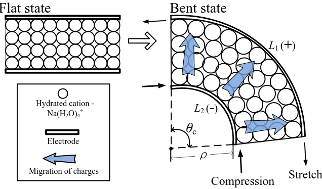
When the IPMC is bent mechanically, the hydrated cations on the compressed side of membrane move towards the stretched side of the membrane, resulting in the imbalances in the number of cations contacting each electrode, and this produces output voltages across the membrane, as depicted in Fig. 1.
Flat state
Stretch Compression
Bent state
L2 (-)
L1 (
+
)θ
cρ
Hydrated cation - Na(H2O)4
+
Electrode
[image:2.596.139.457.265.452.2]Migration of charges
Figure 1. Illustration of operating mechanism of IPMC sensor.
Since the IPMC is a soft and non-toxic hydrophilic material, it has a great potential for biomedical applications such as surface mounted sensors for muscle movement detections [2, 3]. However, the characteristics of the IPMC sensor have investigated by fewer researchers than those of the IPMC actuator [4-8], and most research efforts on IPMC sensor have been made on developing models for the sensor, which simulated output voltages or output currents corresponding to the tip displacement [2-9, 11-16]. One of the main assumptions in the models is that the charge density variation inside the membrane is linearly dependent on the induced stress [12-14, 16-18].
was realized in an analog electric circuit using operational amplifiers. The surface mounted IPMC sensor successfully detected elbow flexion and extension, and its performance was compared with that of the conventional electromyography (EMG) method for the detection of muscle movement.
The main contribution of this paper is the development of a practical model of IPMC sensor which is easily applicable to real world. Another contribution is that the performance of the IPMC sensor is demonstrated in a real biomedical application, which shows that further biomedical applications of the IPMC sensor are possible.
2. MODELING OF IPMC SENSOR
In the present study, we assumed that the membrane maintained the number of cations before and after the bending motion. The relationship between the amount of net charges (q) and applied bending angles (θB) can be explained by a geometric diagram, as shown in Fig. 1. When IPMC is bent
by a bending angle (θB), the number of hydrated cations increases on the stretched side of electrode
and decreases on the compressed side of electrode. Therefore, the amount of net charge (q) produced at the bent electrodes is assumed to be proportional to the difference in area (∆S) between the area of stretched and compressed side of electrodes.
Based on the diagram in Fig. 1, the length of each electrode can be found as
180 ) ( 1
C t
L , (1)
180 2
C
L , (2)
where is the radius of curvature at the deformed inside surface of the electrode and the membrane thickness (t) is assumed to be constant. θC is the arc angle and L1 and L2 represent the
lengths of inside and outside electrode, respectively. The expression for the difference of area (∆S) is obtained as
)
(L1 L2
b
S
, (3)
where b represents the width of the IPMC. In particular, the linear relationship between the bending angle (θB) and the arc angle (θC) is assumed as
B
C
, (4)
where α is coupling constant between the angles.
B
180 tb
q , (5)
For a further simplification, Eq. (5) can be rewritten using an aggregated constant as
B
K
q
, (6)After taking the time derivative of Eq. (6), the relationship between the current (I) generation and the bending angle (θB) can be obtained as
dt d K
I B . (7)
R
e2C
R
cR
e1V
o
R
dt
dθ
K
I
BZ
TFigure 2. Circuit model of the IPMC sensor.
Fig. 2 shows the circuit model of IPMC sensor that has the current source expressed by Eq. (7). The circuit model is connected to the measurement device through the resistances (Re1 and Re2) acting
as the resistances along the surface of the IPMC. Since the polymer membrane is sandwiched between the two electrodes, the IPMC has a capacitance (C), as shown in Fig. 2. Rc represents an ion diffusion
resistance, and R represents the resistance of polymer.
Because the input buffer resistance of DAQ is much greater than the surface resistances of IPMC, the effects of Re1 and Re2 are ignored for the simplification of the model. Then, the output
voltage (Vo) is written by
T o IZ
V , (8)
[image:4.596.119.433.245.494.2]1 ) ( C R R s R C sRR Z c c
T , (9)
After assuming all the initial conditions are zero, the governing differential equation between the input bending angle (θB) and the output voltage (Vo) is represented by
B c B c c o c o C R R KR R R KRR V C R R
V
) (
) (
1
. (10)
The model described in (10) was tested using Simulink in Matlab®.
3. EXPERIMENTAL PART
3.1 Output Signal Measurement
IPMC was fabricated using a Nafion® 117 membrane with a thickness of 178 µm and platinum particles. The particles were electrolessly plated on both sides of the membrane by the method in [18] that was originally proposed by Dr. Oguro [19]. After the fabrication procedure, the IPMC was cut into a size of 20 mm × 3 mm for the experiment.
V
oθ
BIPMC
Electrode
θ
BClamp Disc rotation
Center of disc Guider DAQ Stepper motor Potential meter
Motor shaft rotation
Figure 3. Illustration of experimental setup.
[image:5.596.133.468.422.618.2]
The bending angle was defined by θB in Fig. 3 to describe the tip displacement of the sensor. Note that
the bending angle is proportional to the rotation angle of the stepper motor shaft. The bending angles were also measured simultaneously by a potentiometer which was placed at the end of the motor shaft.
The stepper motor was controlled by a microprocessor (PIC 16F876, Microchip). The output voltage of the sensor and the bending angle data from the potentiometer were acquired via a data acquisition board (NI USB-6211, National Instruments). Matlab® was used to control the data acquisition board to collect data.
3.2 Parameter Estimation
The model was tested by using Matlab®, and parameters were also estimated in time domain by minimizing the RMS error between the output signal from the real sensor and the simulated output signal from the model. The reproduced bending angle (θR) was calculated using the inverse model of
the sensor.
3.3 EMG Measurement
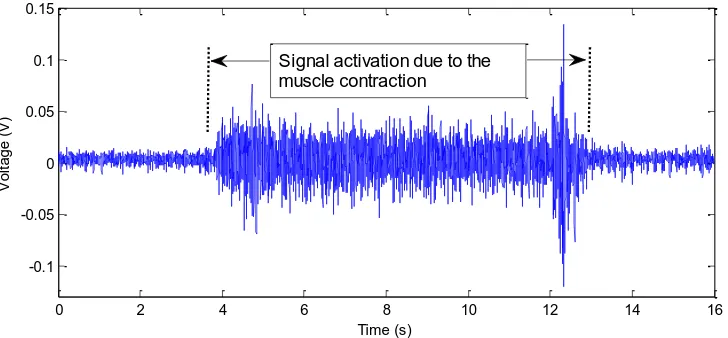
In order to acquire EMG corresponding to the elbow flexion and extension, a pair of adhesive silver/silver chloride (Ag/AgCl) snap-electrodes (BIOPAC Systems, Inc.) was placed over the biceps brachii muscle of the human upper arm that acts to flex the elbow. Data recording began about 4 sec. prior to the motion of forearm. The flexion of elbow lasted about 8 sec. and then extended to the starting position. The total recording time was 16 sec. The electromyogram was recorded using a BIOPAC® MP35 data acquisition unit.
[image:6.596.135.462.523.724.2]3.4 Output Signal Measurement from the Surface-mounted IPMC
One end of the IPMC was inserted into a thin plastic clamp in which metallic copper foils contacted the electrodes of the IPMC to transmit the electric signal across the IPMC sensor. Then, the IPMC was coated together with the clamp using thin silicone membranes with a thickness of 150μm to retain the solvent inside the IPMC during the experiment, as shown in Fig. 4. The IPMC sensor was then placed on an adhesive tape and attached over the biceps brachii muscle.
Figure 5. The inverse circuit model of IPMC sensor.
In order to realize the inverse model, the analog circuit shown in Fig. 5 was built and tested. The part 1 is for converting the output from IPMC sensor (Vo) to the current (I) in Fig. 2, using
the inverted amplification relationship between Vo and Vx, which is represented as
T X o
X
Z R V
V
, (11)
Since I=Rx/Vx,
T o
Z V
I . (12)
The transfer function of the integrator in part 2 represents the inverse of charge model in Eq. (7), which converts the current (I) to the voltage proportional to the reproduced bending angle (θR).
The output voltage (VIO) from the integrator is
V dt
C R
V X
I I IO
1
, (13)
[image:7.596.79.522.181.333.2]
Idt
C R R V I I X
IO . (14)
The bending angles corresponding to the elbow flexion and extension were monitored by measuring the VIO from the analogue circuit.
4. RESULT AND DISCUSSION
4.1 Output Signals from the Model and Inverse Model
0 0.5 1 1.5 2 2.5 3 3.5 4
-0.1 0 0.1 Time (s) V o lt a g e ( V )
0 0.5 1 1.5 2 2.5 3 3.5 4
0 20 40 Time (s) A n g le ( d e g re e )
0 2 4 6 8 10 12 14 16 18 20
[image:8.596.103.520.276.573.2]0 10 20 30 Time (s) A n g le ( d e g re e ) Real Model Real Inv model Real Inv model (a) (c) (b)
Figure 6. Simulation results of output voltage and bending angles.
[image:9.596.48.553.159.277.2]
exponential decays although some negligible differences are observed between the real and the simulated signal.
Table 1. Estimated parameters.
Parameters Value
C (mF)
3.10 Rc (Ω)
5.01×10 R (KΩ)
4.42 K (C/θB)
1.20×10⁻⁷
Fig. 6(b) shows the reproduced step bending angles (θR) from the inverse transfer function of
the model. In order to validate the effectiveness of bending angle reproduction using the inverse model, we applied an arbitrary bending motion to the sensor by randomly rotating the stepper motor shaft. Fig. 6(c) shows the real and the reproduced arbitrary bending angles. The results show that the inverse model reproduces the trend of bending angle variations fairly well, which implies that the behavior of IPMC sensor can be explained using the proposed model.
4.2 Output Signals from the Surface-mounted IPMC
0 2 4 6 8 10 12 14 16
-0.1 -0.05 0 0.05 0.1 0.15
Time (s)
V
o
lt
a
g
e
(
V
)
Signal activation due to the muscle contraction
Figure 7. EMG measured on biceps brachii.
[image:9.596.112.476.469.638.2][image:10.596.63.533.138.497.2]
After the elbow is extended and relaxes, no activation of output signals is observed. Since the biceps brachii muscle is not the main muscle that acts to extend the elbow, no significant activations of output signals are observed during the extension [20, 21].
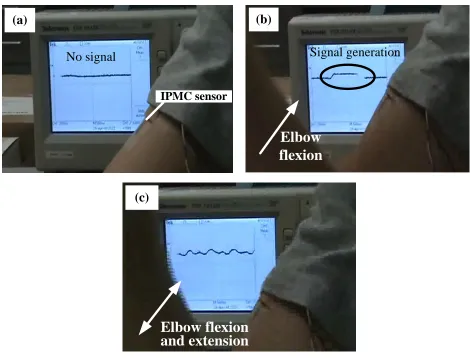
Figure 8. Output signals from the IPMC sensor placed over the biceps brachii muscle.
Fig. 8 shows the output signals from the IPMC sensor placed on the same place for EMG measurement during elbow flexion and extension. During the forearm is being extended resting on the table, no output signals are detected since the IPMC is not deformed, as shown in Fig. 8(a). During the elbow flexion, the surface over the muscle swells corresponding to the contraction of muscle, which causes bending motion of the IPMC sensor resulting in the generation of output signals as shown in Fig. 8(b). While the elbow flexion and extension are repeated, the biceps brachii muscle is contracted and stretched causing continuous bending motion of the IPMC; therefore the output signal is oscillating corresponding to the motion as shown in Fig. 8(c).
In the experimental result, EMG method better detected muscle contractions than the extensions since myoelectric signals are mostly generated by the contraction of muscles. On the other hand, the output from the IPMC sensor detected both muscle contraction and extension at the same place on the body, corresponding to the elbow flexion and extension.
No signal
(a)
IPMC sensor
Signal generation
(b)
Elbow
flexion
(c)
5. CONCLUSIONS
In this study, an effective monitoring method of the bending angles applied on the IPMC sensor was investigated using circuit models. The performance of output voltages fairly well and the corresponding inverse model also reproduced the input bending angles without significant errors.
An IPMC sensor was applied to the monitoring of curvature variations at a surface of upper arm due to the muscle movement during elbow flexion and extension. When compared with the conventional EMG technique, the IPMC produced more noiseless signals with a good signal to noise ratio corresponding to the motion of elbow even under the extension of muscle in which only poor myoelectric signals were detected with the EMG technique.
This study provided the potential of IPMC sensor for biomedical applications. Their unique attributes and favorable responses demonstrated in this study show their high potential as not only a bending sensor but also a surface mounted sensor on a human body.
ACKNOWLEDGMENTS
This work was partly supported by the New & Renewable Energy of the Korea Institute of Energy technology Evaluation and Planning (KETEP) grant funded by the Korea government Ministry of Knowledge Economy (No. 2012T100100660), and partly supported by a National Research Foundation of Korea (NRF) grant funded by the Korea government (MEST) (No. 2009-0080496) .
References
1. S. Nemat-Nasser, J. Appl. Phys. 92, (2002) 2899.
2. M. Konyo, Y. Konishi, S. Tadokoro, and T. Kishima, Proceedings of SPIE Conference, (2004) March 14-18; San Diego, USA.
3. L. Ferrara, M. Shahinpoor, K. J. Kim, and H. B. Schreyer, A. Keshavarzi, E. Benzel, and J. W. Lantz, Proceedings of SPIE Conference of Smart Structures and Materials (1999).
4. S. G. Lee, H. C. Park, S. D. Pandita, and Y. Yoo, Int. J. Control Automation Syst. 4, (2006) 748. 5. E. Malone and H. Lipson, Rapid Prototyping J. 12, (2006) 244.
6. R. Kanno, S. Tadokoro, T. Takamori, M. Hattori, and K. Oguro, Proceedings of IEEE International Conference on Robotics and Automation, (1996) April 22-28; Minneapolis, USA.
7. J. Barramba, J. Silva, and P. J. Costa Branco, Sensor and Actuat. A. 140, (2007) 232. 8. S. D. Pandita, H. T. Lim, Y. T. Yoo, and H. C. Park, J. Korean Phys. Soc. 49, (2006) 1046. 9. K. Farinholt K and D. Leo, Mech. Mater. 36, (2004) 421.
10. Transport phenomena in Membranes, Academic, New York (1969).
11. Z. Chen, X. Tan, A. Will, and C. Ziel, Smart Mater. Struct. 16, (2007) 1477.
12. C. Bonomo, L. Fortuna, P. Giannone, S. Graziani, and S. Strazzeri, Smart Mater. Struct. 15, (2006) 749.
13. P. J. Costa Branco and J.A. Dente, Smart Mater. Struct. 15, (2006) 378.
14. C. Bonomo, P. Brunetto, L. Fortuna, P. Giannone, S. Graziani, and S. Strazzeri, IEEE Sens. J. 8, (2008) 1486.
15. E. Biddiss and T. Chau, Med. Eng. Phys. 28, (2006) 568. 16. K. Newbury and D. Leo, J. Intel. Mat. Syst. Str. 14, (2003) 343. 17. M. Shahinpoor and K.J. Kim, Smart Mater. Struct. 9, (2000) 543.
20. K. Park, J. Korean Phys. Soc. 59, (2011) 3401.