Int. J. Electrochem. Sci., 7 (2012) 6302 - 6312
International Journal of
ELECTROCHEMICAL
SCIENCE
www.electrochemsci.org
Optimal Control Design for Proton Exchange Membrane Fuel
Cell via Genetic Algorithm
Mahsa Khoeiniha1,* , Hassan Zarabadipour2 1
Electrical Engineering Department, of Imam Khomeini International University (IKIU), Qazvin, Iran. 2
Electrical Engineering Department, of Imam Khomeini International University (IKIU), Qazvin, Iran. *
E-mail: [email protected]
Received: 2 June 2012 / Accepted: 18 June 2012 / Published: 1 July 2012
Water management in PEM fuel cell has become an important issue since it can improve cell performance and lifetime. This paper presents a dynamic model of Proton Exchange Membrane Fuel Cell (PEMFC), and an optimal PID controller based on Genetic Algorithm has been developed. This process can control the cell voltage with changes like current disturbance and uncertainty in model. The proposed controller is compared with CHR-PID (Chien-Hrones-Roswick approach to design a classic PID controller) and predictive control. The comparison shows that an optimal controller has good performance. Models and optimal PID controller are implemented in MATLAB and SIMULINK environment. Simulation results show that, this approach can adjust the anode and cathode water mole fractions. When changes applied to model, the cell voltage oscillates and after little time converges to setpoint and it would be constant. Thus, the cell water content maintains within a satisfactory interval irrespective of changes in the cell current and parameter in model. This process is caused to extend the lifetime of PEM fuel cell stack.
Keywords: PEMFC, Genetic Algorithm, Water management, Voltage Control, Humidity
1. INTRODUCTION
Fossil fuels for power generation have disadvantages like environmental pollution therefore the intention in fuel cells has increased during the past decade. It is a source of power with efficient energy, less pollution and infinite energy.
A fuel cell transforms chemical energy to electrical energy. This conversion is direct, thus it has high efficiency. In fact, the reaction between hydrogen, oxygen and water, will produce heat and electricity. The fuel cell includes three components such as anode, cathode and electrolyte. Fuel cell is a new technology to produce energy without causing environmental pollution and noise, which is a combination of direct fuel and oxidants, and can produce electrical energy with high efficiency.
Fuel cells are classified according to their electrolyte; the five main types of electrolyte used in fuel cells, are divided as follows: First, The polymer electrolyte or proton exchange membrane fuel cell (PEFC). Second, Alkaline fuel cell (AFC). Third, Phosphoric acid fuel cell (PAFC). Fourth, Molten carbonate fuel cell (MCFC). Fifth, Solid oxide fuel cell (SOFC).
The PEM fuel cell model includes a compressor, an injection pump, a humidifier, a cooler, inlet and outlet manifolds, and a membrane–electrode. The model includes the dynamic states of current, voltage, relative humidity, combination of air and hydrogen, cathode and anode pressures, cathode and anode mass flow rates[4].
The water management in the PEM fuel cell technology is a critical problem. Despite several studies on this topic, water management is still misty. An appropriate humidity condition can improve performance and output voltage of fuel cells. In addition, it can prevent irreversible degradation of internal composition such as the catalyst or the membrane.
Kunusch et al. [2] used spectroscopy to test methods of modeling a PEMFC for controller design. Gorgun [3] applied the maintenance of mole balance to develop a PEM model, which includes water phenomena, electro-osmotic drag and diffusion through the membrane. Tekin et al. [5] applied fuzzy PID control to regulate the airflow rate for improving transient and steady responses. Huang et al. [6] designed a fuzzy controller to regulate the hydrogen flow rate. The fuel cell water management is a critical issue that has discussed in many papers. Many experimental studies were conducted to understand the water transport phenomena and to explain the factors that affect the membrane water content [7,8]. Wolfgang et al. [9] derived a test bench to measure the ohmic resistance of fuel cell stack and showed that the humidity of membrane had a very strong effect on the electrical output of a fuel cell. Abtahi et al. [10] proposed a fuzzy controller for water management of PEM based on Mamadani inference systems. Liyan Zhang et al. [11] built model of water management system and proposed model predictive control to maintain appropriate humidity of membrane in PEMFC. Recently, Sedighzade and Fathian [12], presented a one-dimensional nonlinear state-space model for a single PEM fuel cell, which correlates changes in the cell voltage to change in the cell current density and humidification rate. They have presented recurrent neural network (RNN) controller based on the approximation of nonlinear autoregressive moving average (NARMA) model.
In recent years, an optimization method called Genetic Algorithm is introduced, due to the flexibility, versatility and robustness in solving optimization problems. The main advantages of Genetic Algorithm are: (i) fast convergence to near global optimum. (ii) Super global searching capability in complicated search space. (iii) Applicability even when gradient information is not readily achievable [15]. In this paper the Genetic Algorithms are applied to determine the optimal values of the controller’s parameters.
anode and cathode humidity rate cause ohmic loss, therefore this idea for controlling the fluctuations of output voltage is adjusting by membrane humidity. Thus, regardless of changes in cell current, membrane humidity is in a proper range and the output voltage is constant.
The organization of this paper is as follows; in Sec.2, the mathematical model of PEM fuel cell and three major voltage losses in the PEM fuel cell is presented in Sec. 3, the optimal PID controller is designed with using Genetic Algorithm. Finally, in Sec. 4, the simulation result is compared with NARMA and CHR-PID controller.
2. MODEL OF PEMFC
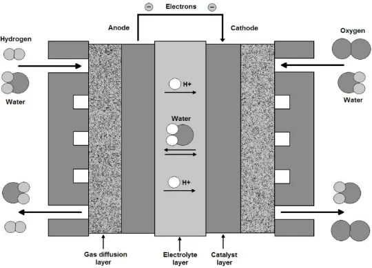
[image:3.596.169.439.360.555.2]Models play an important role in fuel cell development. PEM fuel cells use hydrogen as fuel and air as oxidizer. In PEMFC stack oxygen and hydrogen are consumed, and water and heat are generated. Humidification system is used to maintain hydration of the polymer membrane and to balance consumed water in the system.
Figure 1. The basic PEM fuel cell
The dynamic model for a PEM fuel cell is presented in this section to investigate current and gas humidity effects on ohmic, activation, and concentration overpotentials. In order to avoid model complexity, some simplifications will be considered including: first, the diffusion would be only in the x direction in a one-dimensional model, second, produced water is in the liquid phase because the temperature is constant and equal to 80C. Schematic overview of the fuel cell considered in this paper is shown in Fig. 1.
The voltage drop for a cell is dependent on the reactant partial pressure and membrane water content [16], the output voltage of a cell can be calculated, according to the Nernst’s equation and Ohm’s law:
ohm act conc
V E V V V (1)
in which, The thermodynamic potential of the cell or reversible voltage is given by Nernst equation can be written as:
2 2
2
ln H O
g H o P P R T E E nF P
(2)
where Vohm is ohmic overpotential, i.e., the ohmic voltage drop due to the resistance of proton
flow in the electrolyte. Vact is activation overpotential, that is, the voltage loss caused by the rate of
reactions on the surface of electrodes. Vconc is concentration overpotential, which is the voltage loss
because of the reduction in concentration gases or the transport of oxygen and hydrogen mass [17]. The operational variables were identified as [1]:
ohm ohm
V R j (3)
0
ln
g act
R T j V
nF j
(4)
1
1
ln
g conc
R T j V
nF j j
(5)
Total ohmic resistance is the sum of membrane, anode, and cathode resistances, i.e.
ohm m A C
R R R R . Their state equations have been derived in Ref. [4] as:
22 exp 2 A H g A H dJ KR T dE Kt
dt nFJ dt (6)
2 2 A H A ohm m H ohm dJ dV dR nFJ nFR
dt dt dt (7)
Activation overpotential is the required voltage loss to vanquish the energy barrier for doing the electrochemical reaction:
2 2
2
2 2
0
2 ln( )
A A H H act act A dl H g dl
n F J nFJ
dV
V
dt nFJ C
R TC j
(8)
Concentration loss mainly occurs at high output currents. Concentration loss originates from the intrinsic resistance of materials to charge flow.
2 2
2
2 2
1
1
2 ln( )
A A
H H
conc
act dl
g dl A
H
n F J nFJ
dV V j dt C R TC j nFJ (9)
Humidity includes two terms that they are in anode and cathode. XH O2 is the water mole
fraction, that is, the ratio of water diffusion flux to hydrogen and oxygen diffusion flux in the anode
2 2
2
H O
A A A
H O H
X J J and the cathode
2 2
2
H O
C C C
H O O
X J J . The state space model consists of these four nonlinear equations, i.e. Eq. (6, 7, 8, 9) which have the three inputs
2 A H J , 2 H O A
X , and
2
H O
C
X . Four state variables are E, Vohm , Vact, and Vconc. The output of the state space model is the fuel cell voltage V in
Eq. (1).
In order to use a single input-single output (SISO) controller, the PEM fuel cell model should be transferred into a SISO plant by correlating
2
H O
A X and
2
H O
C
X with two weight gains. Consequently, the controller output is weighted by gains of 1 and 0.43 and the result is fed into
2
H O
A X and
2
H O
C
X ,
respectively. The reason for choosing a smaller gain for
2
H O
C
X is the excessive sensitivity of the PEM fuel cell to the cathode water mole fraction [12].
In this paper, the output voltage is controlled with adjusting the mean membrane humidification rate . is used as input control because of Rm is not constant in Eq. (7) and it is related to water
activity aw. Thus Vohmis changed withand the output voltage is controlled with. The Eq. (10) shows
the relationship between andRm:
0
1 Lm
m
dx R
A x
(10)
such a way to satisfy humidification constraints. As the second, the cell current density should be maintained between the exchange and the limit current densities, i.e. j0 j j1.
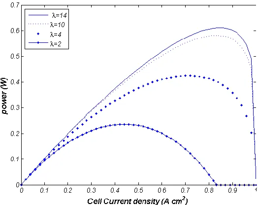
Power versus cell current density when is 2, 4, 10, and 14 are shown in Fig. 2. As it is shown in this Figure the maximum power is achieved when 14 and j0.85A and also, in maximum power
[image:6.596.163.425.235.443.2]the output voltage isV0.7274. According to Ref. [12], the cell voltage increases by humidifying the membrane when the value of the current density is constant; as a result, the ohmic and concentration overpotentials are decreased by humidification. When the changes apply to PEMFC, duo to ensure the system stability the setpoint must be 0.5V.
Figure 2. power versus cell current density when is 2, 4, 10, and 14
3. CONTROLLER DESIGN AND SIMULATION RESULTS
Neural networks are employed as a successful approach for identification and control of nonlinear systems [21]. Neural networks are also known by their swiftness of response and robustness. The most successful topology for nonlinear system control is Recurrent Neural Network (RNN). The RNN uses feedback in modeling and controlling nonlinear structures leading to a well performing control function [22]. For controlling with neural networks, there are two steps typically. The first is the system identification and the second is control design. In the former, a model of a dynamic system is developed based on the input and output signals from the system. Finally, the neural network plant model is employed to design or train the controller.
GAs act on a set of (artificial) chromosomes, which are string of numbers, generally sequences of binary digits 0 and 1. If the objective function of the optimization has many arguments (typically called control factors or decision variables), each string is partitioned in as many substrings of assigned lengths, one for each argument and, correspondingly, we say that each chromosome is partitioned in (artificial) genes. The genes constitute the so called genotype of chromosome and the substrings, when decoded in real numbers, constitute its phenotype. When the objective function is evaluated in a set of values of the control factors of chromosome, its value is called the fitness of chromosome. Thus, each chromosome gives rise to a exam solution to the problem in a set of values of its control factors. The GA search is be done by constructing a consecutive of populations of chromosomes the individuals of each population being the children of those of the previous population and the parents of those of consecutive population.
[image:7.596.159.431.406.611.2]The initial population is generated by randomly sampling the bits of all string. At each step, the new population gets by manipulating the strings of the old population in order to arrive at afresh population characterized by an increased mean fitness. This sequence continues until termination criterion is achieved. As for the natural selection, the string manipulation consists in selecting and mating pair of chromosomes in order to groom chromosomes of next population. This is done by repeatedly performing on the strings the four fundamental operations of reproduction, crossover, replacement and mutation, all based on random sampling [20].
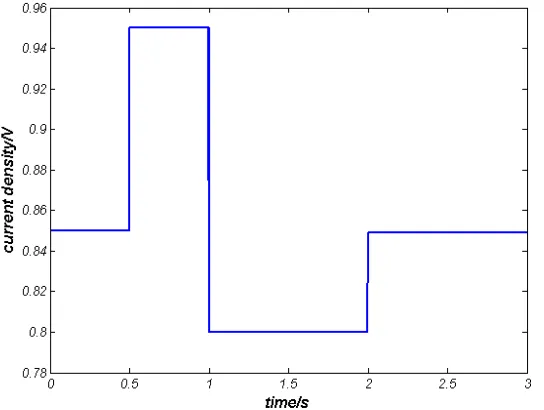
Figure 3. Stepwise current changes vs. time
In this paper, parameters of controller are obtained by a Genetic Algorithm with considering a population of 250 chromosomes, in which the chromosome has three genes, that considers three parametersKp,Ki,Kd, and the fitness function is:
2100
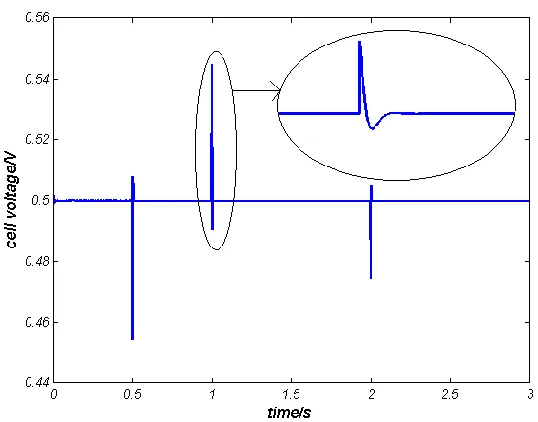
In order to investigate, how well the controller fixes the reference voltage at the set point, despite of the current density changes as shown in Fig. 3. Without controller the output voltage is shown in Fig.4.
After optimization, the parameters of controller are obtained as
5
188.957, 1.1739 10 , 0
p i d
[image:8.596.143.547.120.683.2]K K K . The results are shown in Fig. 5.
Figure 4. Cell voltage without controller
Figure 5. Cell voltage with PID-GENETIC
[image:8.596.168.437.450.661.2]
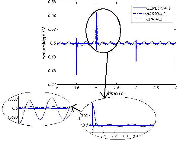
Figure 6. Cell voltage with PID-GENETIC and CHR-PID and NARMA-L2
The PEM fuel cell parameters like membrane resistance, usually is not constant with ageing, and it was necessary for the controller to keep the same performance. In order to investigate how well the controllers track the reference voltage when a change occurs in the plant parameters, a sinusoidal change in the anode resistance RA is applied to the plant while the current density changes in the same
way as in Fig. 3. It is assumed that a 30Hz frequency sinusoidal signal with the amplitude of 0.1RA is
added toRA. That is, RA 50 5 sin(230 )t . This sinusoidal signal actually simulates the ageing
process of PEMFC.
[image:9.596.151.444.495.729.2]
For having a scale to compare, a CHR-PID controller was designed. Study has been showed that the NARMA controller has a faster response than the CHR-PID controller. In this paper the optimal PID controller is designed based on Genetic Algorithm, has better response than CHR-PID and NARMA-L2 controller. As it is shown in Fig. 7, settling time and overshoot have been decreased and system converges to it’s setpoint fast, also the PID controller is more robust against uncertainty resulting from system membrane resistance and has less pendulous behavior.
4. CONCLUSION
This paper presented a dynamic model for water management in a PEM fuel cell. Derivatives of the dynamic equations for activation, concentration, and ohmic overpotentials were led to state-space model and was utilized to design a SISO plant for the PEM fuel cell. The designed NARMA-L2 controller, need to use identification of the PEM fuel cell plant. Then, the behavior of plant was trained and response of the NARMA-L2 controller was examined in the attendance of current changes and parameter variations, .In this method, the first step is system identification however, we don’t need it when algorithm genetic is used. The optimal controller based on Genetic controller, is designed and it has shown better response than neural network and classic control when changes occur in both of the current density and the plant parameters. In addition, the cell voltage was controlled, and the amount of water remained in the appropriate range. As a result, according to Ref. [12], the efficiency of the fuel cell membrane and life time is increased.
Appendix:
Table: Specifications Adopted For The Simulated Inverter
Symbol Description Unit Value
A Area 2
cm 1
E Electrochemical voltage at standard V 1.17
F Faraday constant 1
c mol 96485
0
j Exchange current density 2
Acm 104
1
j Limit current density 2
Acm 1
K Approximation input factor Dimensionless 10
dl
C Double layer capacitance mF 3.72
n Number of exchanged electrons Dimensionless 2
A in
P Anode pressure Atm 3
C in
P Cathode pressure Atm 3
g
R Gas constant 1 1
J mol K 8.314
a
R Anode resistance m 50
c
R Cathode resistance m 50
T Cell temperature K 353
References
1. C. Spiegel, PEM fuel cell modeling and simulation Using MATLAB, first ed., Elsevier, Burlington, 2008.
2. C. Kunusch, A. Husar, RF. Puleston, MA. Mayosky, More JJ., International Journal Hydrogen Energy, 33( 2008)3581-7.
3. H. Gorgun., International Journal Hydrogen Energy , 31(2006)29-38.
4. A. Haddad, R. Bouyekhf, A.E. Moudni, International Journal of Hydrogen Energy, 33 (2008) 6239-6252.
5. M. Tekin, D. Hissel, MC. Pera, JM. Kauffmann, Journal Power Sources, 156 (2006)57-63. 6. H. SR, L. CY, Wu CC, Yang SJ., International Journal Hydrogen Energy, 33 (2008)5205-17. 7. D. Chu, R.Z. Jiang, Journal Power Sources, 83 (1–2) (1999) 128–133.
8. O. Tatsuhiro, Journal Electroanal. Chem, 465 (1999) 1–17.
9. F. Wolfgang, R. Stephane, D. Bernard, IEEE Trans, Journal Power Electrons, 19 (5) (2004) 1234– 1241.
10.H. Abtahi, A. Zilouchian, A. Saenqrung, in: IEEE International Conference on Systems, Man and Cybernetics, (2005) 3486–3490.
11.L. Zhang, M. Pan, S. Quan, Journal Power Sources, 189(2008) 322–329. 12.M. Sedighzade, K. fathian, International Journal of Energy Research, (2011)
13.J.T. Pukrushpan, A.G. Stefanopoulou, H. Peng, Springer- Verlag, London, 2004, pp. 31–53. 14.F. Buchi, S. Srinivasan, Journal Electrochem. Soc., 144 (8) (1997) 2767– 2772.
15.M. Guerra, M., Zio, Z., Cadini, F, Annals of Nuclear Energy, 32(5) (2005) 712-728. 16.T.V. Nguyen, R.E. White, Journal Electrochem. Soc., 140 (1993) 2178–2186. 17.B. Gou, W.K. Na, B. Diong, Boca Raton, FL, (2010).
18.R.O. Hayre, S. Cha, W. Colella, F. Prinz, John Wiley and Sons, New York, (2006). 19.F. Barbir, PEM fuel cells, Springer, London, 2006.
20.D. Goldberg, Addison-Wesley Publishing Company, (1989). 21.MATLAB7, Mathematics, Mathworks Inc.