International Journal of
ELECTROCHEMICAL
SCIENCE
www.electrochemsci.org
Corrosion Performance of a Novel NiAl-Cu Intermetallic HVOF
Protective Coating Part I: Low Temperature Corrosion in 0.5 M
H
2SO
4.
E.F.Díaz1,3
, S. Serna1, J. Porcayo-Calderon2, C. Cuevas1, A. Torres-Islas3, A. Molina1 and J. Colin3,*
1 Centro de Investigación en Ingeniería y Ciencias Aplicadas -UAEM, Av. Universidad 1001,
Chamilpa 62209, Cuernavaca Morelos, Mexico
2 Instituto de Investigaciones Eléctricas, Reforma 113,Palmira 62490, Cuernavaca, Morelos, México. 3 Facultad de Ciencias Químicas e Ingeniería, Programa Educativo de Ingeniería Mecánica - UAEM,
Av. Universidad 1001,Chamilpa 62209, Cuernavaca, Morelos, México.
*
E-mail: [email protected]
Received: 6 March 2013 / Accepted: 12 April 2013 / Published: 1 May 2013
In this study the NiAl system macro-alloyed with Cu was used as a protective coating in an Inconel 600 alloy and X52 steel at low temperature for studying the corrosion conditions due to the “dew point corrosion” phenomena which produce sulfuric acid in fuel oil plants boilers. Conventional DC electrochemical test such as polarization curves and linear polarization resistance were compared with corrosion results obtained by the electrochemical noise (EN) technique. The results show that the NiAlCu coating protect well both alloys and is a very good option for against the dew point corrosion. However the steel coated protection do not reach the levels obtained for the coated Inconel 600 alloy, furthermore the coated Inconel 600 alloy seems to resist better the acidic corrosion environment. The EN techniques shows similar results and increase the knowledge of the corrosion of the coated and uncoated alloys showing corrosion mechanisms and performance, as this technique was used to monitor the corrosion of the studied alloys over time. The Rn and Rp values show some discrepancy
but have the same corrosion resistant sequence of the alloys under study proving their equivalence. Further deeper analysis was proposed to do in a subsequent paper corresponding to the EN data analysis.
Keywords: NiAl, NiAlCu, Intermetallic coatings, HVOF Thermal Spray, Corrosion coatings.
1. INTRODUCTION
manufactured practically in any required shape. Unfortunately, their oxides evolved under oxidant environments are not quite protective for applications above 500°C. However, the addition of other elements in suitable amounts (Cr, Al and Si) to their chemical compositions, have been improved their corrosion resistance to more elevated temperatures by the development of more stable oxide layers such as Cr2O3, Al2O3, and sometimes, SiO2. These oxides acts as shield to corrosion owing to their low
growth surface velocities [1, 2, 3].
On the other hand along the past 30 years several investigations have been demonstrated that is impossible to develop ideal oxide layers, and there are susceptible to failure at elevated temperature by fracture and crusting. In some cases, these oxides could be reformed maintaining corrosion protection. However, if chromium, aluminum and/or silicon were depleted in the iron, nickel or cobalt base alloys, less protective oxides would be formed, leading to a much more less corrosion protection. Because of these, coatings has been developed that could assure larger service lives and performance as those expected for the mentioned alloys [4, 5]. The coatings produced for satisfactorily corrosion resistance, are based on their reactive products formed on the alloys surfaces, for example, the Al2O3, Cr2O3
compounds can inhibit further corrosion reactions between the coating surface and the corrosive environment.
Traditionally, the most important coating systems for high temperature corrosion protection can be divided, based on its formation procedure, in two basic groups [1-6]: coatings by diffusion, that compile intermetallic compounds, generally aluminates, that are applied mostly by chemical vapor deposition (CVD) controlled by diffusion mechanisms, overload coatings, these methods deposit metallic alloys and ceramics compounds by thermal projection (flame spraying, electric arc, plasma, etc.) or physical vapor deposition (PVD) methods. Nevertheless such coatings could be applied for ambient temperature service and they are not limited to high temperature applications. For low temperature purposes these coatings could have better performances even in alloys that not develop protective oxides such as in Fe-C-Mn steels. Their application would depend principally on the relation material application protective-cost-benefit.
At the beginning of the 90s decade in the past century, intermetallic compounds have emerged as materials with vast potential for application in a wide range of technologically areas [7]. The relevance of intermetallics especially aluminides stems from their many attractive properties, such as high oxidation and corrosion resistance and relatively low densities, combined with their ability to retain strength and stiffness at elevated temperatures [8, 9]. Many investigations in intermetallics have been done on the aluminides principally in the Ni–Al system [10]. The two aluminides of significance in the Ni–Al system are Ni3Al and NiAl. Because of its low density, high melting temperature, good
alloying NiAl intermetallic compound with Cu and Fe, could lead to NiAl ductility as high as 6% and 12% in tensile test [18]. In addition, it was reported that microstructural control through the processing (i.e. rapid solidification, mechanical alloying and thermomechanical treatments) can improve their ductility [19-22]. However, this system is not yet available for structural applications.
Kim et al [23], through RF magnetron sputtering used NiAl coatings for deposition on Ni3Al
thin foils for oxidation resistance. In their study, insufficient coating thickness could induce rapid Al depletion in the NiAl coating layer. However, Kim et al., reported that the addition of 3 at. % Ti was very effective in retarding atomic diffusion and Al depletion in the coating layer. Although the interest of nickel aluminates is for high temperature applications, some room temperature applications are being discovered, for example as biomaterials or seawater environments applications [24]. Some other technological important application is in fossil (fuel oil) plants boilers, where stainless steels and nickel superalloys, among others, are commonly used [25, 26]. β-NiAl phase, an important intermetallic compound in Ni-Al systems, together with '-Ni3Al phase, has been used as a coating
material for Ni-base superalloys, because of its excellent oxidation resistance. However, conditions, in which the fuel oil combustion takes place, play a key role in the boiler materials performance. High air excess during the combustion process enhances high temperature oxidation of super-heaters and re-heaters, accelerated by vanadium and sulfur compounds. This condition also increases the generation of SO3 and hence the corrosion by sulfuric acid in the low temperature zone of the boiler [27]. The
aqueous, low temperature corrosion resistance of NiAl-Cu for its use as a coating material is of concern for high temperature applications because these materials (stainless steels and nickel superalloys) will not always be at high operating temperatures, since transients like start-ups and shutdowns in fossil plants occur. As already mentioned, sulfur is present and, in these transients, condensation of sulfuric acid occurs producing the so called “dew point corrosion” which could lead to catastrophic failures during service.
The goal of the present work is to investigate a novel no structural application of the NiAl system macro-alloyed with Cu as a protective coating applied by High Velocity Oxygen Fuel (HVOF) thermal spraying technique on a nickel base alloy. Its performance was evaluated in a 0.5 M sulfuric acid at low temperature, for comparison a not protective layer oxide producer alloy (Fe-C-Mn steel) was also coated with the NiAl-Cu and evaluated.
2. EXPERIMENTAL PROCEDURE
2.1 Materials and Corrosion Media
mounted into epoxy resin leading the coated surface free in the case of coated substrates and a free rough surface free for the uncoated specimens.
Surface morphology and cross-section studies of the coatings were carried out using a scanning electron microscope (SEM). The surface and cross sectional chemical compositions were analyzed by energy dispersive X-ray spectroscopy (EDS).
Table 1 shows the NiAlCu coating chemical composition.
Table1. Chemical analysis by EDS registered in the samples.
Substrate Elemental Composition of the coating (wt. %)
Cu Al Ni
Inconel 600 Alloy 15 ± 1.3 35 ± 1.02 Bal.
FeCMn steel 15 ± 0.8 35 ± 1.1 Bal.
Structural investigations were conducted by XRD method using a Philips diffractometer (X'Pert model) with Cu Kα radiation (U=40 kV, I=20 mA). Diffraction patterns were recorded in the 2θ range from 20° to 150°. Phase identification was carried out on the base of ICDD card standards (2000).
The corrosion media was prepared from analytical grade reagents and deionized water to obtain a 0.5 M sulfuric acid (H2SO4) aqueous solution.
2.2 Electrochemical Test
Electrochemical techniques such as Polarization Curves (PCs) and Electrochemical Noise (EN) were used to characterize the corrosion performance of the NiAl-Cu coating system and the bare Inconel 600 alloy and X52 steel surfaces at room temperature (25±2 ◦C) in the 0.5 M H2SO4 solution.
Electrochemical experiments were performed using an ACM Instruments potentiostat controlled by a personal computer using all the mounted epoxy resin alloys specimens, coated and uncoated as working electrodes. These specimens have suitable attached by spot welding a nichromel (Ni20Cr) wire for electrical contact.
PCs were obtained by varying the applied potential from −300mV to + 600 mV respect to the Ecorr, at a scan rate of 60 mV/s. Before the experiments, the Ecorr value was measured for approximately
30 min, until it was stable. All potentials were measured using a saturated calomel electrode (SCE) as reference electrode. The counter electrode was a graphite rod. Corrosion rates were calculated in terms of the corrosion current, Icorr, by using linear polarization resistance (LPR) curves. This operation was
performed by polarizing the specimen from +10 to −10mV, with respect to Ecorr, at a scan rate of 1
mV/s to get the polarization resistance, Rp. icorr values were calculated using the Stearn–Geary equation
Where ba and bc are the anodic and cathodic slopes obtained from the polarization curves.
Corrosion rates values, in mm/year, were calculated using Faraday’s law.
In order to determine the pitting stability tendency the electrochemical noise technique was applied. In this case, the current and voltage fluctuations between two identical electrodes were recorded at the free corrosion potential, Ecorr vs. SCE (Saturated Calomel Electrode). For these
measurements, a zero resistance ammeter (ZRA) from ACM Instruments was used controlled by a desktop computer taking current and voltage noise readings in blocks of 1024 points at 1 s interval. From the unprocessed EN data their trend was removed due to instabilities in the working electrodes during the test period as established by assuming that the drift of potential V and current I follow linear expressions such as in Mansfield et al work [30]. If this is not carried out considerable deviation of the calculated noise resistance (Rn) is obtained when calculated from:
(2)
Where v is the potential standard deviation and I is the current standard deviation of the
experimental noise data.
After the electrochemical experiments, the specimens were cleaned to be observed in the scanning electron microscope (SEM) and micro-chemical analysis of the corroded specimens were analyzed using energy dispersive spectroscopy (EDS).
3. RESULTS
[image:5.596.173.399.532.741.2]3.1 SEM Characterization
[image:6.596.157.511.218.398.2]
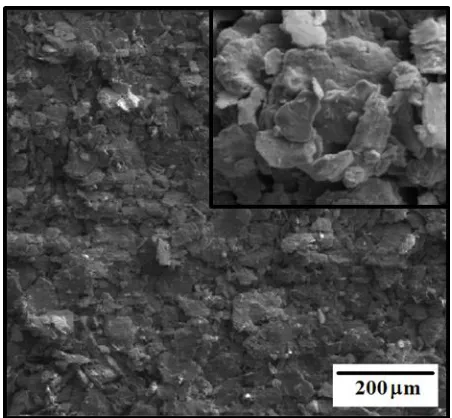
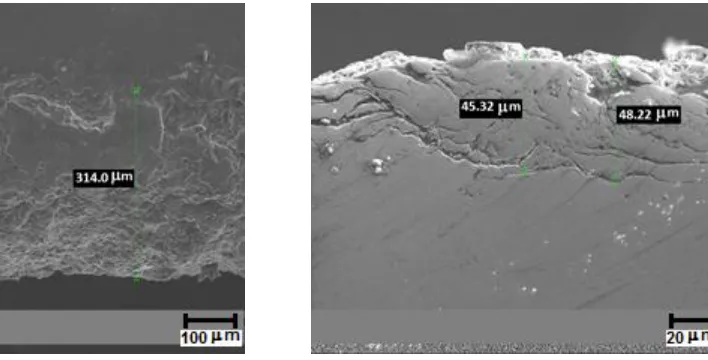
Figures 1 and 2, shows the surface and cross section morphologies respectively for the NiAlCu HVOF coatings. Figure 1 illustrates a like-flakes grain type surface structure with a few tiny voids randomly distributed. The box shows at higher magnifications the formation of a thin oxide layer over the flakes as a common characteristic of the HVOF process. Figure 2 shows cross-sectional micrographs for both alloys spray deposited NiAlCu structure and alloy interphase. Figure 2a) shows that the coating thickness was wider for Inconel 600 alloy than for the steel as shown in figure 2b) with 48m and 320 m respectively.
Figure 2. Show the morphologies of the cross section of the NiAlCu coating for, a) X52 steel and b) Inconel 600 Alloy.
3.2 Electrochemical Tests 3.2.1 Polarization Curves
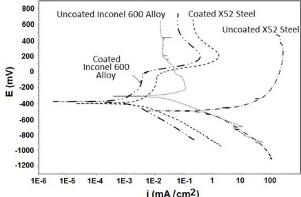
Figure 3 shows the polarization curves of the different materials tested. Clearly shows that the X52 steel has the worst behavior among the other materials and coated materials tested. Their Ecorr and
icorr values denotes that this alloy was the most susceptible to be corroded in the test solution.
Furthermore as showed by their anodic curve the X52 Steel corrodes until an over-potential of approximately 500 mV was reached showing some tendency to get passivated. On the other hand, Inconel 600 alloy shows passivation along all the over-potential range tested. This denotes auto-protection to the corrosive solution and an icorr value almost two magnitude orders below the icorr value
Figure 3. Polarization Curves of coated and uncoated alloys under corrosion study in aqueous sulphuric acid solution.
A summary of the electrochemical parameters, including the corrosion potential, Ecorr,
corrosion current density, Icorr, anodic and cathodic Tafel slopes, ba and bc, passivation potential, Epass,
[image:7.596.76.513.79.366.2]passivation current density, Ipass, and pitting potential, Epit, is given in Table 2.
Table 2. Electrochemical parameters obtained after the tests
Material Ecorr
(mV)
Icorr
(mA/cm2)
ba bc Epass
(mV)
Inconel 600 Alloy -317 3.08 x 10⁻² 155 149 -213
X-52 Steel -501 3.02 122 154 78
CoatedInconel 600 Alloy -381 1.78 x 10⁻³ 160 219 224
Coated X-52 Steel -408 4.80 x 10⁻³ 194 200 161
3.2.2 Polarization Resistance
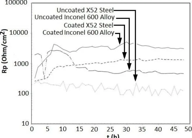
Figure 4 shows the LPR results from the coated and uncoated alloys, in agreement with the results showed in Figure 3, the coated Inconel Alloy 600 shows a major corrosion protection tendency among the other alloys and coatings presenting the highest Rp peak value of 5,210 cm2. Also, the
uncoated 52 steel shows the lowest Rp values denoting as in figure 2 the worst corrosion performance
over the time tested. Uncoated Inconel 600 Alloy shows at initial times more corrosion resistance, however, as test time continues the alloy 600 tends to lower their corrosion resistance. The maximum
peak Rp value for the coated X52 steel was 1,360cm2 that is obviously lower than the Rp value for
the coated Inconel 600 Alloy. But, as in Figure 3 the protection gap between the coated and uncoated X52 Steel Rp values is higher compared with the gap between the coated and uncoated Inconel 600
alloy Rp values denoting a higher degree of protection by the NiAl-Cu coating for the steel.
Figure 4. Polarization resistance of the uncoated and coated materials immersed in 0.5 M H2SO4
solution
In general, it is observed that coated materials were the only ones which showed a tendency to decrease its corrosion rate on the immersion time. This indicates that the NiAl-Cu layer could maintain after a certain immersion time a passive film of corrosion products.
3.2.3 Electrochemical Noise (EN)
[image:8.596.137.458.265.495.2]raw data in many electrochemical techniques. In addition, V and I will be changed [32] which will affect the computed value Rn =V/I. It was not possible to obtain mechanistic information from such raw data without the use of appropriate trend removal techniques. The trends in the experimental EN data were removed by assuming that the drift of potential V and current I follow linear expressions such as [30]:
and
From Eq. (3a and b) it follows that a plot of the potential fluctuations V versus the current fluctuations I should result in a straight line with a slope of a/b:
I = 0 will be observed for:
The current noise fluctuations in the time domain with trend removed for the coated and uncoated specimens under study are shown in figures 4 to 7, after being immersed in 0.5 M H2SO4
solution during 2, 16, 32, and 48 hours. These fluctuation readings were taken after a few minutes of immersion showing anodic and cathodic transients with varied intensities and frequencies. The aim of using EN signals was to determine general relations between the characteristics of electrochemical noise and corrosion rates and types. The metals in various electrolytes corroded uniformly and locally, or intensively, or not at all. The correlation between the shapes of the electrochemical current signals or transients and the types of corrosion were described as follows.
0 200 400 600 800 1000
-0.0004 0.0000 0.0004 I(A ) Time(s) a)
0 200 400 600 800 1000 -0.0004 0.0000 0.0004 I(A ) Time(s) b)
0 200 400 600 800 1000
-0.0004 0.0000 0.0004 I(A ) Time(s) c)
[image:10.596.106.473.85.376.2]0 200 400 600 800 1000 -0.0004 0.0000 0.0004 I(A ) Time(s) d)
[image:10.596.248.475.618.760.2]Figure 5. Noise current transients over time of uncoated Inconel 600 Alloy after immersed times of a) 2h, b)16h, c) 32h, d) 48h in 0.5M H2SO4 solution.
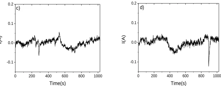
Figure 6 shows the current time signals of the plain X52 Steel, a clear difference between the current signal time series of the Inconel 600 Alloy is the amplitude difference, compared with X52 steel current amplitude three orders of magnitude could be observed. In this case the steel tends to form a passive film or at least protective corrosion products after uniform corrosion over their surface after the 2 hours. Instead at 4 hours of immersion the sulfur cause localized rupture of the film showing pitting corrosion. As a result it could be seen diverse current transients when pits start, growth and get repassivated. However, after 32 and 48 hours the system seems to be stabilized showing more uniform transients with lesser tall picks indicating a tendency for uniform corrosion.
0 200 400 600 800 1000
-0.1 0.0 0.1 0.2 I(A ) Time(s) a)
0 200 400 600 800 1000
0 200 400 600 800 1000 -0.1
0.0 0.1 0.2
I(A
)
Time(s) c)
0 200 400 600 800 1000
-0.1 0.0 0.1 0.2
I(A
)
Time(s) d)
Figure 6. Noise current transients over time of uncoatedX52 Steel after immersed times of a) 2h, b)16h, c) 32h, d) 48h in 0.5M H2SO4 solution
Regarding the coated alloys Inconel 600 + NiAlCu, corrosion behavior was presented on figure 7 at all immersion times. After 2 hours the system seems to be very stable but again after 500 s present a perturbation of the current time signal but in this case was not a quick deep transient. The form of the transient indicates possible some kind of crevice corrosion formed at some point of the coated surface indicating a possible severe damage of the coating more extended than a pit size. However the next transients shows a healing and less pitting behavior as time passes, reaching a very uniform almost free of localized corrosion surface after 48 hours of the test. An interesting point is that the amplitude of the coated alloy 600 present a difference with the uncoated alloy of one order of magnitude showing possible more corrosion activity of the coated surface, but finally as shown by their corrosion rates a better protection. Contrary to the uncoated steel in Figure 5 a), after 2hours of immersion we could see on figure 8 a) that the coating changes dramatically their corrosion behavior. It seems a more active decreasing the activity at the very beginning presenting some pitting to a very active zone after 600 s showing a higher pitting behavior. However this activity is seen at two orders of magnitude lesser in the current amplitude compared to Figure 5a meaning a much more corrosion rate. The scenario on figure 8 b) showed that the coating possibly lost their initial protection and present current transient as those presented for the uncoated steel very similar in shape and amplitude.
0 200 400 600 800 1000
-0.003 0.000 0.003
I(A
)
Time(s) a)
0 200 400 600 800 1000
-0.003 0.000 0.003
I(A
)
[image:11.596.103.481.84.232.2] [image:11.596.305.470.594.741.2]
0 200 400 600 800 1000 -0.003 0.000 0.003 I(A ) Time(s) C)
0 200 400 600 800 1000
-0.003 0.000 0.003 I(A ) Time(s) d)
Figure 7. Noise current transients over time of Inconel 600 Alloy coated with the NiAl+Cu intermetallic after immersed times of a) 2h, b)16h, c) 32h, d) 48h in 0.5M H2SO4 solution.
Nevertheless the coating seems to be rehabilitated developing passive film as indicated by Figure 8 c) and 8 d). Although the transient looks like the ones showed in 5 c) and 5 d) for the uncoated steel, their orders of magnitude respect the corrosion time signals amplitude is about one order lesser demonstrating that the coating serves to protect the steel. On the other hand more uniform pitting persists but at lower intensities presenting some extreme pitting cases as could be seen mostly in figure 8 d).
0 200 400 600 800 1000 -0.008 0.000 0.008 I(A ) Time(s) a)
0 200 400 600 800 1000 -0.1 0.0 0.1 0.2 I(A ) Time(s) b)
0 200 400 600 800 1000 -0.08 0.00 0.08 I(A ) Time(s) c)
[image:12.596.109.483.86.224.2]0 200 400 600 800 1000 -0.08 0.00 0.08 I(A ) Time(s) d)
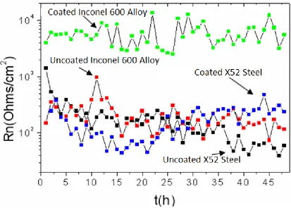
[image:12.596.101.479.434.698.2]In many applications the electrochemical noise resistance (Rn), determined as the standard deviation of the potential noise divided by the standard deviation of the current noise, has been found to be comparable to the linear polarization resistance (Rp), determined by LPR. However, Rn tends to be rather more variable than Rp, and it offers little advantage. It might be claimed that Rn require less complex measurement equipment, but this loses credibility with the appearance of low cost modern electronics. In order to obtain better agreement between Rn and Rp it is often necessary to collect EN data for long time periods. In general Rn is expected to agree with Rp only for systems with high corrosion rates for which the impedance spectrum has reached the dc limit within their frequency range (delta f ) [33].
The Noise resistance of the alloys and their respective coatings systems immersed in O.5 M H2SO4 solution were shown in Figure 9. It can be seen as presented by their Rp counterparts that the
more resistive to corrosion system was the presented by the Inconel 600 Alloy + NiAlCu coating as clearly shown by their Rn transients. This system presents much better resistant values almost two
orders of magnitude over their uncoated counterpart and the steel and steel coated systems. The coated steel present bigger Rn values than the bare steel showing a better corrosion behavior but although the
coating protect the steel the uncoated Inconel 600 Alloy present higher values.
Figure 9. Noise Resistance (Rn) data over time, after 48 hours of immersion in the 0.5 M H2SO4
solution.
[image:13.596.89.502.397.692.2]
time, this suggest that the coated and uncoated surfaces was continuously under activation corrosion conditions at the first hours of immersion. Later, a corrosion products passive film formed as indicated by the polarization curves previously presented protecting their surfaces in major or minor grade as already shown in figures 4 to 7.
On the other hand comparing Figure 4 and Figure 9 it can be seen that the Rp and Rn values
have a great concordance with the behavior showed in the polarization curves and their corrosion rates values. For example from table 2 we can see that the Icorr values for the Inconel 600 alloy coated with
the NiAlCu intermetallic are lower compared with the X52 uncoated steel values under the same test conditions.
4. DISCUSSION
4.1 Coated Materials
Figures 1 and 2 shows for both alloys superficial voids and cross sectional microscopic pores in their respective NiAlCu coatings which can be promoted due to the high velocity and turbulence of the impinging powder melts. However, these pores will potentially help in the prevention and blunting of any crack initiation or propagation, by forming bigger plastic zones at their rounded pore tips, this was more evident for the coated Inconel 600 Alloy. In the case of the surface small voids also can be assumed that arise from the Kirkendall effect due to diffusion of Al atoms from the Al rich NiAlCu coating to the Al lean substrate during their partial melting and re-solidification. Thus, the cross section pores could have in turn some influence to be originated or propagated from the Kirkendall superficial voids by the same Al atom diffusion mechanism. Since Al is essential for Al2O3 formation,
the Al coating depletion by diffusion can deteriorate its corrosion resistance. Nevertheless, the Kirkendall effect could be reduced or repressed by the Cu addition with respect to the solely NiAl alloy, thus showing the very tiny voids and pores as shown in Figure 1 and 2. This could be achieved by the Al substitution by some Cu atoms when added to the binary intermetallic NiAl. The different atomic ratio between aluminum and copper, greater size for Cu [18, 21, 22], can difficult Al diffusion within the NiAlCu lattice when partial re-solidification takes place. Kim et al [23] reported similar behavior adding Ti instead of Cu to the Ni-50Al system as a coating for Ni3Al thin foils in which the
coating thickness was restricted to less than 10 microns. The same effect was reported in the hydroxyapatite–zirconia composite coating system by Khor and co-workers [34]. In this case the coating porosity level decreased to a great extent with the incorporation of zirconium particles.
The like-flakes grain type superficial morphology shown in the box of Figure 1 could be the result of mechanical interlocking of NiAlCu-particles attributed to heavy plastic deformation upon a high degree of particle impact. This heavy impact could leads to fragmentation of re-solidifying particles and thus formation of large number of nucleation sites, which might causes higher extent of grain refinement in the deposit structure.
after partial/complete melting deposit on the substrates due to ejection from the HVOF nozzle gun at extremely high velocity. Therefore, the adhesion or bonding of particles in the substrates deposits was the result of two factors: The partial/complete melting and re-solidification of particles and the mechanical interlocking of particles attributed to heavy plastic deformation upon impact [35] as already mentioned.
4.2 Corrosion Performance
From the polarization curves and Rp results was obvious that the Inconel 600 Alloy have a
good corrosion resistance and its performance was greatly incremented by the NiAlCu coating. The X52 steel present high corrosion rates under the acid environment and the NiAlCu coating protected the steel surface but not reaching the protection levels and corrosion resistant observed by the bare alloy 600 surface and its coated surface. Such difference can be due to the thickness of the coating which is thinner than that of the Iconel 600 Alloy. As discussed in the previous section the NiAlCu coating shows a greater corrosion resistance due to the development of a protective alumina layer which seals its surface and prevents entry of sulfuric acid, also the Cu addition could improve the coating protection by reducing the Kirkendall effect. Due to the porous nature of the coating, it is possible that the acid can reach the coating-alloy interface but this can be passivated closing this pore over time. This was evidenced by the EN results discussed below that permit to elucidate corrosion and mechanisms behaviors. In addition, the physical phenomena occurring during their deposition leaves a homogeneous layered high dense structure with particle adhesion in the substrate deposit, this contributes to the coating protection ability in both alloys (Inconel 600 alloy and the X52 steel).
Once in the solution the corrosion resistance of the NiAl intermetallic is based upon the establishment of a passive layer composed of NiO and Al2O3. When Cu is added, Cu2O particles are
formed which starts to be incorporated into the external passive NiO and Al2O3 layers by substitution
of the Al2O3 particles since the Al contents in the corrosion products decrease. The incorporation of
Cu2O particles into the passive layer clearly increases the corrosion resistance of these oxides as
evidenced by their corresponding Polarization Curves showed in Figure 3.
The EN method has been studied by many research groups and implemented as a practical corrosion monitoring system [36]. Where EN does offer the prospect of significant benefits compared to LPR and other electrochemical techniques for studying corrosion is in the detection of localized corrosion. The simplest and more direct electrochemical noise analysis method is by examination of the electrochemical noise time series for identification of characteristic details of the particularly corrosion types.
lower than during uniform corrosion. Indeed, the visual detection of breaking and repassivation transients can be associated to localized corrosion such as crevice or pitting corrosion. The nucleation, growth, and death of metastable pits produce current transients with duration of the order of a few seconds. Metastable pits typically consist of a slow current rise followed by a sharp current fall (for stainless steel) or a moderate current rise followed by a slower fall (for carbon steel and aluminum alloys). For example, the type of corrosion showed by Figure 5 is clearly defined produced in the steel immerse in the acid solution. In this case the steel tends to form a passive film or at least protective corrosion products over their surface after the 2 hours, but at 4 hours of immersion the sulfur produce localized rupture of the film showing pitting corrosion. As a result it could be seen diverse current transients when pits start, growth and get repassivated, modifying the initial structure of the current time series as a function of immersion time. However, after 32 and 48 hours the system seems to be stabilized showing more uniform transients (more frequent current transients) with lesser tall picks indicating a tendency for uniform corrosion. Ought to the well defined structure of the current time series and the established relation between this time series and the physicochemical process associated, it was easy to obtain the corrosion behavior or mechanism of the corrosion system.
It is well known that electrochemical noise is similar to the noise in electronic devices; therefore, some authors have compared it to characteristic types of electronic noise (thermal, shot, and flicker noise) [37]. Thermal and shot noises are white, while the power-density spectrum (PSD) of flicker noise can be described by a function over a frequency interval. At low frequencies, such that individual metastable pitting events may be regarded as instantaneous, the shot noise analysis can be applied. This result has apparently provided a successful estimate of the pit dimensions for the pitting corrosion of Al [38], although further validation is required. Accordingly with our results in the uncoated X52 steel, this analysis assumes that essentially all of the corrosion current is associated with the metastable pitting. The use of
q
(charge on charge carrier) andƒ
n (mean frequency of chargeemission) has been successful in describing the behavior of steel in chloride/nitrite mixtures [39]. Both of these estimates were made using the variance divided by the bandwidth, rather than the preferable method of using the low frequency limit of the power density spectrum (PSD). Nevertheless in a second paper the shot noise analysis and the PSD method will be used for the analysis of the noise data presented for comparison of analysis and corroboration of results.
The Rn is obtained by dividing the standard deviation of potential by the standard deviation of
current. Several workers have analyzed the relationship between the Rn and the Rp [40], and some
claim to have proved that the two are equivalent. However, all of these analyses assume, either explicitly or implicitly, that the potential noise can be modeled as the action of the current noise on the metal-solution impedance, with the latter usually treated as the Rp, and they therefore effectively
assume that the Rn and Rp are equivalent. In this study the Rp values were similar to that for the Rn
values the only difference is that for Inconel 600 alloy coated the Rn values is one order of magnitude
higher than the reported by their Rp corresponding value. The sequence of the corrosion resistant was
Inconel 600 Alloy proved to be very resistant to the sulphuric acid solution, showing passivation that could be stable at higher potential levels as showed by their polarization curve. However the NiAlCu coating proves to protect more the Inconel 600 alloy surface under the same experimental conditions. Also, alloy 600 when coated, presents passivation but at higher potentials present film rupture and repassivation, the repassivation film seems to be more stable at least under the anodic potential range tested. X52 Steel shows poor corrosion resistance to the H2SO4 solution,
however, after steel was coated their corrosion resistant grows up considerably. The LPR test shows identical results over the elapsed test time, the NiAlCu coating effectively protects the alloy 600 and X52 steel from further corrosion presenting Rp stable values respectively.
The current time noise series allows knowing the surface corrosion behavior and localized corrosion mechanisms showed by coated and uncoated Inconel 600 alloy and X52 steel. The uncoated Inconel 600 alloy surface presents very low pitting corrosion that leads a stable white noise after 48 hours of corrosion monitoring. These results indicate surface passivation and almost null corrosion over its nude surface. The coating could present more active localized corrosion at its surface, including crevice corrosion, but exhibit also healing and pitting repassivation behaviors. This contributes to the higher protection as was evidenced by their corresponding LPR and polarization curves test. In the case of the coated and uncoated X52 steel substrate the behavior seem to be the same at least at the first hours of test monitoring. However the coated steel current noise transients after 16 hours present their corrosion current transient values one order of magnitude lower, nevertheless almost with the same corrosion current transient morphology as the uncoated steel.
The Cu addition prove to be a beneficial alloying element to the NiAl intermetallic, that combined with the HVOF thermal coating process seals pores, and maintain a rough density surface over the alloy 600 and X52 steel substrates. When the NiAlCu coating is in contact with the corrosion solution the Cu addition could help to the protection of Inconel 600 alloy and X52 steel, due to the formation of very stable Cu2O corrosion particles. This in addition to the protective film based on NiO
and Al2O3 oxides form a very protecting repassivating coating.
ACKNOWLEDGEMENTS
The authors acknowledge the support of Programa de Mejoramiento del Profesorado by the postdoctoral scholarship given to E. Moronatti for the development of the project
PROMEP/103.5/10/4453 under the direction of J. Colin as a member of the Academic Group “Caracterización de Materiales Metálicos” in the UAEM for consolidation purposes. In Addition, we would like to thank to Ing. J. A. Valerio Carvajal of the FCQeI-UAEM for the technical support provided
References
2. F. Fitzer, and J. Schlichting, Coatings containing chromium, aluminium, and silicon for high temperature alloys, High Temperature Corrosion, Editor: R. A. Rapp, March 2-6, 1981, San Diego California, NACE, HOUSTON, TX, pp. 604-614.
3. F. H. Stott, Materials Science and Technology, 5, 8, (1989) pp. 734-740 4. T.N. Rhys-Jones, Corrosion Science, 29, 6, (1989), pp. 623-646
5. J, Stringer, Materials Science and Engineering, 87, (1987), pp. 1-10
6. A. McMinn, Coatings technology for hot components of industrial combustion turbines: A review of the state of the art, Report EPRI AP-5078 prepared by Southwest Research Institute, 1987. 7. R. Darolia, J. Met.43, 3, (1991) pp. 44–49
8. E. P. Busso, F. A. Mcclintock, Acta Metall. Mater.42, (1994), pp. 3263–3275 9. R. Jayaram, M. K. Miller, Acta. Metall. Mater.42, (1994), pp. 1561–1572
10.R. D. Field, D. F. Lahrman, R. Darolia, Acta Metall. Mater.39, (1991), pp. 2951–2959 11.G. K. Dey, J. A. Sekhar, Metall. Mater. Trans.B28, (1997), p. 905
12.G. K. Dey, J. A. Sekhar, Metall. Mater. Trans.B30, (1999), pp. 171–188
13.R. D. Field, D. F. Lahrman, R. Darolia, Acta. Metall. Mater.39, (1991), pp. 2961–2969 14.R. D. Noebe, R. R. Bowman, M. V. Nathal, Int. Mater. Rev.38, (1993), pp. 193–232,
15.R. D. Noebe, R. R. Bowman, M. V. Nathal, Physical and mechanical metallurgy of NiAl. Physical metallurgy and processing of intermetallic compounds (eds) N S Stoloff, V K Sikka (New Delhi: CBS) 1997 pp. 212–296
16.V. I. Levit, I. A. Bul, J. Hu, M. J. Kaufmann, Scr. Mater.34, (1996), pp. 1925–1930 17.R. Darolia, D. Lahrman, R. Field, Scr. Metall. Mater.26, (1992), pp. 1007–1012
18.J. Colin, C. Gonzalez, R. Herrera, J.A. Juarez Islas, J. Mater. Eng. Perform. 11 (2002) 487–491 19.S.H. Song, S.H. Kim, M.H. Oh, J.H. Lee, D.M. Wee, Intermetallics 13 (2005) 203–210, 20.A. Misra, R. Gibala, R.D. Noebe, Intermetallics 9 (2001) 971
21.J. Colín, S. Serna, B. Campillo, O. Flores, J. Juárez-Islas, Intermetallics, 16, 7, (2008), pp 847-853, 22.J. Colín, S. Serna, B. Campillo, R.A. Rodríguez, J. Juárez-Islas, Journal of Alloys and Compounds,
489, 1, 2010, pp 26-29
23.S.H. Kim, M.H. Oh, K. Kishida, T. Hirano, D.M. wee, Intermetallics, 13, (2005), pp 129-136 24.M.C. Garcia-Alonso, M.F. Lopez, M.L. Escudero, J.L. Gonzalez-Carrasco,D.G. Morris,
Intermetallics 7 (1999) 185.
25.C.L. Zeng, P.Y. Guo, W.T. Wu, Electrochim. Acta 49 (2004) 1445. 26.W.H. Lee, R.Y. Lin, Mater. Chem. Phys. 77 (2002) 86.
27.J. Castrejon, S. Serna, A. Wong-Moreno, A. Fragiel, D. Lopez-Lopez, Materials Science and Engineering A 415 (2006) 118–125
28.C.D. Arrieta-Gonzalez, J. Porcayo-Calderon, V.M. Salinas-Bravo, J.G. Chacon-Nava, J.G.
Gonzalez-Rodriguez, International Journal of Electrochemical Science, Vol 6, No 8 (2011) 3644 – 3655.
29.M. Stearn, A.L. Geary, J. Electrochem. Soc. 105 (1958) p. 638 30.F. Mansfeld, Z. Sun, C.H. Hsu, A. Nagiub, Corr. Sci. 43 (2001) 341. 31.Z. Zon, Corrosion 55 (1999) p. 915
32.F. Huet, U. Bertocci, C. Gabrielli, M. Keddam, Proceedings of the Topical Research Symposium, CORROSION/97, NACE, 1997, p. 11.9
33.C.C. Lee, F. Mansfeld, Corr. Sci. 40 (1998) 959.
34.H. Li, K.A. Khor, R. Kumar, P. Cheang, Surf. Coat. Technol. 182 (2004) 227
35.P. Fauchais, A. Vardelle, B. Dussoubs, J. Thermal Spray Technol. 10, (2001) p. 44, H. Herman, S. Sampath, Metallurgical and Protective Coatings, Chapman and Hall, London, 1996
36.H. A. A. Al-Mazeedi, R. A. Cottis, Electrochemica Acta 49 (2004) p. 2787. 37.M. Hashimoto, S. Miyajima, T. Murata, Corros. Sci. 33 (1992): p. 917. 38.R.A. Cottis, S. Turgoose, Mater. Sci. Forum 192-194, 2 (1995): p. 663-672.