This is a repository copy of
Successive interference cancellation schemes for
time-reversal space-time block codes
.
White Rose Research Online URL for this paper:
http://eprints.whiterose.ac.uk/3692/
Article:
Song, L-Y., de Lamare, R.C. and Burr, A.G. orcid.org/0000-0001-6435-3962 (2008)
Successive interference cancellation schemes for time-reversal space-time block codes.
IEEE Transactions on Vehicular Technology. pp. 642-648. ISSN 0018-9545
https://doi.org/10.1109/TVT.2007.905602
[email protected]
https://eprints.whiterose.ac.uk/
Reuse
Items deposited in White Rose Research Online are protected by copyright, with all rights reserved unless
indicated otherwise. They may be downloaded and/or printed for private study, or other acts as permitted by
national copyright laws. The publisher or other rights holders may allow further reproduction and re-use of
the full text version. This is indicated by the licence information on the White Rose Research Online record
for the item.
Takedown
If you consider content in White Rose Research Online to be in breach of UK law, please notify us by
White Rose Research Online
Universities of Leeds, Sheffield and York
http://eprints.whiterose.ac.uk/
White Rose Research Online URL for this paper:
http://eprints.whiterose.ac.uk/3692/
Published paper
Song, L.Y., de Lamare, R.C. and Burr, A.G. (2008) Successive interference
cancellation schemes for time-reversal space-time block codes, IEEE
Transactions on Vehicular Technology, Volume 57 (1), 642 - 648.
642 IEEE TRANSACTIONS ON VEHICULAR TECHNOLOGY, VOL. 57, NO. 1, JANUARY 2008
Successive Interference Cancellation Schemes for Time-Reversal Space-Time Block Codes
Lingyang Song,Student Member, IEEE, Rodrigo C. de Lamare,Member, IEEE, and
Alister G. Burr,Member, IEEE
Abstract—In this paper, we propose two simple signal detectors that are based on successive interference cancellation (SIC) for time-reversal space-time block codes to combat intersymbol interference in frequency-selective fading environments. The main idea is to treat undetected symbols and noise together as Gaussian noise with matching mean and variance and use the already-detected symbols to help current signal recovery. The first scheme is a simple SIC signal detector whose ordering is based on the channel powers. The second proposed SIC scheme, which is denoted parallel arbitrated SIC (PA-SIC), is a structure that concatenates in paral-lel a certain number of SIC detectors with different ordering sequences and then combines the soft output of each individual SIC to achieve performance gains. For the proposed PA-SIC, we describe the optimal or-dering algorithm as a combinatorial problem and present a low-complexity ordering technique for signal decoding. Simulations show that the new schemes can provide a performance that is very close to maximum-likelihood sequence estimation (MLSE) decoding under time-invariant conditions. Results for frequency-selective and doubly selective fading channels show that the proposed schemes significantly outperform the conventional minimum mean square error-(MMSE) like receiver and that the new PA-SIC performs much better than the proposed conventional SIC and is not far in performance from the MLSE. The computational complexity of the SIC algorithms is only linear with the number of transmit antennas and transmission rates, which is very close to the MMSE and much lower than the MLSE. The PA-SIC also has a complexity that is linear with the number of SIC components that are in parallel, and the optimum tradeoff between performance and complexity can be easily determined according to the number of SIC detectors.
Index Terms—Equalization, frequency-selective fading, successive in-terference cancellation (SIC), time-reversal space-time block codes (TR-STBCs).
I. INTRODUCTION
A number of researchers have pointed out the substantial capac-ity advantages that are available in wireless systems using multi-ple receive/transmit antennas [known as “multimulti-ple-in–multimulti-ple-out” (MIMO) channels]. This has led to the development of Lucent’s “Bell-Labs layered time” (BLAST) architecture [1]–[4] and space-time block codes (STBCs) [5]–[7] to achieve some of this capacity. STBCs can provide maximum diversity gain, aiming at improving communication quality and robustness. A simple transmit diversity scheme for two transmit antennas was first proposed by Alamouti [5] to improve the quality and the data rate in wireless communication systems. As a further extension to more than two transmit antennas, orthogonal STBCs were later reported in [6] and [7]. The popularity of STBCs stems from their ability to offer maximum-likelihood (ML) de-coding with simple linear processing at the receiver side. Also, unlike MIMO schemes based on BLAST, STBCs can utilize any number of receive antennas, thus simplifying the mobile terminal design.
How-Manuscript received October 16, 2006; revised March 7, 2007, May 8, 2007, and June 4, 2007. The review of this paper was coordinated by Dr. A. Ghrayeb. L. Song is with UniK—University Graduate Center, University of Oslo, 2027 Kjeller, Norway (e-mail: [email protected]).
R. C. de Lamare and A. G. Burr are with the Communications Research Group, Department of Electronics, University of York, YO10 5DD York, U.K. (e-mail: [email protected]; [email protected]).
Color versions of one or more of the figures in this paper are available online at http://ieeexplore.ieee.org.
Digital Object Identifier 10.1109/TVT.2007.905602
ever, STBCs, as proposed in [5]–[7], assume frequency-flat channels and suffer performance degradation over frequency-selective channels. Recently, space-time coding for frequency-selective fading en-vironments has attracted great attention, and it has been demon-strated that the downlink performance of wireless communication systems can be significantly improved by properly designed burst-based STBCs. Methods such as time reversal [8], orthogonal fre-quency division multiplexing (OFDM) [9], [10], and single-carrier frequency-domain equalization [11]–[13] can be combined to combat ISI. More recently, in [14], several transmission schemes and decoding algorithms have been reported for time-reversal space-time block codes (TR-STBCs). However, the above techniques for the frequency-selective environment, by combining STBCs with other schemes, do not fully make use of the properties that orthogonal coding structures have in the time domain. Space-frequency OFDM may not fully exploit frequency diversity [9], [10] if no outer codes are used; the realization of frequency diversity using OFDM only is of great interest. In [8] and [14], it was shown that optimal performance is difficult to obtain due to equalizer limitations.
In this paper, we propose a very simple signal detector that is based on successive interference cancellation (SIC) for the TR-STBCs to combat ISI in dispersive fading channels. The main idea is to subtract the effect of the already-detected signals from the received signals and treat undetected symbols and noise together as Gaussian noise with matching mean and variance by Gaussian approximation [15], [16], such that the resulting signal detector has very low computational complexity. Simulation results show that our scheme can provide a bit error rate (BER) that is very close to ML sequence estimation (MLSE) decoding under time-invariant conditions. Note that in [17], ordered SIC was proposed to decode the vertical BLAST system. The major difference in our proposed SIC is that we consider the covariance of the undetected signals and its corresponding channel information.
Although for frequency-selective and time-selective (doubly selec-tive) fading channels our SIC detector can outperform the conventional MMSE-like receiver, there exists a gap when the SIC detector is compared to the MLSE decoder. To this end, we further parallel-concatenate a certain number of SIC detectors with different signal de-coding sequences. Instead of making hard decisions, each SIC detector produces soft output, which is then combined for final detection—a process that we term “parallel arbitrated SIC” (PA-SIC). Simulation shows that the PA-SIC can provide much better performance than the SIC. Performance and complexity can be traded off by choosing the number of SIC branches.
In [18], a related PA-SIC was proposed for multiuser detection. Our proposed PA-SIC differs from it in several respects. First, our SIC component is based on a Gaussian approximation, which is potentially different from the SIC used in [18], which applies the matched filter and does not consider the joint effects of undetected terms and the noise. Second, the parallel search in [18] depends on randomly choosing a certain number of branches with different signal detection sequences; however, in our PA-SIC, the sequence that is arranged by decreasing power signal ordering (DP-SO) must be included, and furthermore, in later simulations, we show that the SIC with DP-SO can provide better performance than the SIC that is based on symbol arrival instant SO (SAI-SO), which means that the SIC with DP-SO can realize a more reliable estimate. Last, the output of the SIC branches can be combined for joint signal recovery, whereas the PA-SIC in [18] only selects the branch with the most reliable estimates. The rest of this paper is organized as follows. In Section II, we intro-duce some preliminaries including the channel and system model and the TR-STBCs. The SIC and the PA-SIC are described in Section III.
Simulation results are shown in Section IV. In Section V, our main conclusions are given.
II. PRELIMINARIES
A. System and Channel Model
The frequency-selective channel can be modeled using a finite-impulse response (FIR) filter with maximum time delayL, i.e.,
Hi(n) = L
k=1
hi(k)δ(n−k) (1)
where i denotes the ith transmit antenna, and L is the length of the FIR filter. The FIR filter coefficients are normalized to NT
i=1
L
k=1|hi(k)|2=NT, andNTdenotes the number of transmit
antennas. The received signals can be written as follows:
r(n) =
NT
i=1
Hi(n)
∗
si(n) +n(n) (2)
wheresi(n)stands for the transmitted signal,∗denotes the
discrete-time convolution, and n(n) denotes the independent samples of a zero-mean complex Gaussian random variable with variance σ2=
E/(2SNR).Edenotes the total power of transmitted signals. Provided that only two transmit antennas are used, (2) can be rewritten as follows:
r=Hs+n (3)
where the received signals have lengthN+L−1, r= [r(1), . . . , r(N+L−1)]T, transmitted signals s= [s
1(1), . . . , s1(N),
s2(1), . . . , s2(N)]T, andn= [n(1), . . . , n(N)]T. The time-domain presentation ofHwith dimension(N+L−1)×(2N)is shown at the bottom of the page.
LetH= (H1 H2), whereHiis the channel expression for theith
transmit antenna with size(N+L−1)×N. Note that this system and transmission scheme can be easily extended to configurations with more transmit antennas. For the sake of simplicity, we will focus on the case of two transmit antennas in this paper.
B. LS Channel Estimation
The received signals in (3) can be written in the form of a training sequenceSand an instantaneous channel responseh, i.e.,
r=Sh+n
whereh= (h1(0), . . . , h2(L−1), h2(0), . . . , h2(L−1))T. By con-sidering the least squares (LS) cost functionJ=Sh−r2, we
calculate its gradient with respect tohand set it to a null vector0. Hence, the LS channel estimator can be expressed as follows:
h= (SHS)−1SHr (4)
C. TR-STBCs
The TR-STBCs extend STBCs for transmission over frequency-selective channels by encoding together conventionally ordered and time-reversed contiguous blocks of symbols [8], [14]. In this section, we briefly describe the TR-STBCs. For simplicity, we only consider a system with two transmit antennas and one receive antenna operating in a frequency-selective fading environment.
At the transmitter end, the modulated vector s, which has length
2N, is split into two contiguous subblockss1ands2, each of which is of lengthN. Each block is divided into two halves or subblock periods. During the first subblock period,s1will be transmitted from the first antenna, whiles2will be simultaneously sent from the second antenna. The corresponding received signals can be represented as follows:
r1=H1s1+H2s2+n1 (5)
wherer1is the received vector ofNsamples,Hiis the time-domain
representation of the channels, and n1 is the noise. In the second subblock period,s2 is time reversed, complex conjugated, negated, denoted as −s∗
2, and then transmitted from the first antenna; at the same time, s1 is time reversed and complex conjugated, and s∗1 is transmitted from the second antenna. Then, we can obtain
r2=−H3s∗2+H4s∗1+n2. (6)
1) Frequency-Selective and Time-Invariant Fading Channels: In frequency-selective but time-invariant conditions, we haveH1=H3 andH2=H4. We can rewrite (6) as follows:
r2=−H
∗
1s2+H
∗
2s1+n2 (7)
whereH¯i is the time-reversed expression ofHi. It should be noted
that some form of guard interval is necessary to avoid interblock interference between the received signals. We can now further reach the following:
r1
r2
r
=
H1 H2
¯ H∗
2 −H¯∗1
H
s1
s2
s
+
n1
n2
n
. (8)
At the receiver, a spatiotemporal matched filterHHis applied, i.e.,
y=HHr=HHHs+HHn (9)
H=
h1(0) 0 . . . 0 h2(0) 0 . . . 0
h1(1) h1(0) . . . ... h2(1) h2(0) . . . ... ..
. h1(1) . . . 0 ... h2(1) . . . 0
h1(L−1) ... . . . h1(L−1) h2(L−1) ... . . . h2(L−1)
0 h1(L−1) . . . h1(L−2) 0 h2(L−1) . . . h2(L−2) ..
. ... . . . ... ... ... . . . ...
0 0 . . . h1(0) 0 0 . . . h2(0)
644 IEEE TRANSACTIONS ON VEHICULAR TECHNOLOGY, VOL. 57, NO. 1, JANUARY 2008
which perfectly decouples the decoding ofs1 ands2. Since all off-diagonal terms ofHHHare zero, we can obtain
HHH=
HH
1 H1+HH2 H2 0
0 HH
1 H1+HH2 H2
=
J1 0
0 J1
=J
whereJ1is anN×N matrix, and the decoding ofs1ands2can be fully uncorrelated.
2) Frequency-Selective and Time-Variant Fading Channels (Doubly Selective Fading Channels): After combining (5) and (6), we have
r1 r2 r =
H1 H2
¯ H∗
4 −H¯
∗ 3 H s1 s2 s + n1 n2 n . (10)
In this case, spatiotemporal matched filtering has to be directly imple-mented, i.e.,
y=HHr
=
HH
1H1+HH4 H4 HH1 H2−HH4H3
HH
2H1−HH3 H4 HH2 H2+HH3H3
s1
s2
+HH
n1 n2 . (11)
III. SIGNALDETECTION FOR THETR-STBCS
The original proposal of the TR-STBCs [4] suggests a whitening filter followed by an MLSE decoder. Besides this,s1ands2can be also decoded in complex form using standard MMSE approaches. Now, we introduce the SIC and PA-SIC algorithms.
A. SIC-Based Signal Detectors
Since the received signals have different expressions, in this section, we introduce our signal detector for the TR-STBCs over frequency-selective and doubly frequency-selective fading channels separately.
1) Frequency-Selective and Time-Invariant Fading Channels: The received signals in (9) can be further written as follows:
y1=J1s1+ ˜n1 (12)
y2=J1s2+ ˜n2. (13)
Obviously,s1 and s2 can be separately decoded, which is the main advantage of the TR-STBCs.
2) Frequency-Selective and Time-Variant (Doubly Selective) Fad-ing Channels: The received signals cannot be decoupled, and (11) can be further written as follows:
y=Js+ ˜n. (14)
Since (12)–(14) have the same expression, in the following, we take (14) as an example to describe our SIC algorithm. Equation (14) can be rewritten as follows:
y=
2N
i=1
jisi+ ˜n (15)
where ji stands for the ith column of J. SIC detection can be
performed as follows.
1) DP-SO: The signals that have relatively larger channel power should be decoded before the signals with smaller power. For convenience, suppose that the power ordering sequence
isj12>j22>· · ·>j2N2. Accordingly, we begin with
the symbol with the highest channel powers1. The other un-detected terms 2i=2N jisi plus the noise vector n˜ are treated
together as a new Gaussian variable with matching mean and variance such that (15) can be approximately expressed as follows:
y≈j1s1+η. (16)
η represents a vector of zero-mean complex Gaussian
ran-dom variables with varianceΛ1=JH2,2NJ2,2N|s|2+σ2HHH,
where |s|2 represents the average power of the symbols in constellationM, and Ji,l= [ji, . . . ,jl]. Here, η is treated as
a zero-mean Gaussian variable so that the probability function p(y|s1)can be expressed by a 1-D Gaussian distribution, i.e.,
p(y|s1) = exp
−(y−j1s1)HΛ
−1
1 (y−j1s1)
.
All the possible modulated symbols that are related tos1can be examined by
˜
s1= arg min
s1∈M
(y−j1s1)HΛ1−1(y−j1s1)
(17) whereΛ−1
1 can be greatly simplified by the matrix inversion lemma, as shown in the Appendix. As a result, s1 can be estimated by choosing the smallest value of (17). Note that the signal decoding sequence here is based on DP-SO rather than SAI, according to which the detected signal can be put into its corresponding position in the memory stack. Comparison of var-ious decoding sequences will be made later over doubly selective channels. Note also that in relatively slow fading environments (frequency selective only), j12≈ j22≈ · · · ≈ j2N2,
and SO becomes less important since the channel power cor-responding to each transmitted signal remains almost the same. 2) In the second detection, the previously detected symbol s˜1
should be subtracted from the total received signals to reduce the inter-antenna interference, i.e.,
y−j1˜s1= ˜y=j2s2+ 2N
i=3
jisi+ ˜n.
Similarly, we can obtain Λ2=JH3,2NJ3,2N|s|2+σ2HH, and
s2can be recovered by
˜
s2= arg min
s2∈M
(˜r−h2s2)HΛ2−1(˜r−h2s2)
. 3) For thekth detection, the previously detected symbols, which
are denoted bys˜1, . . . ,˜sk−1, can be used to decodesk, i.e.,
y−J1,k−1S˜1,k−1= ˜y=jksk+
2N
i=k+1
jisi+ ˜n
whereS˜1,k−1= [˜s1, . . . ,s˜k−1]T. Again, the undetected terms should be treated as a Gaussian variable. The following equation can be applied to calculate the probabilities forsk:
˜
sk= arg min sk∈M
(˜y−jksk)HΛ
−1
k (˜y−jksk)
(18) where Λk=JHk+1,2NJk+1,2N|s|2+σ2HH can be similarly
simplified. The same detection process will be repeated in each trial until the last.
for time-variant environments,s1 ands2 are coupled such that they have to be detected as in (14). The disadvantage is the increase in com-plexity. The above SIC approach can be also readily extended to more than four transmit antennas by using the half-rate STBCs in [2] and [3], and we can also show that the computational complexity of the SIC is very low and close to the linear receiver, as will be explained later.
B. PA-SIC Detectors
The SIC algorithm starts decoding according to a certain sequence that is obtained by SO, which is only optimal for a certain number of transmit symbols. Thus, it is worthwhile to employ a certain number of SIC detectors in parallel, each of which has different SOs simultaneously, and combine the soft information generated by each for enhanced performance. In other words, besides the DP-SO, other decoding sequences will be randomly generated.
Note that each SIC branch has a different decoding sequence, such that the soft output of the SIC needs to be reordered to the same sequence as that of the input before the soft information combination. Each SIC is independent and calculates the error probability of every input bit given “1” or “0,” and the output will be rearranged according to SAI. Provided that BPSK is used, the soft output of each SIC component given “1” can be written as follows:
Pdi
k= 1|r,H
= exp−y˜−ji kM
di
k= 1
H
Λi k
−1
×y˜−ji kM
di
k= 1 .
Given “0”
Pdi
k= 0|r,H
= exp−y˜−ji kM
di
k= 0
H
Λi k
−1
×y˜−ji kM
di
k= 0
where M(·) represents the corresponding constellation symbol se-lected bydi
k. Last, the “soft combining” block collects probabilities
from all the SIC detectors to calculate the log-likelihood ratio (LLR) of the input and output bits. The likelihood ratio of the data is given by the ratio of the sum of the probabilities of all SIC branches with “1” input in this section to those branches with a “0” input
uk= log K
i=1
P(di
k= 1|r,H) K
i=1
P(di
k= 0|r,H)
= log
K
i=1
exp−(˜y−ji
kM(dik= 1)) H
(Λi k)
−1
(˜y−ji
kM(dik= 1))
K
i=1
exp−(˜y−ji kM(d
i k= 0))
H
(Λi k)
−1
(˜y−ji kM(d
i k= 0))
whereKdenotes the number of SIC branches, and the total number of SIC branches is(2N)!. The decisions of the information bits are based on the LLR, i.e.,
˜
di k=
1, sgn(uk)≥0
0, sgn(uk)<0
wheresgn(·)is the signum function.
Note that since only symbol probability density is required in the PA-SIC, the soft output of each SIC component can be calculated in the same way as for the BPSK case if other modulation schemes are applied.
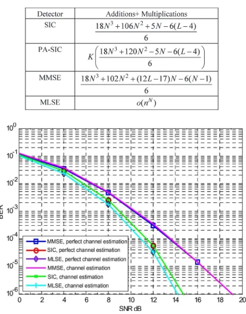
TABLE I
COMPUTATIONALCOMPLEXITY OFVARIOUSSCHEMES FORONECODING FRAMEWITHLENGTHN;LIS THENUMBER OFTAPS;
[image:6.594.305.549.103.414.2]BPSK CONSTELLATIONS
Fig. 1. SIC. Frequency-selective time-invariant fading channels; length of the frame= 64, taps= 3; BPSK. (a) Perfect channel estimation. (b) Channel estimation.
C. Computational Complexity Analysis
In this section, we show the complexity of the SIC, PA-SIC, MMSE, and MLSE detectors in terms of the number of addition and multiplication operations. The resulting values are given in Table I, which are obtained by inspection of the relevant algorithms.
From the table, we observe that although the SIC slightly outper-forms the MMSE, they are of the same complexity ordero(n3). For the PA-SIC scheme, its complexity is proportional to the number of SIC branches, which can be obtained by the sum of the addition and multiplication operations of all the SIC detectors. The MLSE has the highest degree of complexity. Details of the computational complexity of matrix inversion can be found in [19]. As we can see from the table, the complexity of the SIC is very close to that of the minimum mean square error (MMSE), whereas that of the PA-SIC is aboutKtimes the complexity of the SIC, whereKis the number of branches.
IV. SIMULATIONRESULTS
In all simulations, for simplicity, we consider only a system with two transmit antennas and one receive antenna, and BPSK and 16-quadrature amplitude modulation (16-QAM) constellations are used to generate a rate of 1- and 4-b/s/Hz transmission, respectively. Carrier frequency fc= 2 GHz, symbol period Ts= 128/(3.84×
646 IEEE TRANSACTIONS ON VEHICULAR TECHNOLOGY, VOL. 57, NO. 1, JANUARY 2008
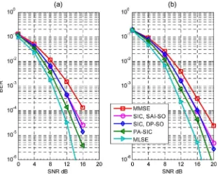
Fig. 2. SIC. Doubly selective fading channels; length of the frame= 64, taps= 3,k= 3,FdTs= 0.0093; BPSK. (a) Perfect channel estimation. (b) Channel estimation.
tofdTs= 0and 0.0093, respectively, wherefd=vfc/c, andcis the
speed of light).
In Fig. 1, simulation results for the SIC detector are illustrated in comparison with those of the conventional MMSE and the optimal MLSE decoder. Performance is determined over frequency-selective time-invariant fading channels. As shown in (12) and (13), the decod-ing ofs1 ands2 can be separated, and thus, the SIC algorithm can be applied to recovers1 ands2, respectively. From the figure, it can be observed that at BER= 10−4, the performance is 4 dB better than that of the MMSE equalizer, and there is only 0.5-dB loss as compared to that of the MLSE decoder. We can achieve that performance in a relatively slow fading environment, where the SIC detector is able to provide near-optimal performance with much lower computational complexity. Since channel estimation is accurate enough, we can observe from Fig. 1 that there is almost no difference between the curves that are obtained with the channel estimation and those with perfect channel knowledge at the receiver.
Fig. 2 shows the simulation results in doubly selective fading channels. From the simulation results with perfect channel estimation in Fig. 2(a), we can see that the SIC with SAI-SO can obtain about 2-dB gain over the MMSE at BER= 10−4. The power ordering is useful. At a high SNR, the performance with this ordering is better than the detector using the SAI-SO. For the PA-SIC detector, here, we only choose three branches with three different SOs—SAI-SO, DP-SO, and one random SO. It can be observed that the PA-SIC provides a gain of about 2 dB over that of the SIC receiver. The MLSE decoder gives the best performance; however, at BER= 10−4, there is only 1-dB loss using the PA-SIC withK= 3. Note that the complexity of the MLSE is very high. We also include the results that are obtained by channel estimation, as shown in Fig. 2(b), and thus, some estimation errors are introduced. We can observe that the performance of all detectors degrades due to the channel estimation errors: around 2-dB loss can be observed in comparison with the corresponding curves in Fig. 2(a). However, the conclusion is the same as the case with perfect channel estimation.
Fig. 3 shows the simulation results for the PA-SIC with perfect channel estimation in the doubly selective fading environment. Here,
Fig. 3. PA-SIC. Doubly selective fading channels; length of the frame= 4, taps= 2,FdTs= 0.0093,k= 1, 5, 7, 10, and 24; BPSK.
we focus on the optimal PA-SIC that tests all decoding possibilities and presents an exhaustive search problem. For simplicity, we set the frame length equal to four and the number of taps to two. Note that because of the exponential complexity of the exhaustive search, we had to focus on a very small frame length. Several different SIC SOs are used in parallel.
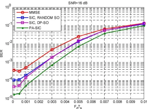
Fig. 4. SIC and PA-SIC. Doubly selective fading channels; length of the frame= 4, taps= 2,k= 24, with channel estimation; BPSK; SNR= 16dB.
Fig. 5. SIC. Doubly selective fading channels; length of the frame= 64, taps= 3,k= 3,FdTs= 0.0093, 16-QAM. Channel estimation.
In Fig. 4, simulation results are plotted over doubly selective fading channels against Doppler shift at SNR= 16 dB, and LS channel estimation is performed using training sequences at the receiver end. The results show that the SIC and the PA-SIC (all possibilities:4! = 24) can provide relatively better performance than the MMSE forFdTs
less than 0.01. We also note from the comparison of Fig. 4 that at low FdTs(up to 0.005), a higher SNR can lead to much better performance.
However, asFdTs increases, there will be more channel estimation
errors introduced so that the performance gains obtained in Fig. 4 are no longer clear.
Last, to show that our SIC and PA-SIC are not limited to BPSK constellations, in Fig. 5, we apply 16-QAM to generate a 4-b/s/Hz transmission rate. The simulations are obtained under doubly selec-tive fading channels withFdTs= 0.0093, and channel estimation is
employed. From the results, we can come to the same conclusion that the SIC can give better performance than the MMSE, and SO is useful to obtain better performance. The PA-SIC provides much better performance than the SIC due to the soft combining of the output from each SIC branch.
V. CONCLUSION
In this paper, we propose two schemes for the TR-STBCs to combat frequency-selective fading. In relatively time-invariant environments,
the SIC can be used to recover the original data with promising performance and very low complexity. For doubly selective fading channels, we further parallel-concatenate a certain number of SIC detectors with different signal decoding sequences and combine the soft output of each individual SIC. Simulation shows that the PA-SIC is very robust and can provide much better performance than the SIC and the MMSE, and the tradeoff between computational complexity and system performance can be easily realized by adjusting the number of SIC subbranches.
APPENDIX
In this section, we aim to simplify the matrix inversion term. For (18), rewriting the multiplication term inexp(·), we can obtain
(˜y−jksk)HΛ
−1
k (˜y−jksk)
= ˜yHΛ−1
k y˜+|sk|2jHkΛ
−1
k jk−2Re
˜ yHΛ−1
k jksk
.
The first term is a constant, and thus, we do not need to consider it in probability computation, such that we can concentrate on the term that needs matrix inversion, i.e.,
Λ−1
k =
JHk+1,2NJk+1,2N|s|2+σ2HHI
−1
= 1
σ2HH −
JH
k+1,2NJk+1,2N|s|2
σ2|s|2JH
k+1,2NJk+1,2NHH+σ4H2H
whereJH
k+1,2NJk+1,2Ncan be initially obtained by calculatingHHH
and storing it in the memory. As a result, the matrix inversion is no longer required, and the term inexp(·)of (18) can be represented as
(˜y−Jksk)HΛ
−1
k (˜y−Jksk)∝ |sk|2jHkΛ
−1
k jk−2Re
˜ yHΛ−1
k jksk
.
REFERENCES
[1] G. J. Foschini and M. J. Gans, “On limits of wireless communications in a fading environment when using multiple antennas,” Wirel. Pers. Commun., vol. 6, no. 3, pp. 311–335, Mar. 1998.
[2] I. E. Telatar,Capacity of Multi-Antenna Gaussian Channels, Jun. 1995. AT&T Bell Labs Intern. Rep.
[3] I. E. Telatar, “Capacity of multi-antenna Gaussian channels,”Eur. Trans. Telecommun., vol. 10, no. 6, pp. 585–595, Nov./Dec. 1999.
[4] G. J. Foschini, “Layered space-time architecture for wireless communi-cation in a fading environment when using multi-element antennas,”Bell Labs Tech. J., vol. 1, no. 2, pp. 41–59, Autumn 1996.
[5] S. M. Alamouti, “A simple transmit diversity technique for wireless com-munications,”IEEE J. Sel. Areas Commun., vol. 16, no. 8, pp. 1451–1458, Oct. 1998.
[6] V. Tarokh, H. Jafarkhani, and A. R. Calderbank, “Space-time block coding for wireless communications: Performance results,”IEEE J. Sel. Areas Commun., vol. 17, no. 3, pp. 451–460, Mar. 1999.
[7] V. Tarokh, H. Jafarkhani, and A. R. Calderbank, “Space-time block codes from orthogonal designs,”IEEE Trans. Inf. Theory, vol. 45, no. 5, pp. 1456–1467, Jul. 1999.
[8] E. Lindskog and A. Paulraj, “A transmit diversity scheme for channels with interference,” in Proc. IEEE ICC, New Orleans, LA, Jun. 2000, vol. 1, pp. 307–311.
[9] Z. Liu, G. Giannakis, A. Scaglione, and S. Barbarossa, “Decoding and equalization of unknown multipath channels based on block precoding and transmit-antenna diversity,” in Proc. 33rd Asilomar Conf. Signals, Syst., Comput., Oct. 1999, vol. 2, pp. 1557–1561.
[10] H. Bolcskei and A. J. Paulraj, “Space-frequency coded broadband OFDM systems,” inProc. IEEE WCNC, Chicago, IL, Sep. 2000, pp. 1–6. [11] N. Al-Dhahir, “Single-carrier frequency-domain equalization for
space-time block-coded transmissions over frequency-selective fading channels,”IEEE Commun. Lett., vol. 5, no. 7, pp. 304–306, Jul. 2000. [12] S. Zhou and G. Giannakis, “Single-carrier space-time block-coded
648 IEEE TRANSACTIONS ON VEHICULAR TECHNOLOGY, VOL. 57, NO. 1, JANUARY 2008
[13] N. Al-Dhahir, “Overview and comparison of equation schemes for space-time coded signals with application to EDGE,” IEEE Trans. Signal Process., vol. 50, no. 10, pp. 2477–2488, Oct. 2002.
[14] S. Geirhofer, L. Tong, and A. Scaglione, “Time-reversal space-time cod-ing for doubly-selective channels,” inProc. IEEE WCNC, Las Vegas, NV, 2006, pp. 1638–1643.
[15] J. Luo, K. R. Pattipati, P. K. Willett, and F. Hasegawa, “Near-optimal multiuser detection in synchronous CDMA using probabilistic data as-sociation,”IEEE Commun. Lett., vol. 5, no. 9, pp. 361–363, Sep. 2001. [16] Y. Jia, C. Andrieu, R. J. Piechocki, and M. Sandell, “Gaussian
approximation based mixture reduction for near optimum detection in MIMO systems,”IEEE Commun. Lett., vol. 9, no. 11, pp. 997–999, Nov. 2005.
[17] P. W. Wolniansky, G. J. Foschini, G. D. Golden, and R. A. Valenzuela, “V-BLAST: An architecture for realising very high data rates over the rich-scattering wireless channel,” in Proc. ISSSE, Pisa, Italy, Sep. 1998.
[18] G. Barriac and U. Madhow, “PASIC: A new paradigm for low-complexity multiuser detection,” inProc. Conf. Inf. Sci. Syst., Mar. 21–23, 2001. [19] G. H. Golub and C. D. Loan,Matrix Computations. Baltimore, MD:
Johns Hopkins Univ. Press, 1996.
Frequency Domain Equalization and Interference Cancellation for TD-SCDMA Downlink in Fast
Time-Varying Environments
Yuhong Wang, Ying-Chang Liang, and Wing Seng Leon
Abstract—In time division synchronous code division multiple access downlink, one computationally efficient receiver for fast time-varying en-vironments is the subblock processing receiver, which utilizes overlap-save fast Fourier transform. In this paper, we first analyze the interferences involved with the subblock processing method proposed by Held and Kerroum and then propose a new subblock processing receiver for fast time-varying channels. The proposed receiver consists of two stages. In the first stage, the entire received chip block is partitioned into overlapping subblocks and they are individually equalized and despread. We then artificially generate the interferences caused by adjacent blocks and the unwanted chip interference within the same subblock and eliminate them from the received data signals. Then, a second subblock processing is per-formed to detect the transmitted symbols. A practical channel estimator is also introduced to be used with the proposed receiver. Simulation results have shown that the proposed receiver provides a significant performance improvement as compared with the conventional subblock processing method.
Index Terms—Frequency domain equalization (FDE), interference can-cellation, iterative algorithms, time division synchronous code division multiple access (TD-SCDMA).
I. INTRODUCTION
The third generation cellular communication systems are based on code division multiple access (CDMA) technology due to its capability to support flexible and high rate services. Although the RAKE receiver performs maximal-ratio combining by capturing the energies from the various multipath components of the channel, it is not able to restore the orthogonality of the spreading codes, which is destroyed
Manuscript received January 13, 2005; revised October 6, 2005, July 14, 2006, January 9, 2007, and May 1, 2007. The review of this paper was coor-dinated by Dr. Y.-P. E. Wang.
Y. Wang is with ST Electronics (Satcom & Sensor Systems) Pte Ltd., Singapore 609602 (e-mail: [email protected]).
Y.-C. Liang and W. S. Leon are with the Institute for Infocomm Research, Singapore 119613 (e-mail: [email protected]; [email protected]. edu.sg).
Digital Object Identifier 10.1109/TVT.2007.905259
after transmission over time dispersive multipath channels. Thus, the multiple access interference (MAI) and interfinger interference (IFI) ultimately lead to an irreducible bit error rate (BER) floor if the RAKE receiver is used. Therefore, chip-level block-based equalization receiv-ers for CDMA systems have been proposed to restore the orthogonality of the spreading codes and thereby alleviating the MAI and IFI [1]–[7]. In this paper, we consider the time division synchronous code divi-sion multiple access (TD-SCDMA) system, which has been adopted by the Third Generation Partnership Project as the low chip rate version of the Universal Mobile Telecommunications System time division duplex. For TD-SCDMA, each frame interval is 10 ms and it contains two subframes. Each subframe consists of seven slots [11], [12]. Each slot contains two data bearing blocks, each with 352 chips. The midamble between the two data bearing blocks, containing 144 chips, is designed for the purpose of channel estimation. One di-rect method is to estimate the channel coefficients using the midamble and then equalizing the two data blocks. This approach assumes that the channel is essentially static over the entire slot. For time-varying environments, an alternative solution is to employ subblock processing as proposed in [1], which estimates the channel estimates for each subblock, and the channel can be considered stationary, and thus, block equalization can be applied. However, subblock processing proposed in [1] introduces interference between the subblocks and interference due to the edge effect within each subblock because of the subblock dividing, which leads to an irreducible BER floor.
In this paper, we propose a novel subblock processing receiver for TD-SCDMA downlink in fast fading environment. The new receiver consists of two stages. The first stage is similar to the conventional subblock processing equalizer [1]. Using the decisions derived from the first stage, the receiver then artificially generates the estimates of the interferences, which are then eliminated from the received data chip block. A second subblock processing is finally performed to detect the transmitted symbols. We also present a practical channel estimation method to be used with the proposed receiver.
This paper is organized as follows. In Section II, the downlink transmission model of TD-SCDMA is described, and the conventional subblock processing method is introduced. In Section III, the proposed receiver and channel estimator are presented. In this section, the complexity of the proposed receiver is also compared with that of the conventional receiver. Computer simulation results are given in Section IV for various channel environments. Finally, we conclude this paper in Section V.
II. SYSTEMMODEL ANDCONVENTIONAL SUBBLOCKPROCESSINGRECEIVER
In this section, we will briefly describe the TD-SCDMA downlink system and introduce the conventional subblock processing receiver.
A. Channel Model
We consider a single cell TD-SCDMA downlink with processing gainQandKactive users. The data symbols designed for allKactive users are synchronously and simultaneously transmitted from the base station to the mobile units over the same downlink channel. Within each time slot, there are two data bearing blocks. For each block, N data symbols are transmitted for each of the K users. The data symbols may be written as
d(k) =d(1k), d(2k), . . . , d(Nk)
T
(1)