ST U D IE S OF H E L IC O N WAVES
A N D P L A SM A C U R R E N T D R IV E
IN T H E SH EILA HELIAC
by
Beichao Zhang
January 1995
A thesis submitted for the degree of
Doctor of Philosophy
To my family —
especially my father and mother,
The theoretical model of the antenna-wave coupling described in section 3.2.5 was developed by Dr. G.G. Borg. The theoretical description of the currents driven by ponderomotive forces described in section 5.2 follows reference [35] in Chapter 5 and the theoretical results were obtained by the use of the WITAC code, which was developed by Dr. V. Petrzilka.
The results presented in this thesis are my original research except for where otherwise acknowledged.
Beichao Zhang
A b s tr a c t
This thesis describes in detail the helicon wave excitation by an electrostatically shielded half-turn loop antenna, and the plasma formation by two different an tennas, an unshielded partial-turn loop antenna and double-saddle loop antenna in the SHEILA heliac. Plasma current driven by helicon waves and other non- inductive mechanisms is also studied.
A comparison between theoretical calculations and experimental measurements of helicon wave coupling by the shielded half-turn loop antenna is presented. Despite the complicated heliac geometry, the wave dispersion, field profiles and antenna radiation resistance can be well described by a cylindrical uniform plasma theory. In the investigation of the antenna radiation resistance, a simple formula relating the radiation resistance to the measured wave magnetic field per unit antenna current is derived and given. The scaling of these results to the Heliac-1 (H-l) a larger heliac, is discussed.
The unshielded partial-turn loop antenna and the double-saddle loop antenna are used for plasma formation by helicon waves. The density produced by the two antennas is compared with that produced by the double loop antenna alone. The wavefields and antenna radiation resistances of the two antennas are mea sured separately. It is found that the double loop antenna has a higher radiation resistance and much higher plasma generation efficiency. Even though the un shielded partial-turn loop antenna could only produce a very low density plasma at high power, it produces comparable wavefields to those of the double-saddle loop antenna in a high density plasma. This may suggest that the measured travelling wave fields play little role in the plasma formation and that the high density produced by the double-saddle loop antenna may be due to the effect of its strong near fields. The particle confinement time is also estimated from beating technique using two slightly different frequencies on the two antennas.
the current in the low density regime is caused by pressure-driven transport. The
m easured asym m etric radial profile of the current at low density may indicate a
m ixture of the uni-directional bootstrap current with the bi-directional Pfirsch-
Schliiter current. These m easurem ents are com pared with theory and a reasonable
A u t h o r ’s P u b lic a t io n s
'Helicon Wave Excitation and Propagation in A Toroidal Heliac: Experiment and Theory
B.C. Zhang, G.G. Borg, and B.D. Blackwell,
In press, Physics of Plasmas, 2 (3), March (1995).
‘Currents Driven by Ponderomotive Forces in the SHEILA Heliac Plasma \
B.C. Zhang. V. Petrzilka, B.D. Blackwell, and G.G. Borg, Submitted to Journal of Plasma.
4Experimental Results of RF produced Plasmas in the H-l Toroidal Heliac
B.D. Blackwell, G.G. Borg, S.M. Hamberger, J. Howard, D.L. Rudakov, L.E. Sharp, M.G. Shats, G.B. Warr, and B.C. Zhang.
In press, 6th Int. Toki Conf. on Plasma Phys. and Contr. Nul. Fusion, Toki, Japan, Nov. 1994.
‘H-l Radio Frequency System and Initial Studies of Plasma Formation\
G.G. Borg, B.D. Blackwell, D.L. Rudakov, D. Schneider, M.G. Shats, L.E. Sharp, B.C. Zhang.
In press, Fusion Engineering and Design, January (1995).
‘First Experimental Results and Recent MHD Studies for the H-l Heliac’,
B.D. Blackwell, G.G. Borg, R.L. Dewar, H.J. Gardner, S. M. Hamberger, J. Howard, D. Rudakov, L.E. Sharp, M. Shats, R. Tumlos, G. Warr, B.C. Zhang. W.A. Cooper, P.R. Garabedian, and T. Hayashi,
Seville, Spain, 1994), IAEA-CN-60-60/A6/C-P-4.
‘A simple magnetic probe with inherent electrostatic rejection , P.K. Loewenhardt, B.D. Blackwell, Beichao Zhang.
Review of Scientific Instruments. 64 (11), 3334 (1993).
’Measurements of Neoclassical Currents in A Toroidal Heliac Plasma \
B.C. Zhang, B.D. Blackwell, G.G. Borg,
In preparation.
‘An Comparison of Helicon Wave Excitation by Two Different Antennas’,
B.C. Zhang. B.D. Blackwell, G.G. Borg,
In preparation.
‘Experimental Fast Wave Studies in A Toroidal Heliac Plasma
B.C. Zhang, B.D. Blackwell, G.G. Borg, S.M. Hamberger,
The 35th Meeting of the American Physical Society-Division of Plasma Physics, St Louis, Missouri, U.S.A, Nov. 1993.
‘First Operation of H -l\
S.M. Hamberger, B.D. Blackwell, G.G. Borg, J. Howard, D. Rudakov, L. E. Sharp, M. Shats, G. Warr, B.C. Zhang.
9th IAEA International Workshop on Stellarator, Garching, Germany, May, 1993.
"First Results from the H-l Heliac ’,
the AINSE-White Plasma Physics Conference, Canberra, July. 1993.
‘Plasma Formation and RF Current Drive in SHEILA \
B.C. Zhang. B.D. Blackwell, G.G. Borg, S.M. Hamberger, Plasma Formation and RF Current Drive in SHEILA,
The AINSE-White Plasma Physics Conference, Canberra, July. 1993.
‘Studies of Plasma Formation and Nonlinear waves in BASIL \
D. Schneider, B.D. Blackwell, G.G. Borg, R.W. Boswell, B.C. Zhang,
the AINSE-White Plasma Physics Conference, Canberra, July. 1993.
1First Operation of H -l\
S.M. Hamberger, B.D. Blackwell, G.G. Borg, H.J. Gardner, J. Howard, S.L. Painter, L.E. Sharp, M. Shats, R. Tumlos, B.C. Zhang.
Bulletin of the American Physical Society, America, 37 (6), Nov, 1992.
‘An 8 Channel 0.4 - 40 MHz Phase and Amplitude Detector for Plasma Wave Studies
R. Dehner, G. Borg, B. Zhang,
A c k n o w le d g e m e n ts
I am grateful to the staff and my fellow students of the Plasma Research Labo ratory in the Research School of Physical Sciences and Engineering for their help during my studies.
I am particularly grateful to my supervisors, Dr. Boyd D. Blackwell and Prof. S.M. Hamberger. It is Dr. B.D. Blackwell who has guided me into the exciting and enjoyable field of radio frequency plasma waves. His experimental talents, broad experience and great insight into physical problems have benefited me to put this work into a proper form. I have gained greatly from the discussions with him during my four years’ study here. Prof. Hamberger provided me with the opportunity to do a Ph. D degree and his efforts allowed me to take up the Australian National University scholarship after three and half years1 delay during which I was in difficulties. He has also given me many helpful suggestions for this work. Besides these, he is always a very encouraging, supportive and helpful source in my other aspects.
Dr. G.G. Borg is always willing to discuss my questions regarding to all aspects of the experimental results and interpretation. I am very grateful to his stimu lation for a better understanding of physics of the antenna-wave coupling, many long discussions and his allowing me the use of his antenna-wave coupling code. He also helped me with technical aspects of rf signal detection and associated electronics. I wish to thank Dr. Petrzilka of the Institute of Plasma Physics of the Czech Republic for his very helpful discussion and collaboration toward an understanding of the currents driven by helicon wave ponderomotive forces and for the use of his WITAC code.
computer. Discussions with Prof. Thomas H. Stix of the Princeton Plasma Physics Laboratory, Prof. Noah Hershkowitz of the University of Wisconsin, and Prof. Paul M. Bellan of the California Institute of Technology are gratefully acknowledged.
I would like to thank my fellow students who have helped me with various aspects; without them, this work could be much delayed. Dr. Peter K. Loewenhardt helped me get familiar with the experimental apparatus and his double-saddle loop antenna has enabled me to obtain a high plasma density in SHEILA. Dr. Chunshi Cui helped me get familiar with the research environment and western culture. Mr. Bert Ellingboe, Mr. Darryn Schneider and Mr. George Warr spent time for proof reading parts of this thesis or helping my English. I also would like to thank Ms. Xujuan Dai and Mr. Roy Tumlos for their kindness and hospitality.
I wish to thank the technical staff of the Plasma Research Laboratory and other staff in the Research School. In particular I would like to thank Mr. Ray Kimlin for his consistent effort in maintaining and problem-solving of the electrical sys tem of SHEILA, and Mr. John Wach and Mr. Eddie Wedhorn for maintaining the SHEILA vacuum system. I would like to thank Mr. Bill Alford and Ms. Julie Dalco for patiently helping me with many computer problems. I also would like to thank the staff in the Electronic Unit who provided many conveniences for me by lending me instruments and obtaining electronic components.
The kindness and help and support I received for the last four years from my Chinese friends in Australia have made this all possible. In particular I would like to thank my friends in the University for having so many exciting activities together which made my last four years’ life more enjoyable.
C o n te n ts
1 In tr o d u c tio n
Bibliography...
2 E x p e r im e n ta l A p p a ra tu s and P la sm a D ia g n o stic s
2.1 Introduction...
2.2 S H E IL A ... 2.2.1 The Magnetic Field S y s t e m ...
2.2.2 Ancillary E q u ip m e n t... 2.3 Radio Frequency Systems for Plasma Formation and Wave Coupling
2.3.1 Introduction...
2.3.2 RF A n te n n a s ...
2.3.3 Radio Frequency E quipm ent...
2.4 Diagnostics ...
2.4.1 Introduction...
2.4.2 Magnetic Probes and Signal Processing...
2.4.3 Magnetic Probe Signal Analysis S y s te m ...
2.4.4 Measurements of Antenna L o a d in g ...
2.4.5 RF Power Splitter ...
2.4.6 Rogowski C o il...
2.4.7 Langmuir P r o b e s ... 42
2.5 Bibliography... 45
3 H e lic o n W a v e E x c it a t io n a n d P r o p a g a t io n 48 3.1 Introduction... 48
3.2 Theoretical R e s u lts ... 49
3.2.1 Introduction... 49
3.2.2 Helicon Wave Propagation in S H E IL A ... 49
3.2.3 Effect of Ion Motion on the Dispersion R e la tio n ... 58
3.2.4 Effect of Electron Inertia on the Dispersion Relation . . . 61
3.2.5 Antenna Loading M o d e l... 63
3.2.6 Collisional D a m p in g ... 67
3.2.7 Coordinate System s... 69
3.3 Experimental R e su lts... 69
3.3.1 Wave Field M easurem ents... 70
3.3.2 Identification of Poloidal Mode S tru c tu re ... 72
3.3.3 Radial Structure of the Wave F ield s... 74
3.3.4 Wavelength M easurem ents... 76
3.3.5 Verification of Wave D isp e rsio n ... 79
3.3.6 Variation in Antenna L o a d in g ... 80
3.4 Summary and E x te n sio n ... 84
3.4.1 Summary of Results ... 84
3.4.2 Scaling to H - l ... 84
4 H e lic o n W ave P la sm a F orm ation by T w o D ifferen t A n ten n a s 91
4.1 Introduction... 91
4.2 Plasma Formation E x p erim en ts... 92
4.2.1 Dependence of Density on RF Power and Antenna Phasing 92 4.2.2 Dependence of Plasma Density on Filling Pressure... 94
4.2.3 Dependence of Density on Magnetic Field ... 98
4.2.4 Density Profile M easurem ents... 99
4.3 Antenna Radiation Resistance Measurements... 101
4.3.1 Introduction... 101
4.3.2 Radiation Resistance for the Double-Saddle Loop Antenna 102 4.3.3 Radiation Resistance for the Unshielded Partial-Turn Loop A n te n n a ...105
4.4 Wave Field C om parisons... 107
4.5 Estimation of Particle Confinement T im e ...I l l 4.6 Conclusion... 113
4.7 Bibliography...-Q4 5 D r iv en C urren ts: E x p e r im e n t and T h e o r y 116 5.1 Introduction... 116
5.2 Theory of Non-resonant Current Drive by Helicon W a v e s ... 118
5.3 Theoretical Results for Neoclassical C u rren ts...121
5.4 Current Measurement and D iscussion...129
5.4.1 Dependence of Current on Density ...129
5.4.2 Helicon Wave Driven Current at High D e n s ity ... 131
C h a p te r 1
I n tr o d u c tio n
The study of plasm a physics in the pursuit of controlled therm onuclear fusion,
which has become its prim ary purpose, is directed into two m ain areas, heating
and confinement. For these purposes, a variety of hot plasm a confinement devices
has been developed and investigated, such as the tokam ak, the stellarator, the
m irror and the spherom ak, the ö-pinch, etc.. In these devices, a strong m agnetic
field is needed to confine the plasm a particles. Toroidal machines have recently
dom inated fusion plasm a research by virtue of their b etter plasm a confinement,
particularly in tokam aks into which the greatest effort has been put and in which
the highest plasm a param eters have been obtained.
The confinement m agnetic field geom etry in a tokam ak is produced by a toroidal
field generated by external coils and a poloidal field which is provided by a cir
culating, inductively produced plasm a current. The plasm a current serves the
additional purpose of ohm ically heating the plasm a. This current may however
also produce a disruptive instability which suddenly term inates the plasm a. Since
the plasm a current profile is not easily controlled in a tokam ak, the m agnetic con
figuration is essentially unknown, so th a t the role of m agnetic configuration on
stability and tran sp o rt can not be studied system atically.
The fundam ental advantages of stellarators have caused the stellarator to regain
concept was initiated by Spitzer [2] in 1951 and up to 1968 this type of device
was considered as the m ain candidate for therm onuclear fusion reactors. Since
the developm ent of the first 3-D m agnetohydrom agnetic (MHD) equilibrium and
stability codes in 1980s, the stellarator is regarded as a suitable high tem p era
tu re plasm a confinement geom etry again. In general, the stellarator is a plasm a
current-free device and does not suffer from the plasm a current disruption of a
tokam ak. The confinement m agnetic field in a stellarator is established entirely
by external field coils. The m agnetic configuration and the plasm a profiles can
be controlled by adjusting currents in external m agnetic field coils and, in the
absence of finite-pressure plasm a, can be predicted quite accurately. The stellara
tor can be designed to operate continuously. These features make it much easier
to investigate plasm a tran sp o rt, MHD equilibrium and stability in this type of
device. High b eta operation may be another advantage of stellarators, and is
im p o rtan t for effective operation of a commercial fusion reactor.
One of the m ost im p o rtan t topics for stellarators is to investigate the effect on
the plasm a confinement properties of various quantities used to characterize the
configuration. There are four m ain types of stellarator configurations [3, 4, 5, 6]
currently under active investigation [1]. These configurations differ from each
other by em phasizing different field characteristics, such as the rotational tra n s
form per field period, the shear of th e m agnetic field lines and th e sign and depth
of any m agnetic well etc.. The helical axis stellarator, or heliac, is one of these
types of stellarator.
In heliac devices, such as SHEILA [2], H-l [8], and T J-II [9] (under construction
in Spain), th e m agnetic configurations feature a helical axis, a large rotational
transform per field period, a low shear and generally a substantial global mean
m agnetic well. The m agnetic geometry, especially the ‘flexible1 heliac [10], has
a high degree of tu n ab ility with the vacuum m agnetic well, rotational transform
and m agnetic shear controlled alm ost independently by adjusting the currents in
th e external coils. These distinguishing features and advantages provide heliacs
on plasma transport.
SHEILA was the first toroidal heliac plasma device in the world. Since the first operation of SHEILA in 1984. many interesting experiments have been conducted on it, including the electron beam mapping of the magnetic flux surfaces [6, 7], the studies of the effect of the heliac plasma configurations [3, 4, 5] on confinement, and on the drift waves [16], studies of the property of the plasma formation by microwaves [17] and helicon waves [47, 19], the helicon wave induced plasma transport [20, 21, 23] and current drive [24, 25] (described in Chapter 5), the antenna-wave coupling behaviour in the SHEILA plasma (described in Chapter 3 and 4), observation of the neoclassical current (described in Chapter 5). All these studies have provided a better understanding of heliac plasma physics, the heliac magnetic configuration and plasma wave physics.
Loewenhardt, et al. introduced helicon waves into the SHEILA plasma by using a double-saddle loop antenna [47]. This technique produced a plasma density up to 5 x l0 19 m -3 in SHEILA [47, 48]. This density is approximately ten times higher than the previous highest density produced by ohmic heating with low radio frequency (94 kHz) power (400 watts) [5]. The structure of the wave fields and some of their propagation properties were investigated. The phase velocity derived from parallel wavelength indicated that there was Landau damping of the excited helicon waves in some cases.
The work presented in this thesis discusses helicon wave excitation by an electro statically shielded half-turn loop antenna; comparison of plasma formation and wave fields by two different antennas, the double-saddle loop antenna and an un shielded partial-turn loop antenna; helicon wave current drive and measurements of the neoclassical current in SHEILA.
Electrostatically shielded partial-turn loop antennas are widely used for Ion Cy clotron Resonance Heating (ICRH) for thermonuclear plasma research [46, 47, 48]. There is a large database available from ICRH experiments, particularly from tokamaks. Some stellarators have also employed this frequency range for plasma formation and heating purposes [49, 50, 51, 52, 53]. The H-l device has been designed to heat its plasma using this technique and to investigate the physics of wave coupling into a heliac plasma. In preparation for this, this type of antenna has been studied in the small SHEILA heliac to explore some of the basic physics of the interaction of waves with a heliac plasma. Investigation of the propagation behaviour of the waves and the antenna-wave coupling properties have been made for this antenna in SHEILA. The application of these results to H-l is expected.
SHEILA. Since plasm a current introduces an ex tra m agnetic field components
which can deteriorate the original m agnetic field configuration in otherwise care
fully designed stellarators, it is necessary to understand the mechanisms which
cause any currents arising in this system. This may allow stellarator physicists
to improve the design of a stellarator or to find a way to restrict or com pensate
the currents.
This thesis presents the recent studies in SHEILA. C hapter 2 gives a brief de
scription of the SHEILA heliac system and describes the diagnostic techniques,
which have been involved in these experim ents. C hapter 3 describes the inves
tigation of helicon waves excited by the electrostatically shielded half-turn loop
antenna. The antenna-w ave coupling properties are studied and a simple cylin
drical model is developed. The eigenmodes of the wave fields are identified and
the wave dispersion relation and th e radiation resistance are m easured in the
range of frequencies 4 - 2 4 MHz, and com pared with theory. An extension of
this work to H -l is discussed in its last section. C hapter 4 presents the results
of plasm a production experim ents conducted by the combined use of the double
saddle loop an ten n a and the unshielded p artial-tu rn loop antenna. The plasm a
density generated by the double-loop antenna is m easured and the density per
turbations introduced by th e unshielded p artial-tu rn loop antenna is observed.
The wave fields and the radiation resistances of the two antennas are measured
and com pared. C hapter 5 studies the DC plasm a currents observed in SHEILA
B ib lio g ra p h y
[1] B. A. Carreras, G. Grieger, J. H. Harris, J. L. Johnson, J. F. Lyon, 0. Motojima, F. Rau, H. Renner, J. A. Rome, K. Uo, M. Wakatani, H. Wobig, Nucl. Fusion, 28, 1613 (1988).
[2] L. Spitzer, Phys. Fluids 1, 253 (1958).
[3] A. H. Boozer, T. K. Chu, R. L. Dewar, et al., in Plasma Physics and Con trolled Nuclear Fusion Research (Proc. 9th Int. Conf. Baltimore, 1982), 3,
IAEA, Vienna 129 (1983).
[4] U. Brossman, W. Dommanschk, F. Herrnegger, et al., in Plasma Physics and Controlled Nuclear Fusion Research (Proc. 9th Int. Conf. Baltimore, 1982),
3, IAEA, Vienna 141 (1983).
[5] J. F. Lyon, B. A. Carreras, J. H. Harris, U. Brossman, W. Dommanschk, F. Herrnegger, et al., in Plasma Physics and Controlled Nuclear Fusion Re search (Proc. 9th Int. Conf. Baltimore, 1982), 3, IAEA, Vienna 115 (1983).
[6] K. Uo, Nuclear Fusion 25, 1243 (1985).
[7] B. D. Blackwell, S. M. Hamberger, L. E. Sharp and X. H. Shi, Nuclear Fusion, 25, 1485 (1985).
[8] S. M. Hamberger, B. D. Blackwell, L. E. Sharp, and D. B. Shenton, Fusion Technology, 17, 123 (1990).
[10] J. H. Harris, J. L. Cantrell, T. C. Hender, B. A. Carreras, B. N. Morris, Nuclear Fusion. 25 623 (1985).
[11] T. Y. Tou, B. D. Blackwell, and L. E. Sharp, Rev. Sei. Instrum. 62, 1149 (1991) .
[12] B. D. Blackwell, J. Howard, and R. B. Tumlos, Rev. Sei. Instrum. 6 3, 4725 (1992) .
[13] B. D. Blackwell, S. M. Hamberger, L. E. Sharp, and X. H. Shi, Aust. J. Phys., 4 2, 73 (1989).
[14] X. H. Shi, S. M. Hamberger, B. D. Blackwell, Nuclear Fusion 28 (5), 859 (1988).
[15] Xuehua Shi, Ph.D. Thesis, Australian National University (1989).
[16] X. H. Shi, S. M. Hamberger, B. D. Blackwell, Nuclear Fusion 28 (5), 859 (1988).
[17] G. D. Conway and B. D. Blackwell, Plasma Physics and Controlled Fusion,
33 (2), 135 (1991).
[18] P. K. Loewenhardt, B. D. Blackwell, R. V. Boswell, G. D. Conway and S. M. Hamberger, Phys. Rev. Lett. 6 7, 2792 (1991).
[19] B. C. Zhang, G. G. Borg, B. D. Blackwell, Phys. of Plasmas, 2 (3), March (1995), in press.
[20] V. Petrzilka, Australian Journal of Physics 43 (3), 315 (1994).
[21] R. L. Dewar and V. Petrzilka, submitted in Australian J. of Phys.
[22] A. G. Elfimov, V. Petrzilka, J. A. Tataronis, Physics of Plasmas, 1 (9), 2882 (1994).
[23] V. Petrzilka and J. A. Tataronis, Plasma Physics and Controlled Fusion 36
[24] B. C. Zhang, B. D. Blackwell, V. Petrzilka, subm itted to Journal of Plasm a
Physics.
[25] P. Aigrain, Proc. Int. Conf. on Sem iconductor Physics, Prague (Lon-
don:B utterw orths), (1960) p. 224.
[26] R. Bowers, C. Legendy, and F. E. Rose, Phys. Rev. Lett., 7, 339 (1961).
[27] G. N. Harding and P. C. Thonem ann, Proc. Phys. Soc., 85, 317 (1965).
[28] A. Libchaber and R. Veilex, Phys. Rev., 127 774 (1962).
[29] J. A. Lehane and P. C. Thonem ann, Proc. Phys. Soc., 85, 301 (1965).
[30] J. P. Klozenberg, B. M cN am ara, P. C. T honem ann, J. Fluid Mech., 21, 545
(1965).
[31] F. F. Chen, Plasm a Phys. Controlled Fusion, 33, 339 (1991).
[32] H. A. Blevin and P. J. C hristiansen, Aust. J. Phys., 1966, 19, 501 (1966).
[33] B. Davies, J. Plasm a Phys. 4, 43 (1970).
[34] R. W. Boswell, J. Plasm a Phys, 31, 193 (1983).
[35] H. A. Blevin, P. J. C hristiansen and B. Davies, Physics Letters, 28A , 230
(1986).
[36] R. W. Boswell, J. Plasm a Phys., 31, 197 (1984).
[37] R. W. Boswell, Ph.D . thesis, Flinders U niversity of South A ustralia, (1970).
[38] R. W. Boswell, Phys. Lett. 3 3 A , 457 (1970).
[39] R. W. Boswell, Plasm a Phys. Controlled Fusion, 26, 1147 (1984).
[40] P. Zhu and R. W. Boswell, Phys. Rev. Lett. 63, 2805 (1989).
[41] A. Komori, T. Shoji, K. M iyam oto, J. Kawai, and Y. Kawai, Phys. Fluids
[42] Francis F. Chen, Laser and Particle Beams, 7, 551 (1989).
[43] P. Zhu, Ph. D Thesis, The Australian National University, 1990.
[44] P. K. Loewenhardt, Ph. D Thesis, The Australian National University, 1992.
[45] Francis F. Chen, in Proceedings of the Second International Conference on Plasma Physics, Kiev, U.S.S.R., edited by A. G. Sitenko (Naukova Dumka, Kiev, 1987), 4, 1378 (1987).
[46] V. P. Bhatnagar, J. Jacquinot, C. Gormezano, D. F. H. Start and the JET Team, Radio Frequency Power in Plasmas, the 9th Topical Conference on RF Power in Plasmas, Charleston, USA, 1991, edited by D. B. Batchelor, (American Institute of Physics, New York, 1992), p. 115.
[47] R. L. Pinsker, M. J. Mayberry, C. C. Petty, S. C. Chiu, M. Porkolab, R. Prater, Radio Frequency Power in Plasmas, the 9th Topical Conference on RF Power in Plasmas, Charleston, USA, 1991, edited by D. B. Batchelor, (American Institute of Physics, New York, 1992), p. 105.
[48] JFT-2 G ro u p , H e a tin g in T o ro id a l P la s m a s , th e 3 rd J o in t V a re n n a -G re n o b le
international Symposium, Grenoble, France, 1982, edited by C. Gormezano, G. G. Leotta, and E. Sindoni, (EURATOM-CEA Association, Italy, 1982), ECSC-EEC-EAEC(Euratom), EUR 7979 EN, 1, p. 259.
[49] D. J. Hoffman, J. L. Shohet, Nuclear Fusion, 2 3, 87 (1983).
[50] A. Hyoshi, M. Sato, A. Sasaki, T. Obiki, K. Uo, Nuclear Fusion, 14, 789
(1974).
[51] M. A. Rothman, R. M. Sinclair, I. G. Brown, J. C. Hosea, Phys. Fluids, 12 2211 (1969).
[53] M. D. Carter, A. I. Lysojvan, V. E. Moiseenko, N. I. Nazarov, O. M. Shvets, K. N. Stepanov, Nuclear Fusion, 30 (4), 723 (1990).
[54] N. J. Fisch, Rev. Mod. Phys. 4 1, 873 (1978).
[55] D. J. M. Wort, Plasma Phys. 13, 258 (1971).
[56] K. Ohkubo, et ah, Phys. Rev. Lett. 56, 2040 (1986).
[57] T. Ohkawa, Nuclear Fusion, 10, 185 (1970).
[58] W. H. M. Clark, et ah, Phys. Rev. Lett, 45, 1101 (1980).
[59] M. Murakami, B. A. Carreras, L. R. Baylor, G. L. Bell, T. S. Bigelow, A. C. England, J. C. Glowienka, H. C. Howe, T. C. Jernigan, D. K. Lee, V. E. Lynch, C. H. Ma, D. A. Rasmussen, J. S. Tolliver, M. R. Wade, J. B. Wilgen, and W. R. Wing, Phys. Rev. Lett., 66, 707 (1991).
[60] U. Gasparino, H. Maassberg, M. Tutter, WVII-A Team, Plasma Phys. Contr. Fusion, 30 (3), 283 (1988).
[61] S. Besshou et al., Plasma Phys. 2 6, 565 (1984).
[62] S. Yoshikawa and H. Yamato, Phys. Fluids, 9 (9), 1814 (1966).
[63] S. Morimoto, N. Yanagi, M. Nakasuga, T. Obiki, A. Iiyoshi, K. Uo, Nucl. Fusion, 2 8, (9), 1491 (1988).
C h a p te r 2
E x p e r im e n ta l A p p a r a tu s a n d
P la s m a D ia g n o s tic s
2.1
I n tr o d u c tio n
This chapter describes the experim ental apparatus used in the study of radio
frequency plasm a waves and the m easurem ent of plasm a currents in SHEILA.
The first section describes the SHEILA heliac device and its m agnetic configura
tion. T he second section gives a brief description of the wave excitation systems.
Finally, section 3 describes the plasm a diagnostics involved in the experim ent.
SHEILA is a prototype heliac stellarator, designed for the studies of fundam ental
plasm a behaviour of relevance to nuclear fusion. Some of the m ain operating
param eters of th e SHEILA heliac are listed in Table 2.1.
Table 2.1 T Y P IC A L SH EILA P A R A M E T E R S
M ain M agn etic Field: B 0 < 2.5 kG
M ajor P lasm a Radius: R = 18.75 cm
A verage M inor Radius: ä = 3.5 cm
P la sm a D ensity: n e < 3.2 x 1013 cm -3
E lectron T em perature: Te = 5.0 eV
The SHEILA plasma is generated by a double-saddle loop antenna described in section 2.3.2, with a low frequency power supply (200 watts at 100 kHz) used for the plasma start-up or pre-ionization.
2.2
S H E IL A
2 .2 .1 T h e M a g n e tic F ie ld S y s t e m
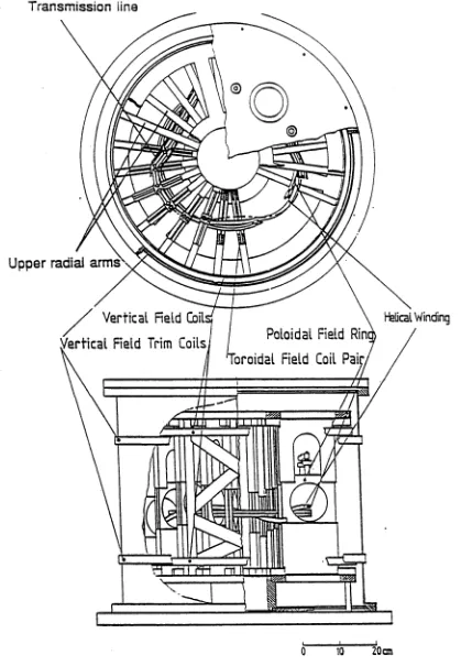
Figure 2.1 shows the construction of the SHEILA heliac. The main magnetic field coils are accommodated inside a stainless-steel vacuum chamber (diameter 0.65 m, height 0.6 m, side-wall thickness 3.25 mm and lid thickness 25 mm). The coils are: a set of 24 toroidal field coils with 11 cm diameter circular apertures, a four- turn toroidally directed ring conductor (radius = 18.75 cm), a helical winding and two sets of vertical field coils with one set inside the vacuum vessel and the other outside.
The 24 toroidal field coils are mounted in such a way that their centers follow an
Transmission line
Upper radial arms
Helical Winding
0 10 20cm
[image:27.555.68.487.76.681.2]I
X o
Ujcs
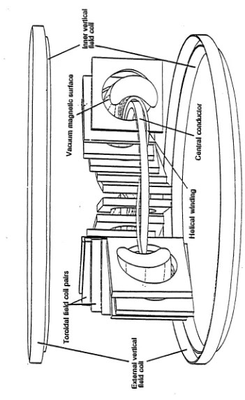
[image:28.555.101.452.91.664.2]With the arrangement of the magnetic field coils described above, the flux surface of SHEILA has a bean-shaped cross-section and twists around the ring conductor along the magnetic field. Figure 2.3 shows a typical ideal vacuum magnetic flux surface and the corresponding magnetic field lines. The flux surfaces cross-section of SHEILA at four different toroidal angles within one field period (<f> = 0,30°, 60° and 90°) are shown in figure 2.4, which are calculated by the HELIAC code [1]. The rotational transform l varies from 1.2 at the magnetic axis to 1.4 at the
outermost flux surface for the SHEILA standard magnetic field configuration, which has no current in the helical winding. This standard geometry is used in all the experiments described in this thesis. The average radius of the last closed flux surface for the standard magnetic field geometry and the major plasma radius are 3.5 cm and 18.75 cm respectively as shown in Table 2.1. The profiles of the rotational transform and the magnetic well depth, and thus the shape of the magnetic flux surface in SHEILA can be varied by adjusting the ratio of the current in the helical coil Ih to that in the ring coils Ir. Detailed descriptions of
a)
b)
[image:30.555.119.419.84.658.2]the SHEILA m agnetic field geom etry as a function of I r / I h are found in references
[2, 3, 4, 5]. For the standard configuration, the m axim um m agnetic well depth
on the last closed surface is about 4.5%.
The availability of the heliac configuration favours the studies of plasm a confine
m ent, stability and equilibrium . M agnetic field m apping experim ents in SHEILA
[6, 7] indicate th a t the m easured m agnetic field flux surfaces are in good agree
m ent with theory. Field errors due to m is-alignm ent of the coils are negligible in
the stan d ard configuration.
2.2.2
A n cillary E quipm ent
Two capacitor banks (2 m F and 5 mF; 10 kV m axim um ) connected via a non-
cored transform er supply a m axim um of 5 kA pulsed electrical current for the
m agnetic field. Peak m agnetic fields of 2.5 kG are available in a pulse duration of
50 ms. However, the device operates very reproducibly when the peak m agnetic
field is below 1.8 kG. The m agnetic field coils are connected in series in order to
m aintain the m agnetic field geom etry as constant as possible during the pulse.
Two variable current shunt resistors are used in the electrical circuit of the m ag
netic field to allow the adjustm ent of the relative currents in the helical winding
and the outer vertical field coils.
T he vacuum tank is evacuated by a two stage rotary pum p with a pum ping speed
of 8.2 1/s and an oil diffusion pum p with a speed of 350 1/s. The base pressure
of th e vacuum vessel is between 10-5 and 10~6 torr. A needle valve controls
th e filling gas pressures, up to 5 x 10⁻³ to rr in these experim ents. Two vacuum
gauges, a Model 275 Convectron gauge and an ionization gauge, are used for
m onitoring gas pressure in a low (> 10~3 torr) and a high (< 10-3 torr) vacuum
respectively.
Since rf power is applied in the experim ent, some radiated rf power may intro
duce rf currents flowing around the m agnetic field coils and th e other supporting
antenna-near-field signal to the magnetic field probes and cause a significant error in the plasma wave field data. In order to suppress the coupling of the rf fields to coils, there are about 30 RC {R=l fb (7=1 nF) series rf snubbers connected between the coils and earth. The rf snubbers reduce the coupling to the coils by about a factor of 10 in the range 1 - 3 0 MHz.
2.3
R a d io F r e q u e n c y S y s te m s for P la s m a For
m a tio n a n d W ave C o u p lin g
2.3.1
In trod u ction
Three different antennas are used in the experiments, an electrostatically shielded half-turn loop antenna, an unshielded partial-turn loop antenna and a double saddle loop antenna, used for both high and low power helicon wave excitation. The electrostatically shielded antenna is used for the study of wave propagation. The other two antennas are primarily used for the comparison of the antenna-wave coupling efficiencies due to different antenna geometries and for understanding of the mechanisms of plasma production by helicon waves. Detailed descriptions of the three antenna and the associated rf systems will be presented in the following subsections.
2.3.2
R F A n ten n as
E lectrically Shielded Half-Turn Loop Antenna. The electrostatically shielded half-turn loop antenna consists of a copper loop of poloidal length 120 mm, axial width 8.5 mm and average radial spacing 4.2 mm, as shown in figure 2.5. The antenna is installed at a 0=75° port in SHEILA and extends for half the poloidal circumference of the local plasma cross section. The shield is made from slotted stainless steel foil and is opaque to plasma along the toroidal magnetic field lines.
Return Conductor
Figure 2.5: A diagram of the electrostatically shielded half-turn loop an tenna used in SHEILA.
(ICRH ) in therm onuclear plasm a experim ents [8, 9, 10, 11]. This antenna pro
[image:33.555.89.484.70.296.2]duces an oscillating m agnetic near-field, parallel to the steady toroidal field lines
[12, 13]. The electrical shield acts to short out th e E\\ com ponent of the wave
field thereby minimizing electrostatic wave excitation in the plasm a periphery.
This should also reduce power losses at the plasm a antenna interface due to the
sheath effect.
The vacuum power spectrum of this type of antenna can be easily analyzed for
an assum ed an ten n a current distribution. The antenna current distribution can
be expressed in a general form as [14],
l a m = I oP( 0) T( z) (2.1)
where 70 is the peak an ten n a current, P{0) is th e poloidal current distribution,
and T( z ) is the toroidal current distribution of the antenna. In the experim ent,
0 otherwise
A constant P(0) accounts for the much shorter physical length of th e antenna
center conductor (12 cm ), com pared with the free-space radio frequency wave
length (> 10 m) for f < 30 MHz. The T(z) function is chosen so th a t th e current
d istribution peaks at the edges of the antenna to approxim ate the redistribution
of current so th a t th e m agnetic com ponent of B norm al to the surface of the
an ten n a strap is zero, and w is the half-width of the central conductor of the
antenna. The functions P(0) and T( z) are plotted in the inset of figure 2.6. For
these distributions the corresponding Fourier com ponents of the current are
sin2 Y
(2f)2
(2.4)|Tm|2 = ± - J 20(kzw) (2.5)
Z7T
Figures 2.6 (a) and (b) plot respectively th e poloidal and toroidal power spectra
of the antenna in a vacuum . It can be seen th a t rf energy is m ainly coupled
into th e m — 0 and m = ± 1 azim uthal eigenmodes by th e antenna. T he w idth
of th e toroidal k\\ spectrum is very broad and peaks at k\\ = 0, corresponding
to an infinite parallel wavelength, with a —3 dB point at fey = 150 m _1. The
radiated power spectra in a plasm a could be very different and will depend on
- 1.0 0
- 1 0 0 0 - 5 0 0 0 5 0 0 1 0 0 0
kll ( m ' 1)
—n / 2 0 n / 2
Poloidal Mode N u m be r m
Figure 2.6: The electrostatically half-turn loop antenna power spectrum for SHEILA, (a) Toroidal power spectrum |Tm|2 versus k z for the assumed toroidal antenna current distribution (inset), (b) Poloidal power spectrum |Pm|2 versus m for the assumed flat current (inset).
The design of this antenna, and the limited space available prevented its use at high power for plasma production. Instead, such experiments were conducted with the two following antennas.
return conductor
center conductor
[image:36.555.78.449.63.267.2]coaxial cable PLA SM A
Figure 2.7: The unshielded partial-turn antenna configuration in SHEILA.
rf power is applied to this antenna, a silver coating protected by Ti-N film has
been used to minim ize rf power dissipation. The unshielded antenna is located
at the 150° port and is fed via a coaxial cable: its center conductor subtends half
th e poloidal peripheries of the plasm a. To lim it the rf plasm a sheath current,
the an ten n a is electrically insulated from the plasm a by about 10 layers of teflon
tap e. Sim ilar current distributions and vacuum radiated power spectra would be
expected for the shielded antenna.
D o u b le -S a d d le L oop A n te n n a . The double-saddle loop antenna [15] is ap
proxim ately 16 cm long and wound from one piece of 3.4 m m diam eter enamelled
copper wire as a double-saddle coil and located outside th e plasm a with the planes
of the two coils being tw isted so as to follow the local field lines of the outerm ost
closed flux surface (figure 2.8). It is situated at port 120° (see figure 2.11) and
connected to th e m atching network through two vacuum feedthroughs. The an
ten n a is electrically floated w ith respect to the SHEILA vacuum cham ber and the
wire is covered w ith 2 - 3 layers of ‘K ap to n 1 tape so as to be properly insulated
from th e plasm a. The excited rf oscillating m agnetic field is m ainly perpendicu
lar to the plasm a axis. The double-saddle loop an ten n a is not only used for the
com parative studies of wave-plasma coupling, but it also plays a m ajor role in
*
♦
Figure 2.8: Basic shape of the double-saddle loop antenna used in the plasma formation in SHEILA.
2.3.3
R adio Frequency E quipm ent
In the wave propagation experiment, a Kenwood TS-440S rf transceiver is used as the rf source. It delivers up to 150 watts power to the electrostatically shielded antenna.
[image:37.555.84.462.38.353.2]Kenwood T S4 4 0 s
if oscillator Kenwood
TL-922
Amplifier
Alpha
77 DX
Amplifier
RF
Directional
Coupler
To antenna
40 : 1
Voltage Divider
Reference Signal
Figure 2.9: Typical arrangement of the rf systems used for wave excitation in the SHEILA plasma.
In the last m onth of the two antenna experim ent, a high power tra n sm itte r (30
kW, 1-30 MHz) [16, 17] was connected to the unshielded half-turn loop antenna to
obtain com parable wave fields to those excited by the double-saddle loop antenna.
A m axim um of 11 kW rf power was delivered into the antenna at 7 MHz.
In the two an ten n a experim ent, investigations of plasm a density m odulation were
m ade by phasing the currents in the two antennas. For this purpose, only one rf
driver is used and its power split via an rf power sp litter shown in figure 2.19. The
two o u tp u ts of th e sp litter were then amplified by the two-stage linear am plihers
as described above. The relative phase between the antennas was altered by
changing the length of transm ission line in one arm of the splitter.
All the rf suppliers m entioned above are operated in pulses of up to 20 ms duration
except where otherwise stated. This pulse is adjusted to be sim ultaneous with
the flat regime of the pulsed m agnetic field. The frequencies of all the rf sources
can be varied in the range ~ 1 - 30 MHz.
Two rf directional couplers, a commercial unit (N arda) and one m ade in this lab
oratory [18], are used in th e experim ents to m onitor th e forward and the reflected
power. These signals are essential for the m easurem ents of antenna loading dis
cussed in section 2.4.4. The calibration factors of the two directional couplers
4
4
current
C2
antenna
i l i
current transformer
Figure 2.10: Principal diagram of the matching circuits used.
power ranges. The sensitivities of the directional couplers against rf frequencies are carefully and absolutely calibrated.
2 .4
D ia g n o s tic s
2 .4 .1 I n tr o d u c t io n
Visible Light
270°detector
Figure 2.11: The top view of SHEILA and the locations of diagnostics and
2 .4 .2 M a g n e tic P r o b e s a n d S ig n a l P r o c e s s in g
Measurements are made using magnetic probes in an attem pt to identify wave numbers of the eigenmodes and to measure radial structures of the waves. There is one three-component probe for a simultaneous measurements of (Br, Be and
Bz) and several probes which measure only one component of the wave fields. Generally, a signal measured by a magnetic probe is given by
V g (2.6)
where n is the number of turns, dp j dt (P =A & ) is the rate of change of wave field flux passing through the area A of the coil with a magnetic field strength
B.
For a sinusoidal rf field, this becomesVb =uA B (2.7)
where u is the angular frequency of the waves, Vb is amplitude. A probe coil may also pick up a signal due to capacitive coupling with the plasma. This electrostatic coupling may seriously affect the quality of the measured wave field data. If the electrostatic pick-up is Vg, then the total signal seen by the probe is V = Vb
+ Vg. Sometimes Vfc is comparable or even greater than Vg, depending on the plasma potential, the coil size and the electrical shielding around the probe. In order to remove the electrostatic component, a hybrid combiner [19, 20] was built and connected to each of the probes to reject the electrical pick-up.
x i
Ql X i
3 15 2
F r e q u en c y (MHz)
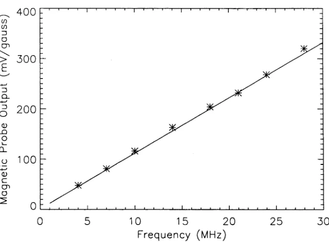
Figure 2.13: An example result of calibrations of magnetic probes by a Helmholtz coil. The measured sensitivity (mV/gauss) of a magnetic probe as a function of rf frequency is shown.
After signal processing by the circuit, a typical output of a magnetic probe as a function of frequency is plotted in figure 2.13. The output was obtained when the probe was calibrated against a Helmholtz coil. According to these results, the probe has a response which is linear in frequency to at least 28 MHz.
[image:43.555.90.412.138.375.2]shielding box
earthed box
coaxial cable potential hole
probe insert
electrical insulation layer
Figure 2.14: Construction of the electrical potential cup used for the ca pacitive pickup test of the magnetic probes.
in a grounded metal box with coaxial signal feeds to reduce interference from signals propagating along the coaxial cable’s outer conductor and to stop such currents penetrating into the measurement circuit in any case. This arrangement corresponds to experimental situations of a probe in plasma. It is also realized from the measurement that the capacitive signal still has some effect on the out put of the magnetic component when using the hybrid combiner. However, the magnetic output (T3)only shows a one-tenth magnitude of the electrical compo nent. This could provide a clue that as long as the magnetic component in the probes is much greater than one-tenth of the the electrical signal, the wave data may still be trustworthy.
In the three-component magnetic probe, each component consists of a 5-turn coil of 0.1 mm diameter enamelled copper wire. Three orthogonal coils are wound on a plastic former perpendicular to each other. Cross-talk due to non-orthogonality amounts to about 7.0% at 18 MHz. The single probes consists of a 20 turn coil made of 0.04 mm diameter copper wire. All these probes have an overall dimension less than 3 mm. This allows good spatial resolution and frequency response. The measured wavelengths in the experiments are much larger than the probe size so that the measured wave fields across the dimensions of the probes can be considered approximately uniform. The coil leads of the probes are twisted and fed through an earthed copper tube to minimize electrical pick-up.
structure of the fields. (Br, Be, B z). One single probe (Bz) is located at the 150° port for an azimuthal scan of B z component of the wavefield. The B z probe can be moved poloidally on magnetic flux surfaces guided by a 2-D manipulator [5]. several other probes were located at various toroidal locations to measure the parallel wavelength. All the probes enter the plasma through glass tubes. These glass tubes are radially movable and have diameters of 6 - 8 mm. This allows a convenient radial scan of the wave fields.
When making an azimuthal scan, it is found that the plasma density decreases significantly when the probe reaches the inner side of the magnetic flux surfaces. The plasma density drops because the glass tube and the shielding intersects a large section of the plasma. The 150° port is very close to the plasma generation antenna at the 120° port. In the discussion of the azimuthal scan measurements to be presented, only the unperturbed data will be provided, which correspond to the data obtained along the low field side part of the flux surface.
In the shielded antenna experiment, a notch filter and a high-pass filter are also used in the probe signal processing after the hybrid combiner. The notch filter suppresses the high power signal at 7 MHz, coming from the plasma generation source (the double-saddle loop antenna). An attenuation of 50 - 60 dB of the signal at 7 MHz is so obtained. The high-pass filter reduces the signal at 100 kHz from the ohmic power to a negligible level. These circuits are shown in figure 2.12.
2 .4 .3 M a g n e t ic P r o b e S ig n a l A n a ly s is S y s te m
signals and a m agnetic probe signal are mixed by two identical mixers (LM 1469
N) which act as signal m ultipliers. The two mixers then produce T sin(0) and
,4cos($) as their outp u ts, with which the phase (0) and the m agnitude of the
probe signal can be obtained. In the circuit, there are two outp u t amplifiers,
one with an upper 3 dB frequency of 10 kHz and the other at 100 kHz. These
two low pass filters filter the o u tp u t to elim inate spurious rf mixer products, can
be selected according to requirem ent. Since several amplifiers are involved, an
approxim ate gain of 19.8 occurs between the input (rf m agnitude) and the ldc'
o u tp u t.
The 90° phase shifter has a significant error over the frequency range 1 - 3 0 MHz
(as much as 22° !). Care is taken to calibrate the detection system and to m easure
0 f o r 7 MHZ
A f o r 2 8 MHZ
) 200 ;
Calculated P h a s e (deg)
the phase error at each frequency (1 - 30 MHz) used in the experiments. These errors are taken into account in data analysis. After calibration, a reasonable agreement between the expected phase produced by varying the length of a coaxial cable and the measured phase is obtained and presented in figure 2.16.
The outputs A sin(0) and A cos(0) of the detection system are connected to a data acquisition system. The DC outputs are digitized by 8212A CAMAC controlled analogue to digital converters with 12 bit resolution. Normally, a 10 kHz clock rate (40 kHz for rf current drive data) is used for the digitization, with the system being triggered just before the rf pulse. A Vax workstation is connected to store and analyze digitized data. IDL (Interactive Data Language) software in conjunction with the MDS data system is used to implement data plotting facilities and data analysis, including calibration of phase and magnitude. Some slow signals, such as the plasma density and the confinement magnetic field, etc. are digitized by a slower digitizer system, CAMAC 8212 with a sampling rate of
2 .4 .4 M e a s u r e m e n t s o f A n t e n n a L o a d in g
In the experiments, the antenna loading is obtained by the following formula
where R in the antenna loading, including the rf power dissipation in the trans mission network, the antenna conductor and the plasma. Pj and Pr are the for ward and reflected power, and / ant is the rms antenna current, which is assumed constant along the length of the antenna in the experiment.
The plasma loading is calculated by
where R v is the antenna loading, measured in vacuum, representing the rf power 5 kHz.
(2.8)
losses. Theoretically the vacuum loading is proportional to \ f ] and it is assumed
not to change in the presence of plasma.
The forward and reflected powers are measured at the input to the m atching
network by a directional coupler. The antenna current is measured by a cur
rent transform er [20] connected to the antenna lead. A schem atic of the current
transform er is shown in figure 2.17.
The antenna current diagnostics consists of two-stages with 27 tu rn current tran s
former encircling the antenna feeder and a 6 tu rn isolation transform er. The 27-
tu rn coil is wound on a toroidal ferrite core with a high perm eability fir and picks
up the m agnetic flux produced by the antenna current. Ri and R2 are current
sensing resistors. The second stage transform er rejects electrostatic coupling to
the windings of the current transform er. The resistors R 3 and R 4 in the circuit
allow an adjustm ent of the overall gain of the current transform er.
From A m pere’s law, the m agnetic field B in th e ferrite core is related to the
current / through the center of the core and the current i in the windings of the
current transform er by
(2.10)
I B d \ = fiQHr{I — ni]
Also the e.m.f. o u tp u t of the transform er is given by
d / B - d A
£ = —n---
---dt
where A is the area of the coil, u; is the angular frequency, d B/dt is the rate of
tim e change of the m agnetic field. Assuming a uniform m agnetic field in the core,
then, e — ntoA B . W hen a resistor R is connected to the o u tp u t, we have V = i R,
where V is the o u tp u t voltage. From the above discussion, the dependence of the
o u tp u t on the antenna current is
/ - n l
R nfio/drUjA V (2.12)
where / is the circum ference of the torus axis, /i0 a n d ^ ^ are the m agnetic per
m eabilities of vacuum and the m edium respectively. It is obvious th a t a fre
quency independent relation between the o u tp u t voltage V and / is obtained if
n 2 Rl /fi0firujA. This is readily satisfied in the experim ental frequency range
w ith properly chosen param eters. One therefore assum e I ~ i N in equation 2.10.
The current transform er has such a high reactance th a t the m agnetic flux gener
ated by the induced current i in the coil cancels th a t produced by the current,
/ .
There are three current transform ers used, one connected to each of the antennas.
T heir calibration factors are 16 A/V, 10 A/V, 20.5 A / V for the double-saddle loop,
the shielded and unshielded antennas respectively. The two directional couplers
described before provide the m easurem ents of the forward and reflected power in
the transm ission lines.
Since the plasm a loading R v may be small, care has been taken to check the
cn
E 5 0 00
7 MHz 4 0 00
3 00 0 2 0 0 0 1000
1000 2 0 0 0 3 00 0 Resistor ( oh ms )
5 00 0 4 0 00
1500
o 1000
5 10 15 20 25
Frequency (MHz)
Figure 2.18: The calibration results of the antenna loadings for the double saddle loop antenna and for the electrostatically shielded antenna are given in (a) and (b) respectively, (a) shows the resistance values derived from the measured loadings as a function of the values of the resistors, (b) plots the derived resistances versus rf frequency while the value of the connected resistor is not changed. For the later case, the calibration was made to two different resistors, 470 ohms and 1000 ohms respectively as indicated in (b).
conductors, and m easuring the antenna loading, then com paring the vacuum
loading and th e loading w ith th e resistor present. It is expected th a t an ex tra
loading AR = (ujL) 2/ r should be added to the vacuum loading Rv, where L is the
an ten n a inductance. Figure 2.18 (a) gives exam ples of good agreem ent between
the resistance values derived from the m easurem ent and the resistor values r
connected to the double-saddle loop antennas.
particularly at high frequency, due to the existence of an approxim ately 90 cm
length of transm ission line between the antenna and the current transform er.
The transm ission line can cause an underestim ation of the antenna current. The
resultant error in the antenna current m easurem ent was calculated at each rf
frequency by solving the transm ission line equation [20] and com pensated in the
d a ta analysis program . Figure 2.18 (b) shows an agreem ent between the con
nected resistor values and th a t derived from the m easurem ent after the effect of
the transm ission line is taken into account.
2 .4 .5 R F P o w e r S p litt e r
In the two an ten n a experim ents, the plasm a is sometim es formed with two an
tennas. A single low level rf oscillation source is used; the signal is split into two
p arts before am plification and delivered to the two antennas.
The rf power sp litter used in the experim ent is simply a 1 : 2 transm ission line
balun. It is a m em ber of a more general class of im pedance transform ing baluns
[25] and works well in the frequency range of 5 - 40 MHz [24]. A diagram of
th e circuit is sketched in figure 2.19. The splitter consists of three coaxial cables
30 cm
(RG 59) with identical length (30 cm) and characteristic im pedance Zo = 75 12,
each wound on a toroidal m agnetic ferrite core to restrict the current flow on
the outside of the coaxial braids. This improves the core frequency performance.
High power operation necessitates the use of many ferrites and high power cable.
As a result, usual 1:2 baluns based on the Ruthroff transm ission line transform er
[26] tend to have non-uniform frequency response as a result of currents being
sum m ed at circuit nodes after unequal phase delays along finite length cable in
the high frequency range. The balun of figure 2.19 avoids this problem by only
sum m ing currents at nodes of equal phase delay. W ith the connection shown in
the figure, an input rf power is split by the system into two outp u ts, and the
input is m atched provided th a t the outp u ts are term in ated correctly (in 5012).
Theoretically, it is found [19, 24], in such an arrangem ent, th a t the im pedance
transform ation (Z tn / Z out) is 4 : 9 regardless of the length of the identical cables.
The input im pedance Z in = 2Zo/3 = 50 12 and the to tal o u tp u t im pedance is
Z 0ut = 9 Zin/ 4 = 112.5 12. In the experim ent, however, the sp litter has an input
im pedance 53 12 m easured, which is close to 50 12, but the m easured total outp u t
im pedances are 100 12. However, these errors do not affect the experim ental
perform ance appreciably.
2 .4 .6 R o g o w s k i C o il
Two Rogowski coils are used in the m easurem ents of th e plasm a currents in
SHEILA. A bean-shaped coil surrounds the last m agnetic flux surface in SHEILA
and m easures th e net currents in the toroidal direction. A small circular coil
provides m easurem ent of profiles of local current density.
The schem atic of the bean-shaped coil is drawn in figure 2.20. The coil consists
of 900 turns of copper wire (0 = 0.1 m m ) wound on a bean-shaped glass tube
1.0 cm in diam eter. The inductance and resistance of th e coil are m easured to
be 286 //H and 20 ohms separately. A one-turn retu rn wire is wound back from
Vout
Rogowski Coil
900-turn coil
([) =10 mm
plasma current
Figure 2.20: Diagram of the bean-shaped Rogowski coil in SHEILA.
changes linking the bean-shaped coil. The sensitivity of the coil is absolutely calibrated by a known pulsed current and is found to be 1.83x10“ ' Vs/A. The calibration data are plotted in figure 2.21, where the upper curve is the pulsed current fixed at 1.0 A and the bottom curve is the coil output.
The coil is totally covered by insulating teflon tape and is then painted in ceramic to avoid any current conduction to the plasma. The coil is situated at the 240° port.
The vertical and helical fields may induce very large signals on the output of the coil. To subtract the signals, another Rogowski coil is connected to the main power supply circuit, which introduces a signal with opposite sign but the same amplitude to subtract the noise signal. The signal is decreased to a small level by a 20 : 1 voltage divider before being used for the subtraction.
^ 0. 8
- 0.2 - 0.4 - 0.6
0.000 0.010 0 .020 0.030 0.040
Time (ms)
Figure 2.21: The output (b) of the bean-shaped Rogowski coil when a pulsed current (a) passes through the coil.
toroidal direction. This induced e. m. f. will drive a toroidal current in the plasma. It is found, however, that the e. m. f. is approximately 40 //V during the period of plasma duration, much too low to drive a current in the ampere range in the resistive plasma. To drive such a current, a toroidal electrical field of 0.1 V/m is necessary in most experimental conditions. In fact, we do not see any change in the measured current direction when we vary the timing of plasma pulse between the rise to the decay of the confinement magnetic field B0, even though the e. m. f. changes its direction in the plasma.
reac-tive part, X (= jcoL), or X / R <C 1, where X and L are the reactance and the
inductance of the coil respectively. In this case, the coil o u tp u t would have a fast
response to the passing current and gives a signal proportional to the derivative
of the pulsed current. The voltage o u tp u t can be w ritten as [23],
v/ = <i> = ü M /
where $ is the m agnetic flux enclosed in the cross section area A of the coil, / is
the periphery of A, n is the num ber of turns in the coil and /i is the m agnetic
perm eability, equal to the vacuum perm eability fiQ in this experim ent.
The round Rogowski coil is built in the exact same way as th a t for the bean
shaped coil. The differences are th a t its size is sm aller (toroidal radius 13 mm,
poloidal radius 3.2 m m ) and the num ber of the coil tu rn s is 340, so th a t it is less
sensitive than the bean-shaped coil. The coil is inserted in either the 30° port or
the 210° port to confirm th a t the current is circulating.
2.4.7
L angm uir P rob es
M easurem ents of th e plasm a density and electron tem p eratu re are m ade using a
Langm uir probe. The construction of the probe is show in figure 2.22. The probe
is m ade from a 1 m m diam eter tungsten wire enclosed in a thin-walled silica tube.
Only th e 2 m m long tip of the tungsten wire is exposed to the plasm a. The silica
tu b e has a funnel shape near the tip of the probe intended to restrict pollution
of the tip by sp u ttered m etal particles. The probe is located at th e 0° port and
accesses to the plasm a through a sliding O-ring seal. This allows m easurem ents
of radial profile of density and tem p eratu re.
For density m easurem ent, the probe is biased to a large negative voltage (i.e.
Vb ~ —135 V) so th a t only ions are a ttra c te d to the probe and the measured
current saturates. The ion satu ratio n current corresponds to a m easurem ent of