Int. J. Electrochem. Sci., 4 (2009) 1289 - 1301
International Journal of
ELECTROCHEMICAL
SCIENCE
www.electrochemsci.org
Synthesis of Polythiophene Nanoparticles by Surfactant
-Assisted Dilute Polymerization Method for High Performance
Redox Supercapacitors
S. Richard Prabhu Gnanakan, M. Rajasekhar and A. Subramania* Advanced Materials Research Lab, Department of Industrial Chemistry, Alagappa University. Karaikudi – 630 003, India.
*E-mail: [email protected]
Received: 4 July 2009 / Accepted: 15 September 2009 / Published: 30 Setember 2009
Polythiophene (PTh) nanoparticles was synthesized by cationic surfactant assisted dilute polymerization method using FeCl3 as oxidant to use as electrode material for high performances
redox supercapacitors. The physical characterizations of the synthesized PTh nanoparticles were studied by FT-IR and UV-Visible spectroscopy, XRD, SEM and electrical conductivity studies. The synthesized PTh nanoparticles were used for the first time to fabricate symmetric type redox supercapacitor and its capacitor performances were studied by cyclic voltammetry, impedance spectroscopy and charge-discharge studies. The specific capacitance of the capacitor was found to be 134 Fg-1. The energy and power densities were calculated as 8 Whkg-1 and 396 Wkg-1, respectively. It was found that the PTh obtained by cationic surfactant assisted dilute polymerization method had better capacitor performances than the same obtained by the conventional chemical and electrochemical polymerization methods.
Keywords: polythiophene, supercapacitors, surfactant assisted dilute polymerization method, cyclic voltammetry, specific capacitance.
1. INTRODUCTION
Supercapacitors or electrochemical capacitors have gained a great attention in recent years because of their potential applications ranging from cellular phones to electric vehicles. The possibility to use these systems to power hybrid electric vehicles (HEVs), camera flash bulbs, pulsed lasers, or any other device that requires a large amount of charge delivered in a very short time could be realized with supercapacitors [1].
been involved for the development of supercapacitors using conducting polymers based electrode materials, such as polyaniline (PANI), polypyrrole (PPy) and polythiophene (PTh), etc [5-10]. Among these conducting polymers, polythiophene has been much interested due to its environmental stability, high electrical conductivity, and its applications [11, 12]. The stability of PTh in the oxidized form, its high conductivity and an interesting electrochemical behavior allow this material to use as electrode materials for electrochemical supercapacitors.
Depending on the characteristics of starting monomer, different preparative methodologies have been adopted to obtain the polymeric materials. They are classified into two major methods, such as electrochemical and chemical polymerization methods. The chemical oxidative polymerization is more applicable than electrochemical method for the preparation of bulk electrode materials with controllable sizes. The materials in nano-size have high surface area with uniform porosity gives better supercapacitor performances [13-15].
Hence, in the present investigation, polythiophene nanoparticles was prepared by cationic surfactant assisted dilute polymerization method and used for the first time to use as electrode material for symmetric type redox supercapacitors. The synthesized PTh nanoparticles were characterized by FT-IR, UV-Visible spectroscopy, XRD, SEM and electrical conductivity studies. The symmetric type redox supercapacitor was fabricated and its capacitor performances were studied by cyclic voltammetry, impedance and charge-discharge studies. Finally, the PTh nanoparticles obtained by cationic surfactant assisted dilute polymerization method was compared with the same obtained by the conventional chemical and electrochemical polymerization methods.
2. EXPERIMENTAL PART 2.1. Materials
Reagent grade thiophene (Merk), ferric chloride (CDH), N-cetyl-N,N,N-trimethylammonium bromide (Aldrich), multi walled carbon nanotubes (MWCNTs) (Aldrich), poly(vinylidenefluoride) (Aldrich), lithium hexaflourophosphate (CDH), poly(vinylidenefluoride-co-hexaflouropropylene) (Aldrich), ethylene carbonate (Alfa-Aesar) and propylene carbonate (Alfa-Aesar) were used as received.
2.2. Preparation of polythiophene nanoparticles
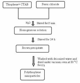
surfactant (CTAB) were dissolved in 30 ml of distilled water by constant stirring for 15 min. The oxidant, such as 0.055 mol of FeCl3 solution was added dropwise to the monomer-surfactant solution
under stirred condition [16]. The preliminary polymerization process was identified by the colour change (brown) of the reaction mixture. The polymerization process was allowed to constant stirring for 24 h at 30 oC. The dark-brown precipitate of polythiophene was collected by filtration of the
reaction mixture using methanol and distilled water until colourless filtrate was obtained. The obtained PTh nanopowder was dried in a vacuum oven at 80 °C for 6 h. The flow chart and reaction scheme for the preparation of polythiophene are shown as Figure 1. (a & b).
2.3. Preparation of composite electrodes
The composite electrodes were prepared by mixing of active material, conducting additive and binder material. The PTh nanoparticles was used as major electrode material (85 wt%), multi walled carbon nanotubes (10 wt%) as conducting material and poly(vinylidenefluoride) (5 wt%) used as binder were mixed well using N-methylpyrrolidone solvent and made into a slurry. The polymer slurry was coated about 1×1 cm2 area on 5×1 cm2 stainless steel foil current collector. The electrode was dried in vacuum oven at 80 °C for 12 h [17].
[image:3.612.171.441.368.648.2]Figure 1(b). Scheme of the reaction for the polythiophene nanoparticles synthesis.
2.4. Preparation of microporous polymer electrolyte membrane
The appropriate amount of PVdF-co-HFP polymer was dissolved in dimethyl formamide (DMF) solvent. To this 20 wt % of fumed silica was dispersed and made into uniform viscous solution by stirring. This viscous solution was poured on a glass plate and uniformly spread with the thickness of 50 ± 5 µm by means of a doctor blade. This film was dried in a dust-free atmosphere at room
temperature for 6 h. The dried film was immersed in hydrofluoric acid to dissolve the silica (filler) to get microporous polymer film. Further drying was performed in a vacuum oven at 80 oC for 12 h. This
microporous polymer film was then socked in 1M-LiPF6 containing 1:1 v/v EC/PC electrolyte solution
for about 24 h. The obtained microporous polymer electrolyte membrane was used to construct the symmetric type redox supercapacitor.
2.5. Unit cell fabrication
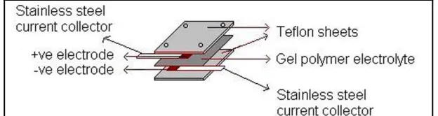
The structure of all-solid supercapacitor using PTh and PVdF-co-HFP based microporous polymer electrolyte is shown as Figure 2. Each active electrode area was maintained as 1×1 cm2 for the
[image:4.612.172.419.93.144.2]fabrication of a unit cell. The area of electrolyte membrane was twice the area of electrode was sandwiched in between the electrodes and then tightened well using teflon sheets with screws. This minimized the ohmic resistance and established a good contact between the electrodes and the polymer electrolyte membrane. This polymer electrolyte membrane acts both as a separator as well as electrolyte.
[image:4.612.150.462.570.653.2]
2.6. Characterization
The synthesized PTh nanopowder was analyzed by Perkin Elmer- FT-IR spectroscopy (Model-1600). Absorption spectrum of the PTh sample was recorded at ambient temperature by Shimadzu-UV-Visible spectroscopy (Model-2401 PC). X-ray diffraction study was carried out by JEOL X-ray diffractometer (Model- JDX 8030) using nickel-filtered Cu-Kα radiation of wavelength 1.54 Å and
continuous scan speed of 0.045o min-1 for knowing the phase purity and crystallinity nature of the
polymer. The SEM analysis was carried out by JEOL (Model- 840A) scanning electron microscope for knowing the particle nature and size of the polymer powder.
Electrical conductivity of the synthesized polymer was measured by means of four probe technique. The PTh pellet was obtained by pressing the polymer sample into disk of 16 mm diameter and ca. 2 mm thickness under a pressure of 400 MPa. Conductivity was calculated based on the average of at least three pairs of consistent readings at different points on the pressed pellet. All the measurements were done in air at 30 oC and converted into conductivity from the following equation;
σ(S cm)=1 R×
(
l A)
(1)where σ is the electrical conductivity, A is the area of the pellet, l is the thickness of the pellet and R is
the bulk resistance.
The capacitor performances were characterized by means of cyclic voltammetry (CV), impedance measurements and galvanostatic charge-discharge studies. The cyclic voltammetry studies were carried out by Bio analytical system (BAS-100W) at the scan rates of 5, 10, 25, 50 and 100 mVs-1 and the impedance analysis was carried out by EG & G Electrochemical analyzer in the frequency range of 100 kHz to 10 mHz. The charge-discharge performance of the capacitor was studied galvanostatically at constant current density of 1 mAcm-2 by WonATech cycler tester.
3. RESULTS AND DISCUSSION
Figure 3. FTIR spectrum of polythiophene nanoparticles.
The UV-Visible spectrum of polythiophene was recorded after dissolving it in dimethyl sulphoxide (DMSO), is shown in Figure 4. The main charge carriers in polythiophene were polarons and bipolarons [21]. A new broad absorption band related to bipolaron states appeared around 730-890 nm. The absorption bands were obtained approximately at 306 and 377 nm. The band at 306 nm was associated with π-π* inter band transition and band 377 nm was associated with n-π* transition.
Increasing the degree of polymer resulted in a blue shift of λmax, confirmed a shorter conjugation length
of the polymer [22].
Figure 4. UV-Visible spectrum of polythiophene nanoparticles.
diffraction peak associated with the chain–to-chain stacking distance of about 2θ = 22.2° is due to the
amorphously packed polythiophene main chain [23, 24].
The SEM image of polythiophene nanopowder is shown as Figure 6. The image seems to be uniform microporous on the surface and the particles were in nanometer scale. The average particle size of polythiophene was found to be in the range of ~ 25 - 45 nm. This is more useful to electrolyte penetration for charge-discharge process of redox supercapacitor. The electrical conductivity of the pressed polymer pellet was examined by four probe conductivity method, and it was found to be 0.67 Scm-1. This value is higher than the same obtained by electrochemical method [25].
The redox supercapacitor was constructed by polythiophene nanoparticles based symmetric electrodes with PVdF-co-HFP based microporous polymer electrolyte containing 1M LiPF6 in EC/PC
(1:1 v/v). The scanning was performed in the voltage range of –1.0 to +1.0 V at various scan rates of 5, 10, 25, 50 and 100mVs-1 for the capacitor cell (Figure 7). The specific capacitance of the capacitor cell
was calculated at the scan rates of 5, 10, 25, 50 and 100 mVs-1 and they were approximately 134, 93, 54, 39 and 28 Fg-1, respectively. The rectangular form of the voltammogram in which current quickly reached
Figure 5. X-ray diffractogram of PTh nanoparticles.
of current would reduce the potential difference resulting from the ohmic resistance between the surface and bottom of the micropores. The potential difference intensified the lag of charge or discharge at the bottom of the micropores and thus enhanced the delay of current to reach a horizontal value in the voltammogram. To investigate the cyclic stability of the system, cyclings (1000 cycles) were carried out at the scan rate of 50 mVs-1 are shown as Figure 8. The decaying of current was
observed in minimum between 5th and 1000th cycles. This ensures the small capacitance fading of the
electrode material and hence the stability of the electrode material was almost moderate.
Figure 7. Cyclic voltammograms of PTh / PVdF-co-HFP-1M LiPF6 in EC & PC (1:1 v/v) / PTh at the
sweep rates of a) 5 mVs-1 b) 10 mVs-1 c) 25 mVs-1 d) 50 mVs-1 and e) 100 mVs-1.
Figure 8. Cyclic voltammograms of PTh / PVdF-co-HFP-1M LiPF6 in EC & PC (1:1v/v) / PTh at the
The specific capacitance decreased significantly with increasing scan rate upto 50 mV/s (Figure 9.) is due to the resistance of the system. This caused a delay in time to discharge the capacitor [18]. The exact time required to discharge the capacitor depended on the resistance (R) and the capacitance (C) in the discharging system. Above 50 mVs-1, the decreasing of specific discharge capacitance was
not so pronounced. The porous structure on the composite allowed a higher swelling of PTh by the electrolyte solution and the formation of parallel ionic and electronic conduction paths. This phenomenon also contributed to maintain the capacitive nature of the composite, despite the increase in scan rate. The charging currents for both the anode (Ia) and cathode (Ic) increased with scan rate.
The difference between Ia and Ic at current plateaus of the cyclic voltammogram was designed as
charging current (∆I=Ia-Ic) and it was plotted against scan rate (Figure 10.). The capacitance and
faradaic current were obtained from the slope and intercept of the graph between ∆I vs scan rate and
they were 23 mF and 0.62 mA, respectively.
Figure 9. Specific capacitance as a function of scan rate for PTh / PVdF-co-HFP-1M LiPF6 in EC &
PC (1:1 v/v) / PTh supercapacitor.
Figure 10. Capacitive current as a function of scan rates for PTh / PVdF-co-HFP-1M LiPF6 in EC &
frequency impedance associated with the bulk electrolyte resistance and this value was 19 Ω and the
mid frequency of spectrum revealed the electrode/electrolyte interface processes. The charged state of impedance response showed the interface affected state, which was caused by diffusion problems indicated by the increase in the internal resistance. The non-vertical slope of the impedance plot at low frequency of electrochemical capacitor was due to: 1) the microporosity and redox properties of polythiophene; 2) the low mobility of the ions inside the electrode or the combination of both. The decrease in charge transfer resistance with increasing double layer capacitance confirmed that the redox capacitor using PVdF-co-HFP based microporous polymer electrolyte had good cycle life and low self discharge time (time constant). The charge transfer resistance of the cell was found to be 2.2 Ω and the specific capacitance was calculated from the impedance spectrum at 10 mHz and it was 124 Fg-1.
Figure 11. Impedance spectrum of PTh / PVdF-co-HFP-1M LiPF6 in EC & PC (1:1 v/v) /PTh
supercapacitor.
Galvanostatic charge-discharge experiment was performed to PTh based symmetric redox supercapacitor. The PVdF-co-HFP based microporous polymer electrolyte containing 1M LiPF6 in
[image:10.612.190.425.339.528.2]
potential, the total impedance of the cell gave rise to an initial ohmic drop of the discharge voltage which remained till constant capacitive performances were achieved. However, the initial decrease in capacitance was related to the irreversible charge compensation in faradaic reaction associated with the oxidation/reduction of PTh. The initial sharp change in potential with time, during charging and discharging process was due to the ohmic loss which arose from the internal resistance of the cell. The pseudocapacitance displayed a typical charge/discharge performance with small discharge capacitance at the working voltage of 2.0 V. The power density was evaluated by dividing the energy density by discharge time [29]. To avoid IR drop effect in the discharge capacitance, the slope was calculated after the IR drop portion of discharge curve. The capacitance obtained from AC impedance measurements was lower than charge-discharge measurements, as it was measured at zero potential of charge and the potential amplitude was also very small (5-10 mV). This is mainly due to the diffusion of ions in the microporous polymer electrolyte. The values of the discharge capacitance (Cm) and
internal resistance (Ri) of the capacitor were found to be 130 Fg-1 and 10.2 Ω cm2, respectively. The
values of energy and power densities of the capacitors were found to be 8 Whkg-1 and 396 Wkg-1, respectively. In these curves after initial drop in capacity over the first 500 cycles, there was a slow deterioration in the performance during the cycle period and over 1000 of continuous cycles. The device provided up to 94 % of the initial capacitance after 1000 cycles (Figure 13.). The coulombic efficiency is the ratio of charging time to the discharging time. This important parameter was associated with charge/discharge behaviour of the supercapacitors. The coulombic efficiency and the internal resistance as the function of the cycle number are shown as Figure 14. The internal resistance increased with cycle number and the coulombic efficiency was found to be 94 %. From the above studies, it was found that the PTh nanoparticles obtained by cationic surfactant assisted dilute polymerization method had better capacitor performances than the same obtained by conventional chemical and electrochemical polymerization methods [10, 30].
Figure 12. Charge and discharge curves of PTh / PVdF-co-HFP-1M LiPF6 in EC & PC (1:1 v/v) / PTh
Figure 13. Discharge capacitance as a function of cycle number for PTh / PVdF-co-HFP- 1M LiPF6 in
EC & PC (1:1 v/v) / PTh supercapacitor.
Figure 14. Columbic efficiency and internal resistance as a function of cycle number for PTh / PVdF-co-HFP-1M LiPF6 in EC & PC (1:1 v/v) / PTh supercapacitor.
4. CONCLUSIONS
Polythiophene nanoparticles was synthesized by cationic surfactant assisted dilute polymerization method. The polymer nanoparticles was used as electrode materials for symmetric type high performance redox supercapacitor studies with PVdF-co-HFP based microporous polymer electrolyte containing 1M LiPF6 in 1:1 EC/PC electrolyte. Its specific capacitance was found to be 134
Fg-1. This capacitance was decreased slowly on continuous cycling, due to both polymer degradation
ACKNOWLEDGEMENTS
One of the authors M.R gratefully acknowledge UGC, New Delhi, for the financial support under FIP scheme.
References
1. B.E. Conway, Electrochemical Capacitors: Scientific Fundamentals and Technical Applications, Kluwer Academic/Plenum Publishers, New York, 1999.
2. T. Morimoto, K. Hiratsuka, Y. Sanada, K. Kurihara, J. Power Sources 60 (1996) 239.
3. A.G. Rinzler, J. Liu, H. Dai, P. Nickolaev, C.B. Huffman, P.J. Boul, A. H. Lu, D. Heymann, A.M. Rao, Appl. Phys. A 67 (1998) 29.
4. R.H. Baughman, C. Cui, A.A. Zakhidov, Z. Iqbal, J.N. Barisci, G.M. Spinks, G.G. Wallace, A. Mazzaldi, S. Roth, M. Kertesz, Science 284 (1999) 1340.
5. K.S. Ryu, K.M. Kim, Nam-Gyu Park, Yong Joon Park, S.H. Chang, J. Power Sources 103 (2002) 305.
6. P. Sivaraman, V.R. Hande, V.S. Mishra, Ch. Srinivasa Rao, A.B. Samui, J. Power Sources 124 (2003) 351.
7. K. Jurewicz, S. Delpeux, V. Bertagna, F. Beguin, E. Frackowiak, Chemical Physics Letters 347 (2001) 36.
8. Kun Ae Noh, Dong-Won Kim, C.S. Jin, K.H. Shin, J.H. Kim, J.M. Ko, J. Power Sources 124 (2003) 593.
9. C. Arbizzani, M.C. Gallazzi, M. Mastragostino, M. Rossi, F. Soavi, Electrochem. Commun. 3 (2001) 16.
10.D. Krishna Bhat, M. Selva Kumar, J. Mater Sci. 42 (2007) 8158.
11.A. Laforgue, P. Simon, C. Sarrazin, J.F. Fauvarque, J. Power Sources 80 (1999) 142. 12.M. Mastragostino, C. Arbizzani, F. Sovai, J. Power Sources 97-98 (2001) 812. 13.V. Gupta, N. Miura, J. Power Sources 157 (2006) 616.
14.K. Jurewicz, S. Delpeux, V. Bertagna, F. Beguin, E. Frackowiak, Chem. Phys. Lett. 347 (2001) 36. 15.V. Gupta, N. Miura, Electrochem. Commun. 7 (2005) 995.
16.Weikuan Li, Juan Chen, J. Zhang, J. Zhu, Mater. Leters 59 (2005) 800.
17.Jong-Huy Kim, Ashok K. Sharma, Yong-Sung Lee, Mater. Letters 60 (2006) 1697. 18.K.I. Seo, IJ. Chung, Polymer 41 (12) 4491.
19.F. Tran-Van, S. Garreau, G. Lourn, G. Froyer, C. Chevrot, J. Mater. Sci. 11 (2001) 1378. 20.M. Vijayan, D.C. Trivedi, Synth. Metals 107 (1999) 57.
21.Wasim Alhalasah, Rudolf Holze, J. Solid State Electrochem. 11 (2007) 1605. 22.Y.A. Udum, K. Pekmez, A. Yildiz, Synth. Metals 142 (2004) 7.
23.J. Mardalen, HJ. Fell, EJ. Samuelsen, E. Bakken, PHJ. Carlsen, MR. Anderson Macromol. Chem. Phys. 196 (1995) 553.
24.J. Mardalen, EJ. Samuelsen, PH. Carlsen, Synth. Metals 48 (1992) 363.
25.Bekir Sari, Muzaffer Talu, Fati Yildirim, E. Kursad Balci, Appl. Surface Science 205 2003) 27. 26.J. Gamby, P.L. Taberna, P.Simon, J.F. Fauvarque, M. Chesneau, J. Power Sources 101 (2001) 109. 27.D. Qu. H. Shi, J. Power Sources 74 (1998) 99.
28.K.H. An, W.S. Kim, Y.S. Park, J.M. Moon, Adv. Func. Materials 11 (2001) 387. 29.C. Arbizzani, M. Mastragostino, F. Sovai, J. Power Sources 100 (2001) 164. 30.M. Selva Kumar, D. Krishna Bhat,. J. Appl. Polym. Sci. 107 (2008) 2165.