STUDY OF VORTEX TUBE COOLING SYSTEM ON
TOOL WEAR AND SURFACE ROUGHNESS USING
CONVENTIONAL MACHINE
NORAZILAH BINTI MAHMUD
B051310175
STUDY OF VORTEX TUBE COOLING SYSTEM ON TOOL WEAR
AND SURFACE ROUGHNESS USING CONVENTIONAL MACHINE
This report is submitted in accordance with requirement of the University Teknikal Malaysia Melaka (UTeM) for Bachelor Degree of Manufacturing Engineering
(Engineering Process) (Hons.)
by
NORAILAH BINTI MAHMUD B051310174
940201-12-6444
Disahkan oleh:
_____________________________ ______________________________ Alamat Tetap: Cop Rasmi:
C56 PHASE 6, TAMAN PELANGI, 91308 SEMPORNA SABAH.
Tarikh: _______________________ Tarikh: _______________________
*Jika Laporan PSM ini SULIT atau TERHAD, sila lampirkan surat daripada pihak berkuasa/organisasi berkenaan dengan menyatakan sekali sebab dan tempoh laporan PSM ini perlu dikelaskan sebagai SULIT atau TERHAD.
UNIVERSITI TEKNIKAL MALAYSIA MELAKA
BORANG PENGESAHAN STATUS LAPORAN PROJEK SARJANA MUDA
Tajuk: STUDY OF VORTEX TUBE COOLING SYSTEM ON TOOL WEAR AND SURFACE ROUGHNESS USING CONVENTIONAL MACHINE
Sesi Pengajian: 2016/2017 Semester 2
Saya NORAZILAH BINTI MAHMUD (9410201-12-6444)
mengaku membenarkan Laporan Projek Sarjana Muda (PSM) ini disimpan di Perpustakaan Universiti Teknikal Malaysia Melaka (UTeM) dengan syarat-syarat kegunaan seperti berikut:
1. Laporan PSM adalah hak milik Universiti Teknikal Malaysia Melaka dan penulis.
2. Perpustakaan Universiti Teknikal Malaysia Melaka dibenarkan membuat salinan
untuk tujuan pengajian sahaja dengan izin penulis.
3. Perpustakaan dibenarkan membuat salinan laporan PSM ini sebagai bahan
pertukaran antara institusi pengajian tinggi.
4. *Sila tandakan (√)
(Mengandungi maklumat yang berdarjah keselamatan atau kepentingan Malaysiasebagaimana yang termaktub dalam AKTA RAHSIA RASMI 1972)
(Mengandungi maklumat TERHAD yang telah ditentukan oleh organisasi/ badan di mana penyelidikan dijalankan)
SULIT
TERHAD
DECLARATION
I hereby, declared this report entitled “Study of Vortex Tube Cooling System on Tool Wear and Surface Roughness Using Conventional Machine” is the result of my own research except as cited in references.
Signature : ………
Author’s Name : NORAZILAH BINTI MAHMUD
APPROVAL
This report is submitted to the Faculty of Manufacturing Engineering of Universiti Teknikal Malaysia Melaka as a partial fulfilment of the requirement for degree of Bachelor
of Manufacturing Engineering (Engineering Process) (Hons). The members of the supervisory committee are as follow:
………... Supervisor
(Dr. Mohd Shukor Bin Salleh)
………... Co-supervisor
i
ABSTRAK
Vortex Tiub merupakan satu alat penyejuk yang digunakan untuk menurunkan suhu pada zon process pemotongan berlaku. Untuk mengatasi masalah pencemaran alam yang berlaku akibat penggunaan ceceair penyejuk, Vortex Tiub merupakan cara yang terbaik untuk mengatasi masalah ini berlaku. Selain itu, kos penggunaan untuk cecair penyejuk memakan banyak perbelanjaan. Tambahan pula, alat ini tidak menggunakan sebarang bahagian yang bergerak and mudah digunakan. Objektif eksperiment ialah mengenal pasti independen dan dependen parameter yang mempengaruhi kehausan mata alat dan kekasaran permukaan apabila mengunakan vorteks tiub sebagai sistem penyejuk. Selain itu, analisis perubahan secara statistik diantara kelajuan pemotongan, kadar suapan, jenis penyejuk berlawanan dengan kehausan mata alat dan kekasaran permukaan. Objektif terakhir untuk mengetahui optimum parameter untuk mengurangkan kadar kehausan mata alat dan kekasaran permukaan. Eksperiment di jalankan menggunakan milling process dan
keluli D2 sebagai bahan kerja. Data di analisis menggunakan “Design Expert”. Secara
ii
ABSTRACT
iii
DEDICATION
iv
ACKNOWLEDGEMENT
v
TABLE OF CONTENT
ABSTRAK i
ABSTRACT ii
DEDICATION iii
ACKNOWLEDGEMENT iv
TABLE OF CONTENT v
LIST OF TABLES ix
LIST OF FIGURES x
LIST ABBREVIATIONS, SYMBOL AND NANOMENCALTURES xiii
CHAPTER 1: INTRODUCTION
1.1 Research Background 1
1.1.1 Vortex Tube Cooling System 1
1.1.2 Vortex Tube Application in CNC Machining 3
1.2 Problem Statement 6
1.3 Objective 8
vi CHAPTER 2: LITERARTURE REVIEW
2.1 Vortex Tube Cooling System 9
2.2.1 Principle of Vortex Tube Cooling System 9
2.2 Tool Wear 11
2.3 Surface roughness 16
2.4 Type of Coolant 20
2.4.1 Vortex Tube System Cooling 20
2.4.1.1 Counter-flow Vortex Tube 20
2.5.1.2 Uni-flow Vortex Tube 21
2.4.1.3 Conical Vortex Tube 22
2.4.1.4 Double-Circuit vortex tube 22
2.4.1.5 Two-stage vortex tube. 23
2.4.2 Liquid Coolant 24
2.5.2.1 Soluble Oils 24
2.5.2.2 Synthetic oils 24
2.5.2.3 Semi-synthetic Coolant. 25
2.5.2.4 Straight cutting oils or neat oils. 25
CHAPTER 3: METHODOLOGY
3.1 Introduction 26
3.2 Flow of the project 27
3.3 Identify the Variables 28
vii
3.3.1.1 Feed rate 28
3.3.1.2 Cutting Speed 28
3.3.1.3 Type of Coolant 29
3.3.2 Dependent parameters 30
3.3.2.1 Tool Wear 30
3.3.2.2 Stereo Microscope 33
3.3.2.3 Tool Maker Microscope 34
3.3.2.4 Surface roughness 34
3.3.2.5 Profilometer 35
3.4. Design an experiment 36
3.4.1 Milling Conventional Machine 36
3.4.2 Workpiece. 37
3.4.3 Milling Process (Facing) 37
3.4.4 Tool Material 39
3.4.5 Design of experiment (2-Factorial) 39
CHAPTER 4: RESULT AND DISCUSSION
4.1. Introduction 41
4.2 Quantitative Analysis 41
4.2.1 Result 42
4.2.2 ANOVA 43
4.2.2.1 Surface Roughness 43
4.2.2.2 Tool Wear 45
viii
4.2.3.1 Perturbation for surface roughness 46
4.2.4 Optimization 47
4.2.5 Validation 48
4.2.5 Data Analysis 48
4.3 Qualitative Analysis 49
4.3.1 Tool Wear Analysis 50
4.3.2 Chip Analysis 58
4.3.3 Analysis of workpiece surface 62
CHAPTER 5: CONCLUSION AND RECOMMENDATION
5.1 Conclusion 64
5.2 Future Work 65
5.3 Sustainability 66
References
ix
LIST OF TABLES
3.1 The parameter of experiment using design expert 39
4.1 The result for experiment 41
4.2 Analysis of variance table for Surface Roughness 41
4.3 ANOVA (Surface Roughness) 42
4.4 Final Equation in Terms of Coded Factors 42
4.5 Final Equation in Terms of Actual Factors 43
4.6 Analysis of variance table for tool wear 43
4.7 ANOVA (Tool Wear) 44
4.8 Optimization data 46
x
LIST OF FIGURES
1.1 The basic construction of Ranque-Hilsch Vortex Tube,
(Exair Cooperation, 2013).
2
1.2 Cooling Molded Fuel Tank (Exair Cooperation, 2002) 3
1.3 The application of Vortex tube for cooling small parts after brazing, (Exair cooperation, 2002).
4
1.4 The application of Vortex tube for cooling an ultrasonic weld,
(Exair Cooperation, 2002).
5
2.1 Separation of compressed air into hot and cold stream(A.U. Patwari et. al., 2015)
10
2.2 Graph show between the tool wear and cutting time using different type of coolant (Yalcin et. al., 2007).
11
2.3 Show the SEM photographs for flank wear using air coolant during milling operation (Yalcin et. al., 2007).
12
2.4 SEM photographs show the flank wear using fluid coolant during milling operation (Yalcin et. al., 2007).
12
2.5 Show the SEM photography for built-up edge using dry milling tool (Yalcin et. al., 2007).
13
2.6 SEM photographs show the tool flank wear using dry milling (Yalcin et. al., 2007).
13
2.7 SEM photographs show the built-up edge using air coolant tools (Yalcin et. al., 2007).
14
2. 8 The graphs show the variation between the workpiece surface roughness with different types of coolant (Yalcin et. al., 2007).
14
2.9 Shows the graph variation between types of coolant, feed rate and rotational speed, a) 500 rpm, b) 750 rpm, c) 1000 rpm
(Patwari et al., 2015).
xi
2.10 Show the variation of surface roughness and feed rate using different type of coolant, a) 5 mm/min, b) 10 mm/min, c) 15 mm/min
(Patwari et al., 2015).
18
2.11 The structure of airflow counter-flow vortex tube. 20
2.12 The structure of uni-flow vortex tube (Xue, 2012) 20
2.13 Structure of a conical vortex tube (Xue, 2012) 21
2.14 Structure of the Double- Circuit vortex tube (Xue, 2012) 22
3.1 Flow of the project 26
3.2 Frigid-X Sub-Zero Vortex Tool Cooling Mist System (Nex-flow Cooperation).
29
3.3 Wear on end milling cutters and slot drills. 30
3.4 The position of uniform flank wear 31
3.5 The position non-uniform flank wear 31
3.6 The position of localized flank wear. 32
3.7 Position of flank wear land on the drill (Dolinsek et al., 2001) 32
3.8 Stereomicroscope device. 33
3.9 Toolmaker Microscope 34
3.10 The Surftest SJ-301 profilometer 35
3.11 The Vertical Milling Machine 37
3.12 D2 steel workpiece 37
3.13 Carbide Insert 38
4.1 The perturbation graph using Design Expert 45
4.2 Graph of surface roughness 47
4.3 The graph of tool wear 48
4.4 Insert of experiment 1 50
4.5 Insert of experiment 2 51
4.6 Insert of experiment 3 52
4.7 Insert of experiment 4 53
4.8 Insert of experiment 5 54
xii
4.11 Insert of experiment 8 56
4.12 The pattern of chip for all experiment 60
4.13 The surface of D2 steel workpiece using two different types of
xiii
LIST OF ABBREVIATIONS, SYMBOLS AND
NOMENCULTURE
ANOVA - Analysis of variance
oC
- Degree Celsius
COP - Coefficient of performance
DOE - Design of Experiment
oF - Degree Fahrenheit
mm - milimeter
Vb - width of flank wear
min - Minute
CFD - Computational fluid dynamic
g - gram
3D - 3-dimension
Rpm - rotational per minute
Rev - Revolution
FKP - Fakulti Kejuruteraan Pembuatan
SEM - Scanning electron microscope
CCD - Couple-charged device
xiv
Fz - feed rate
Vc - Speed
W - Outer Corner
Mw - Margin Wear
1
CHAPTER 1
INTRODUCTION
This chapter describes about background of study, problem statement, objectives and scope.
1.1 Background of study
The research background of final year project details describes the vortex tube cooling system, application and also the example of application this device.
1.1.1 Vortex tube cooling system
Vortex or swirling flow tube has attracted increasing interest due to its industrial application and benefit for the last few decades. George Ranque discovered the vortex tube
in early 1930.Ranque was developed vortex tube and conducting an experiment. From his
2
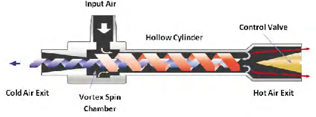
[image:21.595.161.487.320.441.2]“Friendly little demon” is one of the devices can produce, carry out and divide the warm and cold molecule of air suggested by James Clerk Maxwell. He was a great physicist and also suggesting about heat involves the movement molecules (Exair Cooperation, 2013). In addition, the ability of vortex tube is separate air stream into a difference of flow separate air stream into a difference of flow as one, which air inside the inlet is cool while outer is warm without any operation part and it also was significant instrument based on Silverman (1993). The system separation the temperature in vortex tube was not clearly understood, so, this instrument was described using Maxwell Demon in short meaning is dividing heat from cold without using any operation. In figure 1.1 shows the basic construction of Ranque-Hilsch Vortex Tube consist of the control valve, hollow cylinder, exit vortex spin chamber, hot air, cold air exit and input air inlet.
Figure 1.1: The basic construction of Ranque-Hilsch Vortex Tube, (Exair Cooperation, 2013).
3 1.1.2 Vortex Tube Application in Machining
Currently, the application for vortex tubes is used commercially in low-temperature device and applications, for instance, dehumidifying gas samples, to test temperature sensors, to cool food, to chill environment chamber, to cool electric control cabinets, to set solders and to cool parts of the machine (Von, 1950). Vortex tubes are widely used for low equipment cost, safety, and compactness. In the chemical industry, vortex tubes are used for electricity production and snowmaking and etc. Heating and cooling application, gas liquefaction, separation of gas mixture and drying of gases are included in a basic factor for chemical application industry (H. Khazaei et. al, 2012).
4
Figure 1.2: Cooling Molded Fuel Tank (Exair Cooperation, 2002)
5
Figure 1.3: The application of Vortex tube for cooling small parts after brazing, (Exair cooperation, 2002).