EFFECT OF HIGH FREQUENCY INPUT LOCATION FOR CRACK DETECTION IN NONLINEAR VIBRO-ACOUSTIC METHOD
SYARAFANA BINTI MOHAMAD ZAINALABIDIN
EFFECT OF HIGH FREQUENCY INPUT LOCATION FOR CRACK DETECTION IN NONLINEAR VIBRO-ACOUSTIC METHOD
SYARAFANA BINTI MOHAMAD ZAINALABIDIN
This report is submitted
in fulfillment of the requirement for the degree of Bachelor of Mechanical Engineering (Plant & Maintenance)
Faculty of Mechanical Engineering
UNIVERSITI TEKNIKAL MALAYSIA MELAKA
ii
STUDENT’S DECLARATION
I declare that this project report entitled “Effect of High Frequency Input Location For
Crack Detection in Nonlinear Vibro-acoustic Method” is the result of my own work
except as cited in the references
Signature : ...
Name : ...
iii
SUPERVISOR’S APPROVAL
I hereby declare that I have read this project report and in my opinion this report is
sufficient in terms of scope and quality for the award of the degree of Bachelor of
Mechanical Engineering (Plant & Maintenance).
Signature :. ...
Name of Supervisor : ...
iv
DEDICATION
I would like to dedicate this report to my family for being my supporter along the
period of handling this Final Year Project. They have always encourage and advice
me to do this research succesfully. Next, to my supervisor, Dr. Ruztamreen Bin Jenal
that have been always guide me and willingly share his experiences regarding this
v ABSTRACT
Fatigue crack can occur due to the material failure to withstand when load is applied repeatedly. There are a few phases in fatigue life of crack; starting from crack initiation, crack growth and rapid fracture. Basically, from the crack motion, three type of crack modes are formed. Mode I is an opening mode. Mode II is mode of sliding. Mode III is mode of tearing. Even though, crack usually seen in smaller size. But, the growth of it can cause major failure of a structure. Therefore, it is essential to perform inspection in detail. Many methods can be used to detect a crack structure. This involve method of laser vibrometer, eddy current and acoustic emission. In this project, vibro-acoustic method is used for crack detection. Therefore, several step needed to be performed. This includes the process of test specimen preparation, modal analysis test and finally vibro-acoustic wave. Generally, the test specimen preparation involve process of material preparation, tensile test, and dynamic fatigue test. This process essential in way to create the crack on the aluminium plate. Next, the plate will be tested on modal analysis to identify the resonant frequencies of the structure. The resonant frequencies will later be used as the excitation of low frequency in the acoustic test. As for the acoustic signal, 60 kHz will be used in that test. This vibro-acoustic test is chosen to achieve the main objective of the research; to find the effect of high frequency excitation position in crack detection. The output signal formed is then will be transformed in frequency domain using MATLAB software. Finally, the analysed data result in this research proved that the position of high frequency input does not mainly effect the crack detection process.
vi ABSTRAK
vii
ACKNOWLEDGEMENT
All praise to Allah S.W.T; Grateful to God as I had finished my final year project successfully as the time required. Without further ado, I would like to express my thankful to my supervisor Dr. Ruztamreen Bin Jenal for giving me an opportunity to do this final year project with him. He never tired in giving me an advice and guide me every time I encountered problems.
Next, I would like to thank a master student named Tino Hermanto, which has sacrificed his valuable time in helping me in this project research. He have always teach and shared his experience. Also, I would like to thank laboratory assistant, En. Azhar that willingly to do a demonstration regarding on the handling machines. He also have been helped me to scheduled my time to run the experiment smoothly.
viii CONTENT
CHAPTER CONTENT PAGE
STUDENT’S DECLARATION ii
SUPERVISOR’S APPROVAL iii
DEDICATION iv
ABSTRACT v
ABSTRAK vi
ACKNOWLEDGEMENT vii
TABLE OF CONTENT viii
LIST OF TABLES x
LIST OF FIGURES xi
LIST OF ABBREVIATIONS xiii
LIST OF SYMBOLS xiv
CHAPTER 1 INTRODUCTION 1
1.1 Background 1
1.2 Problem Statement 2
1.3 Objective 2
1.4 Scope Of Project 3
CHAPTER 2 LITERATURE REVIEW 4
2.1 Damage in structure 4
2.2 Fatigue crack 5
2.3 Method to detect fatigue crack 6
2.4 Vibro-acoustic method 9
CHAPTER 3 METHODOLOGY 12
3.1 Introduction 12
3.2 Test specimen preparation 14
ix
3.2.2 Crack slot preparation 3.2.3 Tensile test
3.2.4 Dynamic fatigue crack
15 17 17
3.3 Modal analysis test 18
3.4 Vibro-acoustic test 20
CHAPTER 4 DATA AND RESULT 23
4.1 Tensile test 23
4.2 Crack formation 25
4.3 Modal analysis test 26
4.4 Vibro-acoustic test 28
CHAPTER 5 DISCUSSION AND ANALYSIS 32
CHAPTER 6 CONCLUSION AND RECOMMENDATIONS 36
6.1 Conclusion 36
6.2 Recommendations 37
REFERENCES 38
APPENDIX A 42
x
LIST OF TABLES
TABLE TITLE PAGE
3.1 Material properties of an aluminium plate 14
3.2
3.3
Mechanical properties of plate needed to carry out fatigue test
Input parameters needed in modal experiment
17
19
3.4 Points location of PZT transducer at y-axis 21
4.1 Data obtained from tensile test 23
4.2 Several vibration modes and its natural frequencies of cracked
aluminium plate
27
4.3 Value amplitude at graph of FRF of cracked aluminium plate
with low frequency of 67 Hz at point 1 for PZT transducer
29
4.4 Value amplitude at graph of FRF of cracked aluminium plate
with low frequency of 90.5 Hz at point 1 for PZT transducer
30
4.5 Value amplitude at graph of FRF of cracked aluminium plate
with low frequency of 111.5 Hz at point 1 for PZT transducer
31
5.1 Average value of R-index for each vibration mode excitation
on 0 points of high frequency input
xi
LIST OF FIGURES
FIGURE TITLE PAGE
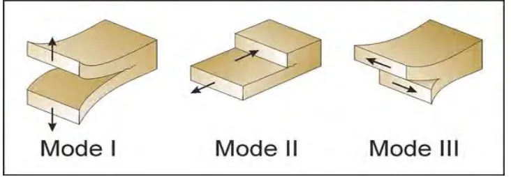
1.1 Fatigue crack modes 1
3.1 Flowchart of methodology 13
3.2 EDM hole drilling machine 15
3.3 EDM wire cut machine 16
3.4 Creation of a slot on an aluminium plate 16
3.5 Gridline of aluminium plate for fatigue crack. 18
3.6 Experimental setup for modal analysis test 19
3.7 Layout of laser stack actuator and PZT transducer on the
aluminium plate
21
3.8 Experimental setup for vibro-acoustic test 22
4.1 Graph of load (kN) and extension (mm). 23
4.2 (a) Picture of front surface of a crack plate 25
4.2 (b) Picture of back surface of a crack plate 25
4.3 Graph of frequency response function (FRF) of crack
aluminium plate
27
4.4 Graph of FRF of cracked aluminium plate with low frequency
of 67 Hz at point 1 for PZT transducer
29
4.5 Graph of FRF of cracked aluminium plate with low frequency
of 90.5 Hz at point 1 for PZT transducer
xii
4.6 Graph of FRF of cracked aluminium plate with low frequency
of 111.5 Hz at point 1 for PZT transducer
31
5.1 Graph of R-index against distance of high frequency input
from crack line at y-axis for first line column (centre of plate) consisting point 1,2,3,4 and 5
34
5.2 Graph of R-index against distance of high frequency input
from crack line at y-axis for second line column (side of plate) consisting point 6,7,8,9 and 10
xiii
LIST OF ABBEREVATIONS
FFT Fast Fourier Transform
CWT Continuous Wavelet Transform
NEWS Nonlinear Elastic Wave Modulation Spectroscopy
TRA Time Reversal Acoustic
MNLW Modulation Nonlinear Lamb Waves
SHM Structural Health Monitoring
TSP Temperature Sensitive Paint
AE Acoustic Emission
VAM Vibro-Acoustic Modulation
PZT Piezoelectric
xiv
LIST OF SYMBOL
𝑓𝑛 = resonant frequency at n-th mode
m = mass of structure
k = stiffness of structure
𝐴0 = ultrasonic amplitude
𝐴1 = first sideband amplitude on the left of the ultrasonic spectrum
𝐴2 = first sideband amplitude on the right of the ultrasonic spectrum
𝐴3 = second sideband amplitude on the left of the ultrasonic spectrum
1
CHAPTER 1
INTRODUCTION
1.1 Background
Fatigue crack is common maintenance problem in industry application such as
steam turbine (Bagaviev and Sheng, 2005) steel bridge (Ichinose, et.al, 2007) and
beams (Eroglu and Tufekci, 2016). Fatigue crack occur due to compressive loads. The
cyclic stress are below the ultimate tensile stress that also can be refer to the strength
of the material. The word “fatigue” is relevant to materials cannot withstand or fails at
the loads applied repeatedly. The fatigue failure or crack occurs in three phases which
includes the initiation of crack, stable crack growth and rapid fracture. There are three
form of crack modes which result from motion of a crack. These modes are opening
[image:16.595.137.503.609.736.2]mode (mode I), sliding mode (mode II) and tearing mode (mode III) which shown in
Figure 1.1. Mode I form in way of crack face move directly apart from each other in
y-direction. Next, mode II refer to a shear stress which are parallel to the plane of the
crack and perpendicular to the crack front. Lastly, if the crack faces act perpendicular
to the crack front, this is known as mode III.
2 1.2 Problem Statement
Vibro-Acoustic method technique is a method of introducing two signal
frequencies in solid structure for crack detection. The two frequencies are high
frequency acoustic wave and low frequency vibration mode. This techniques requires
some parameters that can control the non-linear effect such as excitation location of
high and low frequency and location of measurement point. However, there are still
no detail study that show the effect of high frequency location for crack detection.
Thus, this project is carried out to reveal the effect of high frequency location in
presence of crack.
1.3 Objective
The objectives of this project is seek to:
1. Create a 20 mm crack at the middle of the plate.
2. Determine the effect of high frequency excitation location in crack
3 1.4 Scope of Project
The scopes of this project are:
1. The preparation of specimen which involve some process that includes
cutting an aluminium plate with dimension of 400mm*150mm*2mm ,
drilling hole using EDM wire cutter, line cutting for fatigue crack
initiation and fatigue crack creation.
2. Modal analysis for determination of natural frequency and mode plates
and which require an experimental works, theoretical and calculation.
3. Vibro-acoustic test to evaluate the correlation between parameters
4
CHAPTER 2
LITERATURE REVIEW
2.1 Damage in Structure
In diagnose the structural damage, an approach of signal based pattern is
determined. Each type of damage will form a unique pattern of itself. This studies in
observing the features of frequency-based and time-frequency based. This two features
is obtained from vibration signals that form through fast fourier transform (FFT) and
continuous wavelet transform (CWT). In comparison of CWT and FFT, CWT have
higher resolution of pattern matching because of the preservation of time sensitive and
time. (Qiao et al., 2012).
Discontinuity is one of damage in structure where there is a nonlinear dynamic
structures. The development of discontinuity in cracked bar can be analysed using
nonlinear integral equations and Matlab-Simulink computation (Babitsky and
Hiwarkar, 2016).
Damage in plate structure can be detected using Lamb wave and time reversal
theory. The complicated of Lamb wave propagation are due to dispersion and
multimode feature. Based on this application of time reversal method and propagation
of Lamb wave provide clear image of damage and crack position can be detected (Liu
5 2.2 Fatigue Crack
(Masserey and Fromme, 2013) states “the growth of fatigue crack can be
monitored by using laser interferometer.” It has high accuracy which can detect defects
of medium with long distances. The propagation of high frequency guided ultrasonic
wave can be delivered as a Rayleigh wedge transducer is use for excitation. The growth
of fatigue crack can result in signal changes.
Next, the thickness of a crack can be analysed and studied through the Lamb
wave propagation. Transmission and reflection mode conversion show the interaction
of Lamb waves and crack. This mode of conversions are used to calculate the time
domain and frequency coefficients. As result, as the crack length increase, the
coefficient of transmission will be decreased. Plus, the diffraction of wave is vital in
coefficient of transmission when there is short crack length (Lu et al., 2008).
An aluminium alloy plate in presence of crack can be studied through the
combination of nonlinear elastic wave modulation spectroscopy (NEWS) and time
reversal acoustic (TRA). The purpose of this methods combination are for better
focussing the elastic wave of a crack. PZT transducer were used as the source of
excitation and using equipment such as laser vibrometer, computer and digital
oscilloscope (Gao et al., 2011). There is also a combination of modulation nonlinear
lamb waves (MNLW) and time reversal method in determination of crack on
aluminium alloy plate. Basically, the equipment used is the same as combination
methods of NEWS and TRA. In this duo-technique, there is a presence of harmonics
and sideband which indicate the crack in sample. Meanwhile, no occurrence of
6
There is a study of performance of patch repair between composite and metallic
patches of crack aluminium plates under fatigue loading. Therefore, each type of patch
will be conducted through fatigue test and the growth of crack behaviour will be
analysed. The result show that the fatigue life of aluminium plate when patches with
metal material lower than composite patches; even though metallic patches are weaker
than composite (Saeed and Abid). There is numerical tool to study the propagation of
fatigue crack in aluminium plates when repaired it with composite patch. The tool
involve is finite element analysis and ABAQUS software. Through this method,
parameter such as stress intensity factor can be determined (Maligno et al., 2013).
In studies of turbine blade application, in monitoring condition, parameter of
natural frequencies should be considered. This is essential to determine the conditions
and fatigue life time of blade turbine (Lecheb et al., 2013).
2.3 Method to Detect Fatigue Crack
The development of structural health monitoring (SHM) increasing in demand
of accurate fatigue crack detection. This include the method of elastic wave.The
initiation of fatigue crack of shell structure can be detected through the propagation of
elastic wave. The detection of fatigue crack normally being observed near the hole.
The analysis of this technique is based on frequency domain and time (Stawiarski et
7
A nonlinear acoustics method of damage detection involve classical and
non-classical type. The non-non-classical type consist of propagation of elastic wave and wave
interaction with damage. It has a good sensitivity and also can applied to undamaged
structures, structural damage and structural joints. Example of phenomena of nonlinear
vibration is open and closes of crack under dynamic loading (Pieczonka et al., 2016).
Next, the technique of laser ultrasonic is applied through propagation of
Rayleigh wave in aluminium crack plate inspection. As result, higher number of
components with low frequency will be obtained as the increasing crack depth. So, the
characteristic of fatigue crack is depend on the changes in signal amplitude and centre
frequency (Zhao et al., 2013).
Eddy current is an electromagnetic technique which can also be use in crack
detection. This technique can be applied to weld metal such as steel bridges which can
go through the conductive and paint coatings. Basically, eddy current can be as method
of bridge inspection (Ichinose et al., 2007).
(Caizzone and DiGiampaolo, 2015) states that “In demand of using rapid tools
in tracking structural damage; there is an increasing of using structural health
monitoring (SHM) system. There were three type of category involve in this system.
First, regarding the coupling of some local sensors and structural elements which
include accelerometer, ultrasonic devices and fiber optics. Second, regarding on
bringing instrumentation to demand of measurement site which consists of laser
scanning, X-ray and infrared thermography. Lastly, based on the long distance of
8
interferometry. But, there are improvement of SHM systems that categorized in two
groups regarding the in-situ monitoring techniques. This includes wired and wireless
group. The wired group has great resolution and it is precise. However, there are a few
lack found because of high cost, longer time of installation and complicated. In
comparison, wireless group is a fast and easy installation. There were divided into
active and passive technique. Active technique used battery powered and can be use
in transmission of long distances. But, it is expensive and lifespan is limited that
depend on the battery usage. Meanwhile, in passive technique, use environment as
energy source and also during the wireless communication, powered read out unit is
collected. It can be obtained with low cost and chipless; as example the RFID sensor.
It is used in identification of enlargement crack through wireless technique.”
The fatigue crack in aerospace structure application can be detected by using
an optical technique; temperature sensitive paint (TSP) technology. The technology
involve the temperature sensitivity and there is elimination of pressure sensitive as the
dynamic fatigue increase. Electrodynamic transducer is used in this technology. The
appearance of a crack can be the criterion of failure through this method (Banaszak et
al.).
Another method to detect fatigue crack is through acoustic emission (AE). The
fatigue crack will generate elastic wave by using a piezoelectric transducer that
mounted on the surface. The amplitude of the wave modes differ in crack depth (Kin
LEE et al., 2006). The effect of loading ratio is studied by using AE experiments which
can be seen through the relationship of AE count rates and rates of crack growth
9
of fatigue crack behaviour. The entropy o AE is estimate through time domain. This
way of detection is useful in using the AE signal’s amplitude (Amiri et al., 2015).
Vibrothermography is a transmission of mechanical wave technology that
useful in detecting the hidden crack. It is very quick method; the presence of crack can
be detected less than one second due to the quick propagation of ultrasound wave.
Thus, it does not affect the higher rising of temperature of structure compare to
implusive thermography. This technology is sensitive and can be applied to any metal
cracks such as vertical cracks. However, it is a high cost and not precise in determine
the location of crack depth (Rimare et al., 2012).
In comparison of acoustic emission (AE) and vibration technique on detection
of bearing fault with three condition of different speeds. Result shows that AE signals
will not present as the high frequency of above 50 kHz is involved. The AE signals
has disadvantage where it has limitation on frequency. Thus, AE signals is not precise
in diagnose small fault as the rotary speed slows down compare to the vibration
techniques (Liu et al., 2011).
2.4 Vibro-acoustic Method
Vibroacoustic modulation (VAM) method is common used in crack detection
where it is based on the low frequency vibration and high frequency acoustic wave.
The sideband intensity correlated to the presence of damage. This study observing the
Zhao-Atlas-Marks (ZAM) distribution in analysis of time-frequency. The result shows
that the low frequency vibration modulate the amplitude of the sideband. Plus, the