UNIVERSITI TEKNIKAL MALAYSIA MELAKA
COMPARISON STUDY OF 5 AXIS MACHINE WITH
DIFFERENT CONFIGURATION USING CATIA SOFTWARE
This report submitted in accordance with requirement of the Universiti Teknikal Malaysia Melaka (UTeM) for the Bachelor’s Degree in Manufacturing Engineering
Technology (Process and Technology) with Honours
by
NORAMIN BIN NAZAR SHAH
B071410156
921109-02-5583
ii
DECLARATION
I hereby, declared this report entitled “COMPARISON STUDY OF FIVE AXIS MACHINE WITH DIFFERENT CONFIGURATION USING CATIA SOFTWARE” is the results of my own research except as cited in references.
Signature :………
Name : NORAMIN BIN NAZAR SHAH
iii
APPROVAL
This report is submitted to the Faculty of Engineering Technology of UTeM as a partial fulfillment of the requirements for the degree of Bachelor of Manufacturing Engineering Technology (Process) (Hons.). The member of the supervisory is as follow:
……….
iv
ABSTRAK
Proses pemesinan adalah salah satu proses perindustrian tertua dan merupakan pembuatan industri yang paling banyak digunakan untuk kerja, di mana kira-kira 15% peratus daripada semua komponen mekanikal dibuat oleh proses pemesinan di seluruh dunia. Industri aeroangkasa adalah adalah satu industry yang menggunakan proses pemesinan. Dalam industri ini, kejituan produk yang dihunakan adalah sangat penting berbanding dengan industri lain. Pada masa kini, sesetengah masalah yang dihadapi berdasarkan pemilihan mesin yang sesuai untuk komponen aeroangkasa seperti impeller. Objektif bagi projek ini adalah memahami dua jenis five-axis machine configuration dan mengeluarkan five-axis machining pergerakan mata alat yang sesuai serta membezakan ketepatan komponen yang telah dimesin. Aluminium digunakan sebagai bahan mentah bagi impeller. Five-axis mesin yang telah digunakan adalah HSC 70 linear dan DMU 60 evo manakala strategi permesinan disediakan memalui CATIA V5. Dalam CATIA V5 beberapa strategi telah digunakan diantaranya adalah roughing, multi-axis contouring dan isoparametric. Selepas pemesinan selesai, penilaian ketepatan akan diukur melalui geomagic control x software. Sebelum penilaian ketepatan diukur melalui geomagic control x software impeller yang telah selesai dimesin akan diimbas menggunakan 3D scanning mesin. 3D model yang didapati dri scanning process akan di ukur melalui geomagic control x software akan menyatakan perbezaan antara CAD model dan part yang telah dimesin.
v
ABSTRACT
Machining process is one of the oldest industrial processes and is the most widely used manufacturing industry for work, of which about 15% percent of all mechanical components are made by process machining around the world. Aerospace industry is an industry that uses machining processes. In this industry, the accuracy of the product used is very important compared to other industries. Nowadays, some of the problems encountered are based on the selection of machines suitable for aerospace components such as impeller. The objective of this project is to study two types of five-axis machine configurations and to determine suitable machining tool path in preparing the CAM program in real machining and distinguish the precision of machined. Aluminium is used as a raw material for impeller. The five-axis machine that has been used is HSC 70 linear and DMU 60 evo while CAM program machining strategy is provided through CATIA V5. In CATIA V5 there are several strategies have been used such as roughing, multi-axis contour driven and isoparametric. After machining is complete, evaluation assessment will be measured through the geomagic control X software. Before part measured through the geomagic control X software, the completed machined part will be scanned using the 3D scanner machine. The 3D scanner result in the scanning process will be measured through the geomagic control X software will state the difference between the CAD model and the machined parts.
vi
DEDICATIONS
I dedicate my dissertation work to my family, all my friends and my supervisor, A special feeling of gratitude to my loving parents, Nazar Shah Bin Awang and Norpisah Binti Ahmad whose word of encouragement and always give positive vibes whenever me in depress. My sister Norhanis Binti Nazar Shah that always support and give encouragement to proceed with thesis.
vii
ACKNOWLEDGMENTS
Bismillahirrahmanirrahim
Pease upon you, in the name of ALLAH, The most compassionate. The Most Merciful. Salawat and Salaam to our beloved Prophet, Nabi Muhammad S.A.W with the completion of this thesis report, praise to ALLAH, by Him who given the opportunity and wisdoms.
I would like to thanks to my supervisor Mr Muhammad Syafik Bin Jumali for his full support, expert guidance, understanding and encouragement throughout my study and research. Without his incredible patience and timely wisdom and counsel, my thesis work would have been a frustrating and overwhelming pursuit.
Thanks also go to my fellow friends and all assistance engineers at the Faculty of Engineering Technology of University Technical Malacca. Special thanks go to them who helped me throughout this academic exploration.
viii
TABLE OF CONTENTS
DECLARATION ii
APPROVAL iii
ABSTRAK iv
ABSTRACT v
DEDICATIONS vi
ACKNOWLEDGMENTS vii
TABLE OF CONTENTS viii
LIST OF TABLES xi
LIST OF FIGURES xii
LIST OF ABBREVIATIONS, SYMBOLS AND NOMENCLATURES xv
CHAPTER 1 1
INTRODUCTION 1
1.1 Project’s Background 1
1.2 Problem Statement 3
1.3 Objectives 4
1.4 Scope 5
CHAPTER 2 6
LITERATURE REVIEW 6
2.1 Machine Features 6
2.1.1 HSC 70 Linear 6
2.1.2 DMU 60 evo 7
2.2 Five-axis Machining 9
ix
2.4 Five-axis Flank Milling 12
2.5 Accuracy Five Axis Machining 15
2.6 Impeller Blade 16
2.7 Aluminium 17
CHAPTER 3 22
METHODOLOGY 22
3.1 Project Planning 23
3.2 Phase I 25
3.2.1 Problem Simulation 25
3.2.2 Literature Review to Understand Better Topic 25 3.2.3 Searching/Sketching Suitable CAD Model and Verification 26
3.2.4 Assembly of CAD Product 27
3.3 Phase II 29
3.3.1 Material and Suitable Cutting Tool 29
3.3.2 Preparation for CAM Strategy 31
3.3.2.1 Roughing 34
3.3.2.2 Isoparametric 36
3.3.2.3 Multi-axis Contour Driven 39
3.3.3 Preparation for Process strategy 49
3.3.4 Post Processing 51
3.3.5 Physical Machining 53
x
CHAPTER 4 60
RESULT AND DISCUSSION 60
4.1 Result 60
4.2 Comparison of Impeller 63
4.3 Problem of Accuracy on Impeller 66
4.4 Machined Part Problem 67
CHAPTER 5 70
CONCLUSION AND FUTURE WORK 70
5.1 Conclusion 70
5.2 Future Work 71
xi
LIST OF TABLES
Table 3.1: Detail Dimension of Selected Cutting Tool ... 30
Table 3.2: Setting of Roughing Process ... 35
Table 3.3: Setting of Isoparametric for Blades ... 38
Table 3.4: Setting of Multi-axis Contour Driven for gap between Blades ... 42
Table 3.5: List of Lead and Tilt Angle based on labelling number space between blades... 43
Table 3.6: Setting of Multi-axis Contour Driven for inside Blades ... 45
Table 3.7: Setting of Multi-axis Contour Driven for Outside Blades ... 47
Table 3.8: List of Lead and Tilt Angle based on labelling number Inside Blades. .... 48
Table 3.9: List of Lead and Tilt Angle based on labelling number Outside Blades .. 49
Table 4.1: Result for HSC 70 linear Machine Part ... 65
xii
LIST OF FIGURES
xiii
Figure 3.3: Cad model with stock and axis system. ... 27
Figure 3.4: Plane system ... 27
Figure 3.5: List of Cutting Tool ... 30
Figure 3.6: Setting of Part Operation ... 31
Figure 3.7: Flow Chart CAM Process ... 33
Figure 3.8: First Roughing Simulation ... 35
Figure 3.9: Second Roughing Simulation ... 36
Figure 3.10: Isoparametric simulation ... 36
Figure 3.11: Labelling number on Space between Blades ... 43
Figure 3.12: Labelling number on Blade ... 48
Figure 3.13: Machining Feedrate and Spindle speed ... 50
Figure 3.14: Retract Feedrate and Approach Feedrate... 51
Figure 3.15: NC code save into .H file... 52
Figure 3.16: APT save into .MPF file ... 52
Figure 3.17: Simulation for HSC 70 linear ... 53
Figure 3.18: Simulation for DMU 60 evo linear ... 54
Figure 3.19: Function 3D Scanner ... 55
Figure 3.20: Flow Chart of 3D Scanner ... 56
Figure 3.21: 3D Scanner Model ... 56
Figure 3.22: Before Applying Spray Substance ... 57
xiv
Figure 3.24: CAD Model ... 58
Figure 3.25: HSC 70 Linear Best Fit Alignment ... 59
Figure 3.26: DMU 60 evo Best Fit Alignment ... 59
Figure 4.1: Result of Machined part by DMU 60 evo ... 61
Figure 4.2 Result of Machined Part by HSC 70 linear ... 61
Figure 4.3: Result of 3D scanner for DMU 60 evo ... 62
Figure 4.4: result of 3D Scanner for HSC 70 linear ... 62
Figure 4.5: 3D Compared for HSC 70 linear Machined Part ... 63
Figure 4.6: 3D Compared for DMU 60 evo Machined Part ... 64
Figure 4.7: DMU 60 evo scanning problem ... 66
Figure 4.8: HSC 70 linear scanning problem ... 67
Figure 4.9: Machined Part HSC 70 Linear Problem ... 67
Figure 4.10: Machined Part DMU 60 evo problem ... 68
xv
LIST OF ABBREVIATIONS, SYMBOLS AND
NOMENCLATURES
CAM = Computer Aided Manufacturing CAD = Computer Aided Design
CATIA = Computer Aided three-dimensional Interactive Application
NC = Numerical Code
CNC = Computer Numerical Code STL = Standard Triangle Language
UTeM = Universiti Teknikal Mlaysia Melaka Ksi = Kilopound per square inch
1
CHAPTER 1
INTRODUCTION
This chapter will explain the overview of the study and the purpose of this study. The chapter includes the background of the study, problem statement, objectives that is expected to be achieved and the scope of the study that is going to be conducted
1.1 Project’s Background
Machining process is one of the oldest industrial processes and it is the most industrial manufacture of work piece used, where is estimated that is 15% percent of all mechanical components are made by machining process all around the world. (Calamez et al., 2008). Today, CADCAM system still remain an important role among the tools for digital manufacturing and digital factory, and take a major part in interaction activities between human and computers in manufacturing industry. This will be strengthened further due to evolvement towards a high level of flexibility in the manufacturing industry. (Li et al., 2015). CADCAM software have addition function such as collision-avoidance capabilities and advanced simulation for five-axis program. CADCAM software is designed to cut the complex part used in many areas such as die-mold, aerospace and medical machining applications. (Patrick Waurzyniak, 2007).
2 influences the performances of machining operation. It is because a good quality turned surface significantly improves the quality. (Patel et al., 2012). With the ever increasing demands for higher and higher accuracy on modern CNC equipment, the manufacturing processes for machining and assembling the structural components are an increasingly important factor in establishing a geometrically correct machine tool especially flatness, parallelism and straightness of interfacing surfaces determine whether the machine tool’s basic accuracy. (Hansel et al., 2014)
Recently, five axis and multi-axis machining methods have been looked by CAM software suppliers to solidify their offerings for users trying to stay competitive by using more complex manufacturing techniques. Large 5-axis multi spindle gantry milling machine, because of its multi spindle can process simultaneously, making a substantial increase in production efficiency, is an important role of the main CNC machining equipment for the efficient production of high value large aircraft structure part. (Qin Xiaopin et al, 2016). To machine the parts with accurate dimensions and shapes and low machining costs, it is necessary to construct 3D models of the finished parts in the geometric simulation and in-process work piece models of the parts in the physical simulation of their five axis milling.
3 One of the leading solutions for product success is CATIA V5. CATIA V5 is a software that addresses all organization related with manufacturing field which from minor independent manufacturer until their supply chains. CATIA – which stands for Computer Aided Three-dimensional Interactive Application is the most powerful and widely used CAD software of its kind in the world. CATIA is widely used for designing purposes in aerospace sector and few other segment of industries as well.
Surface roughness is a main parameter in Computer Numerical Control (CNC) technology meanwhile getting the optimization parameter for surface roughness is a hard solving issue because of the interaction between the parameters. Surface roughness of the contacting surfaces influences the frictional properties of those surfaces during the forming processes. Furthermore, it is well known that the final geometry of surface roughness is influenced by various machining conditions such as spindle speed, feed rate and depth of cut (Kumar et al., 2012). Surface roughness parameter also plays an important role in manufacturing industries as it can influence friction, wear and lubricants of contacting bodies.
1.2 Problem Statement
5-axis machining has become much more prevalent in today’s manufacturing market place, and although the overall knowledge base of machinists and operators has grown by leaps and bounds over the past several years, there is still a great deal of misunderstanding and mystery surrounding accuracy both as it applies to the workpiece itself, and also how the overall positioning of the rotary axis of the machine might be effected.
4 of the workpiece, the accuracy of the overall process will inherently improve and the accuracy of the individual part should theoretically be as close as the machine tool is capable of positioning but understanding what factors are in play that might affect the overall accuracy of a particular process is at the heart of creating an accurate workpiece.
Five-axis CNC machining is suitable to machine complex part. Five-axis CNC machining provides a high quality of product or part and given good positional accuracy. Simulation done in software such as CATIA V5 helps in determining defect occur before physical machining. This step helps in preventing wasted material. HSC 70 and DMU 60 evo are Five-axis CNC milling machine commonly used for a machining process. Both of the machine have same post processor but using a different controller and configuration. It’s give difficulty to make a decision which one of the machine have a better accuracy to create impeller. Accuracy of machine will be analysed by part that have been machined in term of dimensional accuracy using coordinate measuring machine.
1.3 Objectives
Based on the problems that have been stated beforehand, this study aims to:
i. To study DMU 60 evo and HSC 70 linear machine configuration
ii. To determine suitable machining tool path in preparing the CAM program for Impeller using CATIA V5 software in real machining
5
1.4 Scope
6
CHAPTER 2
LITERATURE REVIEW
This chapter explains about all findings obtained from many literature reviews, which may come from the internet, journals, article and books about the topic related to this study. This section includes findings about the overview of machine features, Five-axis machining, Ball End Milling Process, Five-Five-axis Flank Milling and accuracy five-axis machining.
2.1 Machine Features
Nowadays, there are many five axis milling machine is being used in aerospace manufacturing. In this project we will use machine from company DMG MORI which is HSC 70 Linear and DMU 60 evo.
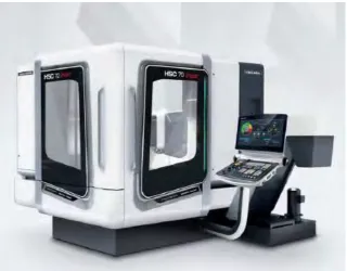
2.1.1 HSC 70 Linear
7 and the rotary A-axis behind the milling spindle. Spindle speed of up to 18,000 rpm. Powerful milling performance, with an optional 40,000 rpm. EGROline control panel with a 21.5 multi-touch-screen on a Siemens control. In addition to highly dynamic linear drives and new high-performance spindles with shaft, flange and jacket cooling, the thermosymmetrical design and special cooling measures ensure maximum precision and productivity. (Centers, n.d.)
Figure 2.1 : HSC 70 Linear five axis Milling Machine (adapted from Centers, n.d.)
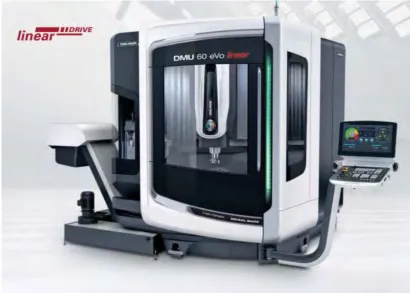
2.1.2 DMU 60 evo
8 or in serial production runs. Whether for machine construction, tool and mold making, medical technology, automotive, or aerospace projects – when precision and flexibility are as important as time and cost savings, the DMU evo Series delivers efficient technology for unmatched results.In addition to offering optimal accessibility and impressive dynamics, the eVo Series delivers exceptional performance and power options with 10,000 rpm. and 18,000 rpm. The machine's construction features minimal axes projection for unparalleled stability and rigidity over the entire travel area that delivers impressive long-term precision. Positioning of the Y-slide and a round cabin design offer easy access to the work area. Even with integrated handling systems, front access to the work area is retained. Additionally, the machine’s shallow reach-in depth and optimal loading height provide favorable ergonomics. A left-side positioned tool magazine and chain carrier layout offer a similar setup area for all magazine sizes.(Centers, n.d.)
9
2.2 Five-axis Machining
The term of “five-axis” are refer to the number of the direction which the cutting tool can move. On a five-axis machining center, the cutting tool will moves across the X, Y and Z linear axes as well as rotates on the A and B axes approach the work piece form any direction. According to, five-axis machining technologies has been used widely in the production of complex parts in aerospace, automotive parts and biomedical industries. With five-axis machining, parts can be machined in a single setup which will reduces recycle times. The main focus of using five-axis machining in industry is to reduce times, dimensional and surface error on its nature. However, these desired points cannot be achieved satisfactorily without modelling of five-axis milling mechanics. Figure 2.3 below shows simulated five-axis impeller machining and tool path.
Figure 2.3: Simulated of impeller in five-axis machining (adapted Lazoglu et al., 2011)