This is a repository copy of An experimental study of the putative mechanism of a
synthetic autonomous rotary DNA nanomotor.
White Rose Research Online URL for this paper:
http://eprints.whiterose.ac.uk/114023/
Version: Published Version
Article:
Dunn, Katherine Elizabeth orcid.org/0000-0002-5068-4354, Leake, Mark Christian
orcid.org/0000-0002-1715-1249, Wollman, Adam orcid.org/0000-0002-5501-8131 et al. (3
more authors) (2017) An experimental study of the putative mechanism of a synthetic
autonomous rotary DNA nanomotor. Royal Society Open Science. 160767. ISSN
2054-5703
https://doi.org/10.1098/rsos.160767
[email protected] https://eprints.whiterose.ac.uk/
Reuse
This article is distributed under the terms of the Creative Commons Attribution (CC BY) licence. This licence allows you to distribute, remix, tweak, and build upon the work, even commercially, as long as you credit the authors for the original work. More information and the full terms of the licence here:
https://creativecommons.org/licenses/ Takedown
If you consider content in White Rose Research Online to be in breach of UK law, please notify us by
Supplementary Information: An experimental
study of the putative mechanism of a synthetic
autonomous rotary DNA nanomotor
K.E. Dunn
∗1, M.C. Leake
2, A.J.M. Wollman
2, M.A. Trefzer
1,
S. Johnson
1, and A.M. Tyrrell
11
Department of Electronics, University of York, Heslington, York,
YO10 5DD, UK
2
Biological Physical Sciences Institute, Departments of Physics
and Biology, University of York, Heslington, York, YO10 5DD, UK
1
Sequences
The sequences of all DNA strands used in this work are given in the following
tables. All sequences are written 5’ to 3’. So-called ‘pseudosequences’ were used
to design the molecules and represent their structure in terms of domains. For
example, the ‘pseudosequence’ (CSr,T8,BDA,X1r) denotes a sequence
compris-ing, in order, the reverse complement of CS, 8 thymine bases, the domain called
‘BDA’, and the reverse complement of X1. For the simpler experiments, the
symbol * is used to denote the reverse complement of a domain or strand, such
as CS*. The sequences of CSr and CS* are identical. All strands were acquired
∗To whom correspondence should be addressed. E-mail: [email protected]
with standard desalting purification, with the exception of the thiol-modified
strand CS, for which HPLC purification was selected. All oligonucleotides were
supplied by Integrated DNA Technologies.
1.1
Sequential strand displacement in a linear construct
The strands used to study sequential strand displacement in a linear construct
are below. Note that the strand CS was used throughout this work. It is listed
here only in this table.
Name Sequence
CS ACA CGC ATA CAC CCA T-(thiol)
X AAA CGC ACT ACG GCT CAG ATG TCC ACG AAC GCC ACC AAG G
X* CCT TGG TGG CGT TCG TGG ACA TCT GAG CCG TAG TGC GTT T
Block-1 CTG AGC CGT AG
Block-2 TTC GTG GAC AT
Block-3 ATG GGT GTA TGC GTG TCC TTG GTG GCG
Table 1: Sequences of DNA oligonucleotides used to examine sequential strand displacement in an immobilized linear construct.
1.2
Strand displacement in a geometrically constrained
structure (‘Triangle’ experiment)
Table 2 provides the sequences used to assemble the triangle and trigger strand
displacement reaction within it. Lower case letters represent domain names and
the sequence T3is inserted in places to ensure flexibility at corners. The strand
name T is not to be confused with the representation of a single thymine.
Name Pseudosequence Base sequence
T CS*, a, T3, b, T3, c,
T3, d, t
ATG GGT GTA TGC GTG TTG TTG GTG TGT TTC TCC TCC TCC TTT CTG CCT GCC TTT TGC CGC CGC CGA TCA GCA T
ac-staple a*, T3, c* CAC ACC AAC ATT TAG GCA GGC AG
bd-staple b*, T3, d* GGA GGA GGA GTT TCG GCG GCG GC
Control-a a−* ACA CCA AC
Control-b b−* GAG GAG GA
Control-c c−* GGC AGG CA
Control-d d−* GGC GGC GG
T* (CS*, a, T3, b, T3,
c, T3, d, t)*
ATG CTG ATC GGC GGC GGC AAA AGG CAG GCA GAA AGG AGG AGG AGA AAC ACA CCA ACA ACA CGC ATA CAC CCA T
RC(ac-staple) (a*, T3, c*)* CTG CCT GCC TAA ATG TTG GTG TG
RC(bd-staple) (b*, T3, d*)* GCC GCC GCC GAA ACT CCT CCT CC
Table 2: Sequences of DNA oligonucleotides used to construct the nano-triangles, confirm whether they had assembled correctly, and induce strand displacement. The abbreviation ‘t’ denotes the toehold. The − subscript in the pseudosequences for the control strands indicates that the first and last nucleotide of these domains was omitted.
1.3
The rotary motor
Three tables are provided, listing the pseudosequence of each strand (Table 3),
the sequence of each domain referred to in the pseudosequences (Table 4) and
the final sequence of each strand (Table 5). The definition of the domains in the
pseudosequences is given in Fig. S1, while Fig. S2 shows the strand exchange
mechanism for the first quarter turn.
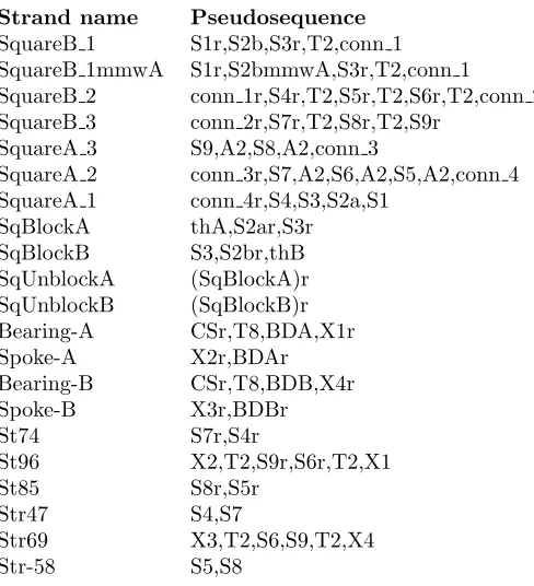
Strand name Pseudosequence SquareB 1 S1r,S2b,S3r,T2,conn 1 SquareB 1mmwA S1r,S2bmmwA,S3r,T2,conn 1 SquareB 2 conn 1r,S4r,T2,S5r,T2,S6r,T2,conn 2 SquareB 3 conn 2r,S7r,T2,S8r,T2,S9r
SquareA 3 S9,A2,S8,A2,conn 3
SquareA 2 conn 3r,S7,A2,S6,A2,S5,A2,conn 4 SquareA 1 conn 4r,S4,S3,S2a,S1
SqBlockA thA,S2ar,S3r
SqBlockB S3,S2br,thB
SqUnblockA (SqBlockA)r
SqUnblockB (SqBlockB)r
Bearing-A CSr,T8,BDA,X1r
Spoke-A X2r,BDAr
Bearing-B CSr,T8,BDB,X4r
Spoke-B X3r,BDBr
St74 S7r,S4r
St96 X2,T2,S9r,S6r,T2,X1
St85 S8r,S5r
Str47 S4,S7
Str69 X3,T2,S6,S9,T2,X4
[image:5.612.141.385.252.520.2]Str-58 S5,S8
Table 3: Pseudosequences of strands used to design the rotary motor.
Domain name Sequence S1r CCA CGA TGC C
S2b ACC TCA TCC C
S2bmmwA GTT CAA TCC C
S3r GAA TGC ATG A
S4r CAT GAC GTT A
S5r CCA TTG GCT G
S6r ATG TGA CTG G
S7r GAA TCT CAC T
S8r GTT CGG CTC C
S9r AAG TCA GTA T
S1 GGC ATC GTG G
S2a ACC GAG TGG T
S3 TCA TGC ATT C
S4 TAA CGT CAT G
S5 CAG CCA ATG G
S6 CCA GTC ACA T
S7 AGT GAG ATT C
S8 GGA GCC GAA C
S9 ATA CTG ACT T
thA ACC ACC
thB GAG AGA
BDA TCT ACC TAT T
BDB CCA GTT GCT C
X1 CTA TAA CCG A
X2 ATC AAA GGG T
X3 AGC GAT TCA C
X4 ATT ACA AAA T
thAr GGT GGT
thBr TCT CTC
BDAr AAT AGG TAG A
BDBr GAG CAA CTG G
X1r TCG GTT ATA G
X2r ACC CTT TGA T
X3r GTG AAT CGC T
X4r ATT TTG TAA T
conn 1 GAG AAG AGA AGA GAA GAG AA
conn 2 GCA AAA CGA AAA GCA AAA CG
conn 3 GAA GAA GAA GAA GAA GAA GA
conn 4 GAA AGA AAG AAA GAA AGA AA
conn 1r TTC TCT TCT CTT CTC TTC TC
conn 2r CGT TTT GCT TTT CGT TTT GC
conn 3r TCT TCT TCT TCT TCT TCT TC
[image:6.612.140.357.150.653.2]conn 4r TTT CTT TCT TTC TTT CTT TC
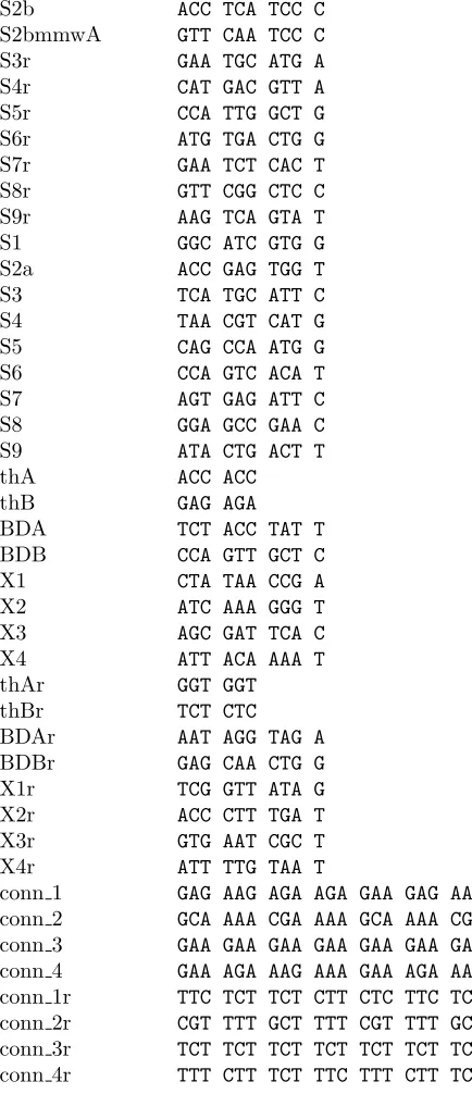
Table 4: Sequences of the individual domains of the oligonucleotides from which the rotary motor was assembled. Names refer to the pseudosequences defined previously.
Strand name Sequence
SquareB 1 CCA CGA TGC CAC CTC ATC CCG AAT GCA TGA TTG AGA AGA GAA GAG AAG AGA A
SquareB 1 mmwA CCA CGA TGC CGT TCA ATC CCG AAT GCA TGA TTG AGA AGA GAA GAG AAG AGA A
SquareB 2 TTC TCT TCT CTT CTC TTC TCC ATG ACG TTA TTC CAT TGG CTG TTA TGT GAC TGG TTG CAA AAC GAA AAG CAA AAC G
SquareB 3 CGT TTT GCT TTT CGT TTT GCG AAT CTC ACT TTG TTC GGC TCC TTA AGT CAG TAT
SquareA 3 ATA CTG ACT TAA GGA GCC GAA CAA GAA GAA GAA GAA GAA GAA GA
SquareA 2 TCT TCT TCT TCT TCT TCT TCA GTG AGA TTC AAC CAG TCA CAT AAC AGC CAA TGG AAG AAA GAA AGA AAG AAA GAA A
SquareA 1 TTT CTT TCT TTC TTT CTT TCT AAC GTC ATG TCA TGC ATT CAC CGA GTG GTG GCA TCG TGG
SqBlockA ACC ACC ACC ACT CGG TGA ATG CAT GA
SqBlockB TCA TGC ATT CGG GAT GAG GTG AGA GA
SqUnblockA TCA TGC ATT CAC CGA GTG GTG GTG GT
SqBlockB mmwA TCA TGC ATT CGG GAT TGA ACG AGA GA
SqUnblockB mmwA TCT CTC GTT CAA TCC CGA ATG CAT GA
SqUnblockB TCT CTC ACC TCA TCC CGA ATG CAT GA
Bearing-A ATG GGT GTA TGC GTG TTT TTT TTT TCT ACC TAT TTC GGT TAT AG
Spoke-A ACC CTT TGA TAA TAG GTA GA
Bearing-B ATG GGT GTA TGC GTG TTT TTT TTT CCA GTT GCT CAT TTT GTA AT
Spoke-B GTG AAT CGC TGA GCA ACT GG
St74 GAA TCT CAC TCA TGA CGT TA
St96 ATC AAA GGG TTT AAG TCA GTA TAT GTG ACT GGT TCT ATA ACC GA
St85 GTT CGG CTC CCC ATT GGC TG
Str47 TAA CGT CAT GAG TGA GAT TC
Str69 AGC GAT TCA CTT CCA GTC ACA TAT ACT GAC TTT TAT
TAC AAA AT
[image:7.612.139.487.136.637.2]Str58 CAG CCA ATG GGG AGC CGA AC
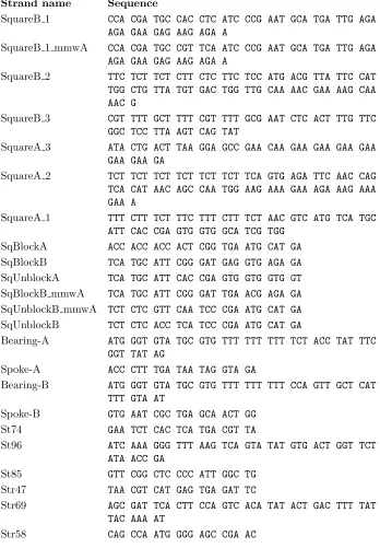
Table 5: Sequences of the DNA oligonucleotides used to assemble and unblock the rotary motor.
Fig. S1: A detailed schematic diagram of the motor components, showing the different domains. Strand names are given in italics, domain names are given in Roman type. All staple domains except X1-4 are left unlabelled. The double-stranded spokes formed by domains whose names begin with ‘conn’ play no part in the operation of the motor. For this prototype, the tapes were constructed using multiple oligos joined together, and the connection domains are irrelevant to the rotation mechanism.
Fig. S2: Sketches showing the mechanism of strand exchange for the first quarter of a turn.
1.3.1 Analysis of motor domains using NUPACK
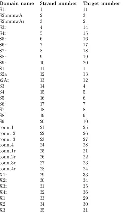
For data entry into NUPACK (see citation in main paper), each of the relevant
domains was given a number, as listed in Table 6. Results are shown in Table
7.
Domain name Strand number Target number
S1r 1 11
S2bmmwA 2 3
S2bmmwAr 3 2
S3r 4 14
S4r 5 15
S5r 6 16
S6r 7 17
S7r 8 18
S8r 9 19
S9r 10 20
S1 11 1
S2a 12 13
s2Ar 13 12
S3 14 4
S4 15 5
S5 16 6
S6 17 7
S7 18 8
S8 19 9
S9 20 10
conn 1 21 25
conn 2 22 26
conn 3 23 27
conn 4 24 28
conn 1r 25 21
conn 2r 26 22
conn 3r 27 23
conn 4r 28 24
X1r 29 33
X2r 30 34
X3r 31 35
X4r 32 36
X1 33 29
X2 34 30
[image:10.612.141.394.211.645.2]X3 35 31
Table 6: Numbering the domains for data entry into NUPACK.
Complex Description Correct target? Yield (%) ∆G(kJ/mol) ∆G/(kBT)
22-26 Dimer Yes 100.0 -142.9 -58.7
21-25 Dimer Yes 100.0 -129.5 -53.2
23-27 Dimer Yes 100.0 -128.7 -52.8
24-28 Dimer Yes 100.0 -122.2 -50.2
9-19 Dimer Yes 99.9 -77.1 -31.6
1-11 Dimer Yes 99.8 -78.4 -32.2
31-35 Dimer Yes 99.5 -72.5 -29.8
7-17 Dimer Yes 99.5 -69.4 -28.5
6-16 Dimer Yes 99.3 -73.1 -30.0
5-15 Dimer Yes 99.2 -68.5 -28.1
4-14 Dimer Yes 99.2 -68.1 -27.9
2-3 Dimer Yes 99.1 -66.7 -27.4
30-34 Dimer Yes 98.8 -67.9 -27.9
29-33 Dimer Yes 98.6 -64.5 -26.5
8-18 Dimer Yes 97.9 -64.4 -26.4
12-13 Dimer Yes 97.4 -78.4 -32.2
10-20 Dimer Yes 97.3 -61.3 -25.1
32-36 Dimer Yes 81.7 -55.0 -22.6
32 Monomer Not hybridized 18.3 -1.6 -0.6
36 Monomer Not hybridized 18.3 -2.2 -0.9
20 Monomer Not hybridized 2.7 -0.2 -0.1
10 Monomer Not hybridized 2.7 -0.2 -0.1
12 Monomer Not hybridized 2.6 -9.1 -3.7
13 Monomer Not hybridized 2.6 -8.1 -3.3
8 Monomer Not hybridized 2.1 -1.2 -0.5
18 Monomer Not hybridized 2.1 -0.9 -0.4
29 Monomer Not hybridized 1.4 -0.1 0.0
33 Monomer Not hybridized 1.4 -0.1 -0.1
34 Monomer Not hybridized 1.2 -1.1 -0.5
[image:11.612.142.531.122.499.2]30 Monomer Not hybridized 1.2 -1.9 -0.8
Table 7: Results of NUPACK computation, showing the equilibrium configura-tion for the strands listed in Table 6 (1-36). The maximum complex size was 2 strands, the temperature was 20◦C, the concentration of all strands was 1µM and 1 M sodium was used. All structures having a concentration greater than 0.01µM are listed in this table. The yield is defined as a percentage, represent-ing the concentration of the product divided by the reference concentration of 1µM. All domains hybridize strongly with their intended targets.
2
Detailed experimental procedures: QCM-D
experiments
2.1
General notes
• Apparatus used: Q-sense E4 machine, Biolin Scientific.
• Sensors: Gold-coated AT-cut quartz sensors (fundamental frequency 4.95MHz
+/- 50kHz), Biolin Scientific, ref. no. QSX 301.
• Sensor cleaning: Before use, sensors were cleaned as follows, in accordance
with the procedure described previously (see reference in manuscript). 10
minutes in UV-ozone cleaner, 10 minutes sonication in 2% Hellmanex III,
10 minutes sonication in ultrapure water (twice), drying with N2 gas, 30
minutes in UV-ozone cleaner, 30 minutes soak in 100% ethanol, drying
with N2 gas.
The apparatus contains four flow modules, which means that up to four
experiments can be run in parallel. Liquids were driven through the QCM-D
apparatus using a peristaltic pump. The depth in solution to which an acoustic
wave reaches is dependent on the frequency of the wave, and higher overtones
probe only the region nearest to the surface. Data is shown for the thirteenth
overtone, which is the highest frequency that can be observed with this system.
The experiment was performed at 16◦C, with a pump flow rate of 20µL/min.
After sensors had been installed in the flow modules, the system was flushed
with ultrapure water, followed by the experimental buffer, which was 1M NaCl
in 1xTE (Tris-EDTA, pH8). Samples were then supplied and as the molecules
bound to the surface, the frequency of the crystal decreased. The sections below
provide step-by-step details of the workflow for each experiment performed.
2.1.1 Sequential strand displacement in a linear construct
The complex comprising CS and Block-3 was formed by mixing equimolar
quan-tities of the two strands in a buffer of 1×TE with 1M NaCl and incubating
the sample at room temperature for a period sufficient for hybridization. The
CS/Block-3 complex was at a concentration of 300 nM, and all other strands
were supplied at 750 nM. Between steps the sensor was washed with buffer for
4-5 minutes; throughout the experiment the buffer used was 1×TE with 1M
NaCl. In the final step strand X* was applied, where X* is the reverse
comple-ment of strand X.
2.2
Strand displacement in a geometrically constrained
structure (‘Triangle’ experiment)
Samples were prepared as follows. In all cases, the buffer was 1×TE with 1M
NaCl. The final concentration is given.
• CS: 300nM
• T: 750nM
• S: 750nM ac-staple, 750nM bd-staple (note that the letter S is used later
to denote something else)
• Control a: 750nM
• Control b: 750nM
• Control c: 750nM
• Control d: 750nM
• Additional controls (mixture): 750nM RC(ac-staple), 750nm RC(bd-staple)
• T*: 750nM
• F(T): 750nM T, 7.5µM ac-staple, 7.5µM bd-staple, anneal in thermal
cycler from 95◦C to 20◦C at 1◦C/min.
• F(T*) 750nM T*, 7.5µM RC(ac-staple), 7.5µM RC(bd-staple), anneal in
thermal cycler from 95◦C to 20◦C at 1◦C/min.
The QCM-D experiment was performed as described above. Samples were
applied to the sensors as follows, where the approximate duration of each step
of the experiment is shown in brackets, in minutes.
Fig. 3(b) top panel, Fig. 3(c) left panel: Buffer (17), CS (35), buffer (5),
T (18), buffer (5), S (26), buffer (7), control a (10), buffer (7), control b (10),
buffer (6), control c (10), buffer (8), control d(8), buffer (25), additional control
(10), buffer (5), T* (until sample ran out)
Fig. 3(b) middle panel, Fig. 3(c) middle panel: Buffer (17), CS (35), buffer
(28), F(T) (26), buffer (7), control a (10), buffer (7), control b (10), buffer (6),
control c (10), buffer (8), control d (8), buffer (7), additional control (18), buffer
(15), T*(until sample ran out)
Fig. 3(b) bottom panel, Fig. 3(c) right panel: Buffer (17), CS (35), buffer
(28), F(T) (26), buffer (7), control a (10), buffer (7), control b (10), buffer (6),
control c (10), buffer (8), control d (8), buffer (40), F(T*) (until sample ran
out)
2.2.1 The rotary motor
Step 1: preparation of squares
The components were made as follows, by mixing the named strands in a
buffer of 1×TE with 1M NaCl, and annealing from 95◦C to 20◦C in a
thermo-cycler with a cooling rate of 1◦C/min. The final concentration of each strand is
given in brackets.
Definitions: =square; B=blocked; F=folded; UF=unfolded; S=functionalized
for surface immobilization.
BFA = SquareA 1 (1µM), SquareA 2 (1µM), SquareA 3 (1µM), St96 (1µM),
Spoke-A (1µM), St74 (5µM), St85 (5µM), SqBlockA (5µM)
FA = SquareA 1 (1µM), SquareA 2 (1µM), SquareA 3 (1µM), St96 (1µM),
Spoke-A (1µM), St74 (5µM), St85 (5µM)
BFB = SquareB 1mmwA (1µM), SquareB 2 (1µM), SquareB 3 (1µM),
Str69 (1µM), Spoke-B (1µM), Str47 (5µM), Str58 (5µM), SqBlockBmmwA
(5µM)
FB = SquareB 1mmwA (1µM), SquareB 2 (1µM), SquareB 3 (1µM), Str69
(1µM), Spoke-B (1µM), Str47 (5µM), Str58 (5µM)
UFB = SquareB 1mmwA (1µM), SquareB 2 (1µM), SquareB 3 (1µM)
Step 2: preparation of surface attachment units
The following samples were prepared in the same buffer, and incubated at
room temperature for approximately 30 minutes to allow the strands to
hy-bridize.
T1 =1:1 mixture of CS and Bearing-A, final concentration 25µM
T2 =1:1 mixture of CS and Bearing-B, final concentration 25µM
Step 3: combination of squares and surface attachment units
Samples from step 1 were combined with samples from step 2 to form squares
that could be immobilized on the gold surface, as follows. Mixtures were
incu-bated at room temperature for a period sufficient to allow hybridization.
SBFA = 1:25 (by volume), T1 :BFA.
SFA = 1:25 (by volume), T1 :FA. (Like SBFA, but without blocking
strand.)
SBFB = 1:25 (by volume), T2 :BFB.
Note that 8 consecutive thymine nucleotides are left unpaired in the surface
attachment unit, to provide a flexible linker region that enables rotation to
occur. If the linker were rigid, no rotation would be possible.
Step 4: mixing with MCH If the density of motors on the surface is
too high, operation is impossible because they interact and/or collide. To avoid
this, the samples from Step 3 were mixed with MCH (6-mercapto-1-hexanol),
a thiolated molecule that will be immobilized at the same time as the motors.
The original concentration of MCH was 1mM. In all cases, the final buffer was
1×TE with 1M NaCl.
Sample 1 = 1:1 (by volume), SFA : MCH.
Sample 2 = 2:2:1 (by volume), SBFA : SBFB : MCH.
Sample 3 = As sample 1.
Sample 4 = 1:1 (by volume), SBFA : MCH.
Sufficient time was allowed for the two halves of the motor to hybridize in
sample 2.
Step 5: QCM-D experiments Freshly cleaned sensors were installed in
the flow modules, which were then flushed with ultrapure water, followed by the
experimental buffer, which was 1M NaCl/TE. The samples listed above were
supplied, where sample X was used for flow module X. When a plateau was
reached, the sensors were rinsed with buffer. The following solutions were then
applied to the sensors:
Sensor 1: UFB from Step 1, followed by buffer
Sensor 2 (consecutively): UnblockA (1µM), buffer (short rinse step),
Un-blockB mmwA
Sensor 3: FB from Step 1, followed by buffer
Sensor 4 (consecutively): UnblockA (1µM), buffer (short rinse step), UFB
from Step 1
In Fig. 4 of the paper, data is presented in this order: Sensor 1, 4, 3, 2.
2.3
Agarose gel electrophoresis: rotary motor, Fig. 4(c)
The samples were prepared as follows.
Step 1
The following mixture was incubated at room temperature for 30 mins in
1×TE with 1M NaCl. The final concentration of each strand is given in brackets.
SA = mixture of CS (1µM), Spoke-A (1µM) and Bearing-A (1µM)
Step 2
The following mixtures were annealed from 95◦C to 20◦C in a thermocycler
with a cooling rate of 1◦C/min.
FA! = SquareA 1 (1µM), SquareA 2 (1µM), SquareA 3 (1µM), St96 (1µM),
St74 (5µM), St85 (5µM)
FB! = SquareB 1 (1µM), SquareB 2 (1µM), SquareB 3 (1µM), Str69 (1µM),
Str47 (5µM), Str58 (5µM)
UFB! = SquareB 1 (2.5µM), SquareB 2 (2.5µM), SquareB 3 (2.5µM)
o stands for original. The ! is used to distinguish the samples from those
prepared for QCM-D, where the Spoke strands were added at this stage and
SquareB 1mmwA was used in place of SquareB 1.
Extracts from these samples were prepared for gel electrophoresis and the
gel was loaded as follows:
1. S
2. FA!
3. FB!
4. UFB!
2.4
Polyacrylamide gel electrophoresis: rotary motor, Fig.
4(d)
Step 1
The following mixtures were annealed from 95◦C to 20◦C in a
thermocy-cler with a cooling rate of 1◦C/min. Unfolded square B, lane 5 - 50µL 2M
NaCl/2xTE; 47µL ultrapure MilliQ water; 1µL of 100µM stock solution of each
of: SquareB 1 mmwA, SquareB 2, SquareB 3.
Folded square B, lane 6 - 50µL 2M NaCl/2xTE; 31µL ultrapure MilliQ
water; 1µL of 100µM stock solution of each of: SquareB 1 mmwA, SquareB 2,
SquareB 3, Str69; 5µL of 100µM stock solution of each of: Str47, Str58, SqBlockB mmwA.
Folded square A, lane 7 - 50µL 2M NaCl/2xTE; 31µL ultrapure MilliQ water;
1µL of 100µM stock solution of each of: SquareA 1, SquareA 2, SquareA 3,
St96; 5µL of 100µM stock solution of each of: St74, St85, SqBlockA.
Step 2
Motor ‘before’: 20µL of folded square A was mixed with 20µL of folded
square B, and the sample was incubated at room temperature for over 30
min-utes.
Step 3
Motor ‘after’: A 20µL sample of the motor was extracted and the unblocking
strands were added to a final concentration of approximately 4.5µM each. The
sample was left at room temperature for over 30 minutes.
Step 4
Glycerol was added to a final concentration of approximately 12-13% and
the gel was run as described in the Methods section of the main paper.