1-1-1992
Development of a direct mechanical ventricular
assist device
Brian Christopher Frake
Iowa State University
Follow this and additional works at:https://lib.dr.iastate.edu/rtd Part of theEngineering Commons
This Thesis is brought to you for free and open access by the Iowa State University Capstones, Theses and Dissertations at Iowa State University Digital Repository. It has been accepted for inclusion in Retrospective Theses and Dissertations by an authorized administrator of Iowa State University Digital Repository. For more information, please [email protected].
Recommended Citation
Frake, Brian Christopher, "Development of a direct mechanical ventricular assist device" (1992).Retrospective Theses and Dissertations. 18265.
_f5?/
/ 99.::
r-P~-q
(.:... . :?
by
Brian Christopher Frake
A Thesis Submitted to the
Graduate Faculty in Partial Fulfillment of the
Requirements for the Degree of
MASTER OF SCIENCE
Interdepartmental Program: Biomedical Engineering Major: Biomedical Engineering
Signatures have been redacted for privacy
Iowa State University Ames, Iowa
1992
TABLE OF CONTENTS
CHAPTER!. INTRODUCfION
CHAPTER 2. LITERATURE REVIEW
CHAPTER 3. DEVELOPMENT OF THE ASSIST DEVICE Design Criteria
Materials and Equipment Laboratory Studies
Laboratory set-up
Design process using artificial ventricle Animal Studies
Surgical procedure
Design process for the outer shell and balloons using total assistance
Design process for attachment of the device to the heart using total assistance
Design process for the bladder using total assistance Design process using partial assistance
Final Design
CHAPTER 4. EVALUATION OF THE FINAL DESIGN Procedure
Results
CHAPTERS. CONCLUSIONS
CHAPTER 6. RECOMMENDATION FOR FURTHER RESEARCH
BIBLIOGRAPHY
APPENDIX: RECORDINGS FOR ANIMAL TRIAL #2
LIST OF TABLES
Table 4.1. Results of animal trial #1 Subject: 25 kg mongrel dog
Method of Attachment: purse-string nylon "dome" 75 Table 4.2. Results of animal trial #2
Subject: 25 kg mongrel dog
Method of Attachment: purse-string nylon "dome" 76 Table 4.3. Results of animal trial #3
Subject: 19 kg mongrel dog
Method of Attachment: purse-string nylon "dome" 77 Table 4.4. Results of animal trial #4
Subject: 19 kg mongrel dog
Method of Attachment: aortic ring with straps 78 Table 4.5. Results of animal trial #5
Subject: 24 kg mongrel dog
Method of Attachment: aortic ring with straps 79 Table 4.6. Results of animal trial #6
Subject: 20 kg mongrel dog
Method of Attachment: aortic ring with straps 80 Table 4.7. The average percent change of stroke volume and peak
ventricular pressure compared to the values obtained after
LIST OF FIGURES
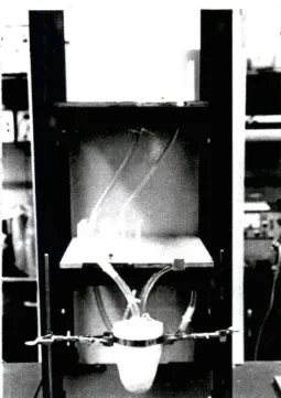
Figure 3.1. A photograph of the bench top set-up used during the
laboratory studies 21
Figure 3.2. Outlet flow (top) and intra-ventricular pressure (bottom) waveforms for the artificial ventricle during assistance by the
fiberglass reinforced silicone rubber conical cuff 23 Figure 3.3. A photograph of the Dacron reinforced silicone rubber
''balloon" cuff and the fiberglass reinforced silicone rubber
"support" cuff 25
Figure 3.4. A recording of outlet flow (top) and intra-ventricular
pressure (bottom) without the support cuff 26 Figure 3.5. A recording of outlet flow (top) and intra-ventricular
pressure (bottom) with the support cuff 26
Figure 3.6. A photograph of the fiberglass reinforced silicone rubber cylindrical shaped cuff and the Dacron reinforced silicone
rubber balloon strap 30
Figure 3.7. A recording of outlet flow (top) and intra-ventricular
pressure (bottom) during assistance on the artificial ventricle
by the cylindrical shaped cuff with bladder 31 Figure 3.8. A recording of aortic pressure before the conical shaped cuff
was placed around the heart (control) 36
Figure 3.9. A recording of aortic pressure after the conical shaped cuff
was positioned on the heart and the bladder was inflated 36 Figure 3.10. A recording of aortic pressure during total assistance by the
Figure 3.11. A recording of aortic pressure (top) and flow (bottom) during total assistance on a fibrillating heart using the
conical cuff 38
Figure 3.12. A recording of aortic pressure (top) and flow (bottom) during total assistance on a fibrillating heart using the
cylindrical cuff 38
Figure 3.13. A recording of aortic pressure (top) and flow (bottom) before the cuff with the partitioned bladder sections was
placed on the heart 51
Figure 3.14. A recording of aortic pressure (top) and flow (bottom) after the cuff with the partitioned bladder sections was
placed on the heart 51
Figure 3.15. A recording of aortic pressure (top) and flow (bottom) during partial assistance (every other beat) on a normal beating heart using the cuff with the partitioned bladder
sections 52
Figure 3.16. A photograph showing the aortic ring with the straps and
supports 53
Figure 3.17. An illustration of the heart cuff with purse-string nylon
"dome" 55
Figure 3.18. A photograph of the inner surface of the heart cuff 57 Figure 3.19. A photograph of the outer surface of the heart cuff 59 Figure 3.20. A photograph of the heart cuff in a cylindrical shape 61 Figure 3.21. An illustration of the heart cuff in position on a heart using
the purse-string nylon "dome" to keep it in place 63 Figure 3.22. A photograph of a heart before the heart cuff was placed in
position 64
Figure 3.24. An illustration of the heart cuff in position on a heart using
the aortic ring and straps with supports to keep it in place 65 Figure 4.1. A recording of aortic flow and mean aortic flow before the
heart cuff was placed on the heart during trial #4 71 Figure 4.2. A recording of aortic and ventricular pressure before the
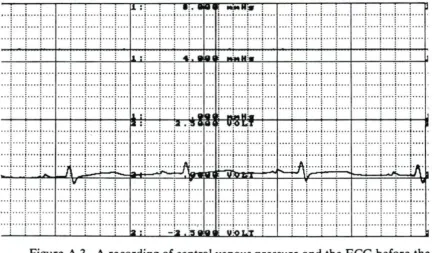
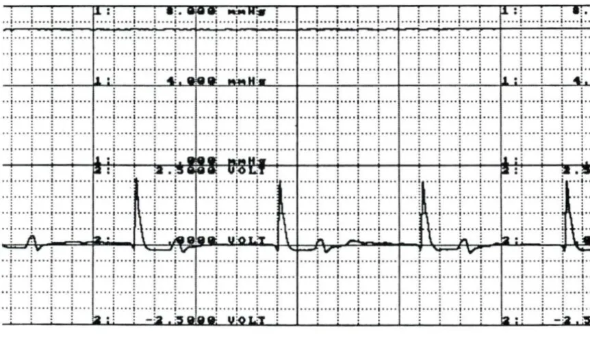
heart cuff was placed on the heart during trial #4 71 Figure 4.3. A recording of venous pressure (top) and the ECG before
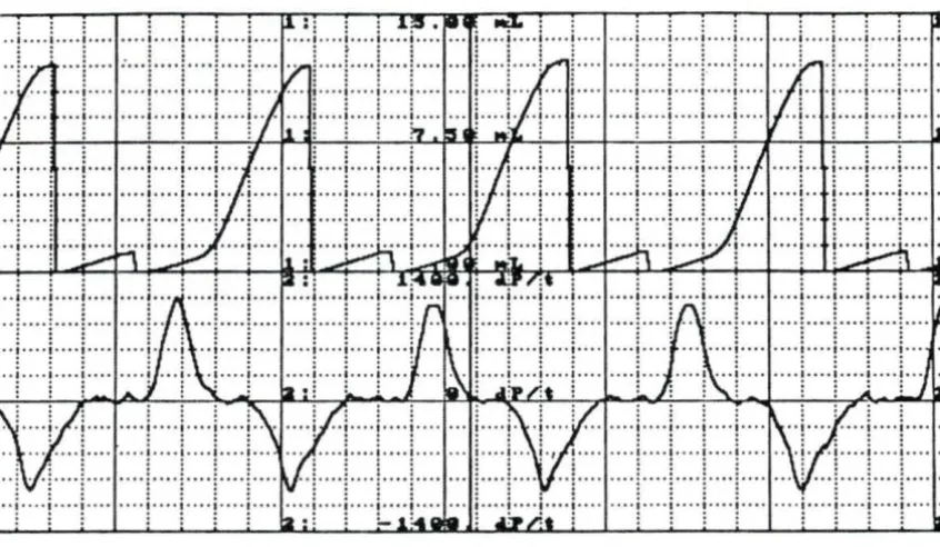
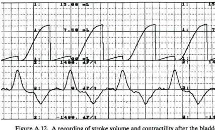
the heart cuff was placed on the heart during trial #4 72 Figure 4.4. A recording of stroke volume(top) and contractility before
the heart cuff was placed on the heart during trial #4 72 Figure 4.5. A recording of aortic flow and mean aortic flow after
assisting every other beat for 30 min during trial #4 73 Figure 4.6. A recording of aortic and ventricular pressure after assisting
every other beat for 30 min during trial #4 73 Figure 4.7. A recording of venous pressure (top) and the ECG after
assisting every other beat for 30 min during trial #4 74 Figure 4.8. A recording of stroke volume (top) and contractility after
· assisting every other beat for 30 min during trial #4 74 Figure Al. A recording of aortic flow and mean aortic flow before the
heart cuff was placed on the heart during trial #2 92 Figure A2. A recording of aortic and ventricular pressure before the
heart cuff was placed on the heart during trial #2 93 Figure A3. A recording of venous pressure (top) and the ECG before
the heart cuff was placed on the heart during trial #2 93 Figure A4. A recording of stroke volume( top) and contractility before
the heart cuff was placed on the heart during trial #2 94 Figure AS. A recording of aortic flow and mean aortic flow after the
heart cuff (bladder empty) was placed on the heart during
Figure A6. A recording of aortic and ventricular pressure after the heart
cuff (bladder empty) was placed on the heart during trial #2 95
Figure A7. A recording of venous pressure (top) and the ECG after the heart cuff (bladder empty) was placed on the heart during
trial #2 95
Figure AS. A recording of stroke volume(top) and contractility after the heart cuff (bladder empty) was placed on the heart during
trial #2 96
Figure A9. A recording of aortic flow and mean aortic flow after the
bladder was pressurized during trial #2 96
Figure AlO. A recording of aortic and ventricular pressure after the
bladder was pressurized during trial #2 97
Figure All. A recording of venous pressure (top) and the ECG after the
bladder was pressurized during trial #2 97
Figure A12. A recording of stroke volume( top) and contractility after the
bladder was pressurized during trial #2 98
Figure A13. A recording of aortic flow and mean aortic flow at the start
of assisting every other beat during trial #2 98
Figure Al4. A recording of aortic and ventricular pressure at the start of
assisting every other beat during trial #2 99
Figure A15. A recording of venous pressure (top) and the ECG at the
start of assisting every other beat during trial #2 99
Figure A16. A recording of stroke volume (top) and contractility at the
start of assisting every other beat during trial #2 100
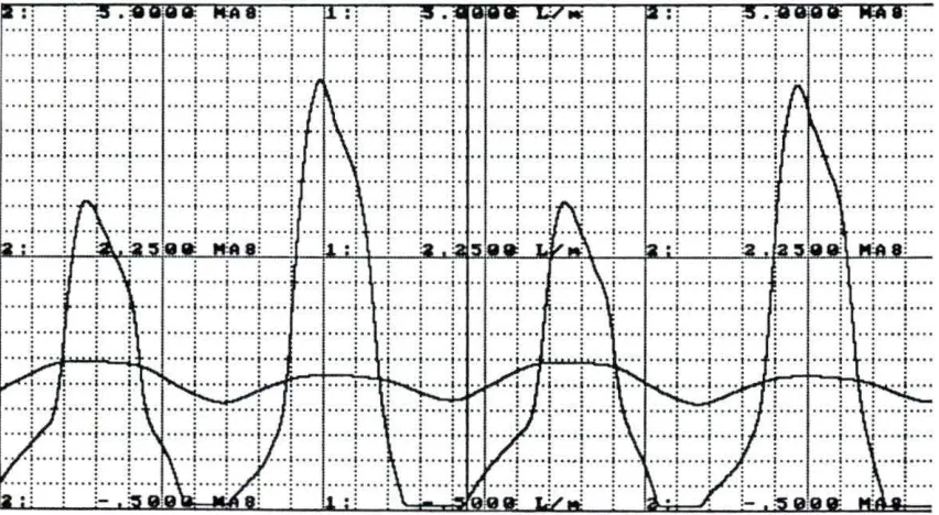
Figure A17. A recording of aortic flow and mean aortic flow after
assisting every other beat for 15 min during trial #2 100
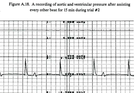
Figure A18. A recording of aortic and ventricular pressure after assisting
Figure Al9. A recording of venous pressure (top) and the ECG after
assisting every other beat for 15 min during trial #2 101 Figure A20. A recording of stroke volume (top) and contractility after
assisting every other beat for 15 min during trial #2 102 Figure A21. A recording of aortic flow and mean aortic flow after
assisting every other beat for 30 min during trial #2 102 Figure A22. A recording of aortic and ventricular pressure after assisting
every other beat for 30 min during trial #2 103 Figure A23. A recording of venous pressure (top) and the ECG after
assisting every other beat for 30 min during trial #2 103 Figure A24. A recording of stroke volume (top) and contractility after
assisting every other beat for 30 min during trial #2 104 Figure A25. A recording of aortic flow and mean aortic flow at the start
of assisting every beat during trial #2 104
Figure A26. A recording of aortic and ventricular pressure at the start of
assisting every beat during trial #2 105
Figure A27. A recording of venous pressure (top) and the ECG at the
start of assisting every beat during trial #2 105 Figure A.28. A recording of stroke volume (top) and contractility at the
start of assisting every beat during trial #2 106 Figure A29. A recording of aortic flow and mean aortic flow after
assisting every beat for 15 min during trial #2 106 Figure A30. A recording of aortic and ventricular pressure after assisting
every beat for 15 min during trial #2 107
Figure A31. A recording of venous pressure (top) and the ECG after
assisting every beat for 15 min during trial #2 107 Figure A32. A recording of stroke volume (top) and contractility after
Figure A33. A recording of aortic flow and mean aortic flow after the
heart cuff was removed at the end of trial #2 108 Figure A34. A recording of aortic and ventricular pressure after the heart
cuff was removed at the end of trial #2 109
Figure A35. A recording of venous pressure (top) and the ECG after the
heart cuff was removed at the end of trial #2 109
Figure A36. A recording of stroke volume( top) and contractility after the
ACKNOWLEDGMENTS
I would like to express my deepest gratitude to Professor Donald F. Young for his constant support and encouragement throughout my graduate program. He has been an excellent teacher and advisor. I would like to thank Professors Thomas R. Rogge and Frederick B. Hembrough for serving on my committee. In addition, I would like to thank Dr. Nikos Stergiopulos and Dr. Raymond K Kudej for their contributions to this research.
I would also like to thank Dr. Ronald Grooters, Dr. Keith L. McRoberts, and the Iowa Methodist Health System for allowing me the opportunity to work on this project. In addition, I would like to express my appreciation to Dr. Grooters for his expertise and suggestions throughout the design and development of the assist device.
CHAPTER 1. INTRODUCTION
The cardiovascular system serves as a transport mechanism for the body. It consists of a four chambered heart and two closed loops- the systemic circulation and the pulmonary circulation. The heart, essentially a pump, is responsible for supplying blood, the transport medium, to each of the circulatory loops. The right side of the heart pumps blood through the pulmonary circulation to the lungs where it receives oxygen from the inspired air and expels carbon dioxide to the expired air. The left side of the heart pumps blood through the systemic circulation to the
periphery and specialized organs such as the kidney and the liver which allow for the adequate maintenance of nutrients and removal of waste products. The supply of nutrients and removal of waste products is essential to maintain the biochemical environment of the individual cells. If the cardiac output is insufficient for
cardiopulmonary bypass machine takes over the function of the heart during the surgery. After the operation, the potassium solution is removed and the heart begins to contract again. If the force of contraction does not appear to be adequate, the surgeon might leave the patient on the cardiopulmonary bypass machine until the heart has recovered further and is contracting stronger. Another option is to use an intra-aortic balloon pump. The intra-aortic balloon catheter is introduced into the descending aorta and is inflated during the diastolic phase of the cardiac cycle. This counter-pulsation helps pull the blood out of the left ventricle during the subsequent systolic phase and thus helps increase the output of the left ventricle. However, extending the time on the cardiopulmonary bypass machine or using an intra-aortic balloon pump is successful only about 50% of the time.
Several devices called artificial left ventricular assist devices or "AL V ADS" are used when the intra-aortic balloon pump offers insufficient cardiac support. The insertion of AL V ADS is a very difficult surgical procedure which involves bypassing the normal pumping of blood by the ventricle into the ascending aorta. Instead, an artificial pump is connected from the ventricular apex to the descending thoracic aorta. Thus, great care must be used to prevent neurological and cardiac damage in these sections of the heart. In addition, AL V ADS are difficult to maintain, and they require high levels of anticoagulants to prevent thrombosis formation on the surface of the devices.
prevent any cardiac rhythmic problems or fibrillation; it should not cause neurological injury and cardiac tissue damage; it should prevent embolization problems; and it should preserve other organ function in the post-operative period.
From a study conducted by Dr. Ronald K. Grooters, a cardiovascular surgeon at the Iowa Methodist Medical Center, it was estimated that at least 6 of 250 patients in a 6 month period might have benefited from such a device. Iowa Methodist, located in Des Moines, Iowa, has a prominent thoracic surgery division where 4 surgeons have performed 3500 open-heart surgeries in the past 12 years.
The purpose of the research described in this thesis was to design, develop, and evaluate a direct mechanical ventricular assist device. Laboratory studies were conducted for the initial design and development phase. Once a final design was achieved that satisfied the desired criteria, a series of animal studies were
CHAPTER 2. LITERATURE REVIEW
In the late 1950s and 1960s, there were several attempts made to develop a direct mechanical ventricular assist device. The main objective of the devices was to
squeeze the heart by applying a force to the epicardial surface thereby acting as a cardiac massager to resuscitate a failing heart. At this time, there was a
considerable amount of research to determine the preferred method of cardiac-resuscitation: closed-chest or open-chest. With open-chest cardiac-resuscitation showing consistently better hemodynamic results, several mechanical devices were developed to take over manual cardiac massage, the standard form of open-chest cardiac-resuscitation. Although most of the mechanical devices performed better than both open-chest manual cardiac massage and closed-chest resuscitation, closed-chest resuscitation remained the preferred method to use since opening the chest to gain access to the heart caused additional trauma to an already weakened patient. By 1970, most research in this area diminished.
One of the first methods attempted to mechanically massage the heart was
performed by Bencini and Parola (1956) using a technique called "pneumomassage". This technique consisted of rhythmically insufflating the pericardial cavity with gas. Since the pericardium is a relatively strong and inelastic membrane, insufflation of the pericardial cavity resulted in compression of the heart, as opposed to inflation of the pericardium.
pressures obtained (680 - 1,125 mm Hg) were well above the estimated pressure required to compress the heart ( < 200 mm Hg).
The apparatus used to introduce the gas into the pericardia! cavity was a specially designed metallic cannula. After the cannula was inserted into the pericardia! cavity through a small hole in the pericardium, a screw device was used to partially seal the hole and to hold the apparatus in place. A gas source was then connected to the cannula.
In order to evaluate the technique, experiments were performed on 20 mongrel dogs. After the thoracic cavity was entered and the heart exposed, ventricular fibrillation was induced without injuring the pericardium. The apparatus was then introduced into the pericardia! cavity, and rhythmic insufflation was started.
Maximal blood pressure in the femoral artery increased from 0 to 50-100 mm Hg and was maintained throughout the period of assistance (up to 60 minutes). A left cardiography showed that the rhythmic compression of the heart did not interfere with coronary blood flow. In each case, defibrillation was achieved after the period of total assistance.
Vineberg (1957) reported the development of a "mechanical heart massager". The device was designed to completely encapsulate the heart using a nylon pouch and to compress the ventricles using two inflatable rubber diaphragms sewn to the interior walls of the pouch. In order to position the device around several different size hearts, two straps of non-stretchable cloth were incorporated into the middle of the pouch, and a drawstring was provided at the top and bottom. The device was slipped underneath and wrapped around a heart, and then the cloth straps were tied to fit the pouch around the heart. The drawstrings were used as adjustments to enclose the top and bottom of the heart, respectively. Since the top drawstring was pulled tightly along the atrioventricular groove of the heart, it prevented the device from slipping off the heart during assistance.
A pump was built to apply the pulsating air pressure to the diaphragms. The pumping action was designed to match the cardiac cycle of one-third systole and two-thirds diastole. Each pump cycle had a one-third positive pressure stroke (inflation) followed by a two-thirds negative pressure stroke (suction). To accommodate different heart rates, the speed of the pump was variable.
This device appeared to be promising, but no further research was ever reported. A possible problem with the device would be the difficulty of completely enclosing several different sized and shaped hearts with only a couple of straps and
drawstrings to ensure that the inflating balloons would be directed into the ventricles instead of just filling the gaps between the pouch and the heart. A low ratio of stroke volume to balloon volume would most likely result especially since, even though nylon is non-distensible, it would still have a tendency to bulge out upon inflation of the diaphragms.
Wolcott et al. (1960) devised a simple, but effective means of artificially
contracting the ventricles. Their "mechanical heart massager" was made with a rigid metal outer shell and a flexible rubber inner liner sealed to the edges of the outer shell. The heart was slipped inside the outer shell and alternating positive and negative pressure was applied to the space between the outer shell and the inner liner by a centrifugal pump. The inward expansion of the inner liner squeezes the heart and subsequent contraction of the inner liner allows the heart to relax for ventricular filling.
The "mechanical heart massager" was demonstrated to be an effective means of resuscitating a failing heart. Unlike the other devices previously mentioned, the "mechanical heart massager" does not completely enclose the heart. The cylindrical shape of the outer shell leaved the apex exposed. This eliminated the need to fit the irregular shape of the heart. Only the circumference of the outer shell and that of the largest cross-section of the heart would have to be matched. However, fitting the circumference of the outer shell to the heart might still require a variety of different sized outer shells. Another problem, which the authors didn't address, was the need to hold the device on the heart, other than manually, for long periods of assistance.
Kline (1962) outlined the development and evaluation of a myocardial prosthetic device in his doctoral dissertation. The device was intended to be used as a chronic fixture on a irreversibly failing heart and to act as an artificial means of cardiac support.
The device consisted of an inelastic, yet flexible outer shell with an expandable inner liner made from Dermoid and Guardex materials. The device was designed to encapsulate the entire heart by inserting the heart into the top opening of the
flexible outer shell. The size and shape of the outer shell was determined through anatomical studies performed on both cadavers and live subjects. Since the heart size varies depending on the weight of an animal, only dogs weighing approximately 10 kg were used to prevent the need for several different sized outer shells to be made. A stem was incorporated into the outer shell to allow gas to enter and inflate the inner liner. Once the device was positioned around a heart, a hole was
trephined in the sternum to allow access of the stem outside the thoracic cavity. It
negative pressures inside the inner liner. The outer shell was form-fitted to the
he~ and the device was prevented from being ejected during assistance since the
top of the shell follows the tapered contour of the atrioventricular groove of the heart. In addition, the device was stabilized since the stem was supported by the sternum.
The performance of the device was evaluated on one mongrel dog. A left thoracotomy was performed to expose the heart. Fibrillation was induced, and the heart was then slipped inside the outer shell. Total assistance was started and the carotid arterial pressure rose from 0 to 95 mm Hg. After 54 minutes of total assistance, the heart was defibrillated, and the subject fully recovered.
One of the problems with this device is the necessity to form-fit the device around a heart of a particular size and shape. This would be suitable if there were enough time to fabricate the device for a particular patient, but during times of emergency, a device would have to be readily available. The individual variances in heart size and shape would require an impractical amount of different sized and shaped devices. Thus, this device would only be feasible if it were used on a patient with imminent irreversible heart failure until a heart transplant could be performed.
Hg) was applied to the inside of the rubber ventricles which caused it to be sucked up against the outer shell. This allowed for ventricular filling. During systole a less negative pressure (100 mm Hg) was applied to the inside of the rubber ventricles which caused it to relax and thus squeeze the heart. To account for slight variations and ensure a proper fit from heart to heart, a thin rubber liner was adhered to the inside of the rubber ventricles. The thin liner was then injected with fluid to fill any gaps between the heart and the rubber ventricles. The base of the rubber ventricles had a "jelly collar" which was designed to fit in the atrioventricular groove. A
separate air line, which connected at the apex and extended through the rubber ventricles, was used to suck the ventricles into the assistor. This was intended to keep the device from being ejected from the ventricles during assistance.
The device was tested on mongrels dogs. After exposing the heart and removing the pericardium, fibrillation was induced; the device was positioned on the heart; and assistance was started. During assistance, the arterial pressure was maintained at 100/70 mm Hg with a heart rate of 110 beats per minute. (The control arterial pressure was 125/95 mm Hg with a heart rate of 150 beats per minute.) The atrial pressures were normal throughout the assistance period which strongly suggests that the assistor was able to maintain a balance between the right and left output of the ventricles. After assisting for an hour, the heart was successfully defibrillated.
Although the device was able to sustain adequate arterial pressure during assistance, examination of the heart showed epicardial abrasions caused by
lining the inside of the thin rubber liner with jelly-like "Sylgard" diluted with Silicone fluid were unsuccessful.
The "mechanical pulsator" was developed in 1966 by Zajtchek et al. It consisted of a plastic shell which enclosed the heart except for an oblong opening near the base which allowed for the passage of the great vessels. The plastic enclosure had a slot running from the base to the apex to allow the apparatus to be slipped into place and then securely closed. A curved rubber bellows was affixed to the inside of the plastic enclosure at the position of the left ventricle. An air line passed through the plastic enclosure and connected with the bellows. Pressure pulses were supplied to the bellows through the air line. A small rubber button fastened to the bellows allowed for fixed angular location.
The device was tested using mongrel dogs. After exposing the heart through a left thoracotomy and removing the pericardium, the device was positioned around the heart. The pump was then started, and the inflation of the bellows was
synchronized with the action of the ventricle by adjusting the inflation and deflation points on the pump. At which time, fibrillation was induced and total assistance begun.
The mean pressures in the femoral artery during assistance ranged from 55 to 105 mm Hg with periods of assistance of 1.5 to 6.5 hr. After the assistance was stopped, defibrillation was successful and each of the subjects fully recovered. Post-mortem histological examination of the heart, lung, kidney, and liver showed no tissue damage.
The most notable direct mechanical ventricular assist device, which is still being researched today, is the Anstadt cup. It was developed by George Anstadt and first reported in 1966 by Anstadt et al. Since then, several researchers have evaluated the Anstadt cup for various applications (Anstadt and Britz, 1968; Coogan et al., 1969; McCabe et al., 1983; Melvin et al. 1973; Skinner et al., 1967b). The Anstadt cup consists of a glass housing with an internal polyurethane diaphragm. The glass housing is formed to fit the shape of the heart. The pneumatically driven device applies alternating positive and negative pressure to the heart through an air line connected to the diaphragm. The device is held in place on the heart by a sustained negative pressure (vacuum) between the diaphragm and the heart through a
separate air line which connects through the apex.
In one study on 11 mongrel dogs, total cardiac support was maintained during ventricular fibrillation on 3 of the subjects for periods of 2-3 days (Anstadt et al., 1971). Subsequent defibrillation was successful and each of the 3 dogs fully recovered. However, all of the dogs showed good hemodynamics throughout the assistance. Complications, such as a mechanical fatigue in the diaphragm and a pneumothorax, prevented the other dogs from surviving the post-operative period.
In one case, where the dog was supported for 3 days, the arterial and venous
pressures were maintained at the initial control values of approximately 100 mm Hg and 5 mm Hg, respectively. The cardiac output ranged from 52 to 83% of the control value. The subject fully recovered and was clinically sound 2 years after the operation.
hours during ventricular fibrillation. After the cardiac support period, the ventricles were defibrillated, and the animals were allowed to recover. Six of the dogs, which were assisted for 6 hours, were sacrificed after 48 hours. The other six dogs, which were assisted for 6 to 24 hours, were sacrificed after 3.5 to 20 months. Immediately following euthanasia, an autopsy was performed, and all the major organs were examined.
All abnormal pathological findings were limited to the heart. In all six dogs assisted for 6 hours and sacrificed after 48 hours, a discrete subendocardial
ecchymosis was present in the anterior wall of the right ventricle. The ecchymoses, which were located 1 to 2 cm proximal to the pulmonic valve, ranged from mild hemorrhages to large hematomata measuring from 2 to 4 cm in diameter. Small foci of coagulated necrosis were found in the myocardium contiguous to the ecchymoses and in the subepicardial zone of all the chambers.
A layer of fibrous tissue was present in the epicardium of the dogs assisted for 6 to 24 hours and sacrificed after 3.5 to 20 months. However, this thickening did not appear to be constrictive. Scars were found in the anterior wall of each right ventricle. These were associated with the ecchymoses found in the six dogs
sacrificed after 24 hours. Only a single microscopic focus of myocardial fibrosis was present in the left ventricle.
The Anstadt cup was the first device to be used for partial assistance on a ''weakened" heart (Skinner, 1971). To simulate a "weakened" heart, the left
circumflex coronary artery was ligated for 5 hours in 13 mongrel dogs. During the ligation, the mechanical assistance was synchronized to the beating heart. Of the 13 dogs, 12 survived 24 hours after the procedure, and 8 survived 1 week. A survival rate of only 33% was found in control animals given supportive treatment. During the synchronized assistance, both coronary sinus flow and myocardial oxygen consumption decreased significantly. This showed evidence that the myocardial work load can be reduced during mechanical assistance.
The Anstadt cup has proven to be an effective cardiac assist device. Several clinical trials on dogs have been conducted over the past 15 years to evaluate the performance of the device and to determine its effects on the heart and the other major organs with promising results. However, only limited clinical trials on
humans have been performed (Baue et al., 1968). A possible reason for the lack of further development and subsequent application to human subjects is the difficulty of fitting the device to hearts of varying size and shape. In several cases, assistance was interrupted because the Anstadt cup was ejected from the heart. This was caused by an improper fitting of the device. In other cases, severe damage was inflicted on the myocardium because the device was too loose. An assist device must be capable of being applied to several different sized and shaped hearts. Otherwise, an excessive number of devices would be required to fit all possible hearts, and application of the device would be cumbersome and time-consuming. In
addition, commercial production of the device would be unfeasible.
a partial assist device with the proper timing circuits to synchronize the action of the device to the beating heart. From a hemodynamics point of view, all of the devices appeared to satisfactorily replace the function of the heart during cardiac
CHAPTER 3. DEVELOPMENT OF THE ASSIST DEVICE
The initial development of the direct mechanical ventricular assist device which is described in this report consisted of deciding upon a list of design criteria and reviewing available materials which could be used to fabricate the device. The second stage of development involved designing and constructing several prototypes. During this early phase, a laboratory set-up with an artificial ventricle was used to evaluate the performance of each design. After a working prototype was obtained, animal studies were conducted for further refinement until the final design was achieved.
From the literature review of problems encountered during previous attempts of direct mechanical ventricular assistance, two basic characteristics of the assist device to be developed were set before the design process was started. First, the device would not enclose the entire heart, since this would require the use of several different sized devices with possibly different shapes. Instead, it would cover the base and mid-section of the heart, and the apex would remain exposed. Second, two localized balloons centered at each ventricle would be used to apply the
flexible but not distensible outer shell containing two balloons in contact with the right and left ventricle, respectively.
Design Criteria
Before the design and development of the assist device was started, the following design criteria were specified to ensure the final design satisfied the required
characteristics.
1. The device should be applicable to hearts of varying size and shape so that only a few different models would be required for all cases.
2. The device should be capable of being quickly and easily placed into proper position on the heart.
3. The device should remain in proper position throughout the assistance period without the use of sutures or suction.
4. The device should not significantly interfere with venous return, arterial output, heart contractility, and/or coronary blood flow.
5. The device should be capable of delivering enough force to adequately pump the heart.
6. The device should cause minimal damage to the heart tissue.
Materials and Equipment
were not feasible, and thus, the materials chosen had to ensure that fabrication of the device was relatively simple.
Two of the main materials used during the initial development of the device were silicone rubber and Silastic medical grade sheeting. These materials were chosen because they can be readily bonded to other silicone rubbers and Silastic sheetings and reactive metals, such as aluminum, using a Silastic Type A medical adhesive. In addition, several types of silicone rubber are available with a range of distensibility. Silicone rubber reinforced with fiberglass (1/ 16 in. thick) and silicone rubber reinforced with a Dacron mesh (1/ 16 in. thick) were tested in the portions of the assist device which were required to be nondistensible, the outer shell and the balloon backing, respectively. Eventually, a sheet of 0.005 in. thick stainless steel was used for the outer shell. In the inflatable sections of the assist device, sheets of non-reinforced Silastic with thicknesses of either 0.01 or 0.02 in. were used.
available for further adjustment and fine-tuning to match the balloon inflation to the contraction of the heart for optimal assistance. The inflation point can be adjusted from 0 to 500 ms after the R-wave, and the deflation point can be adjusted from 3 to 625 ms after the inflation point. In addition, the balloon can be triggered to inflate on every beat, every other beat, and every third beat. The balloon pump system also has an internal trigger which causes the inflation-deflation of the balloon to occur at a constant rate. The rate can be adjusted from 60 to 130 bpm. This is useful during ventricular fibrillation when a ORS complex is not present to trigger the inflation-deflation of the balloon. Another feature of the system is a balloon augmentation dial which controls the amount of gas which is pumped into the balloon. The volume of gas can be adjusted from 0 to a maximum 70 mL. This offers the capability of adjusting the level of assistance.
Although the volumes available for pumping were limited, the use of the intra-aortic balloon pump was very convenient for the initial development of the assist device. The timing circuitry makes it adaptable so that it can be used as both an intra-aortic balloon pump and a pump for a direct mechanical ventricular assist device. Without it, a pump and control unit would have to be designed and constructed. This would have been costly and time-consuming.
Laboratory Studies
Laboratory set-up
The laboratory set-up of the artificial ventricle is shown in Figure 3.1. The artificial ventricle was made from a Dow Corning HS II RTV high strength moldmaking silicone rubber-kit and molded into an approximately conical shape, similar to an actual heart. The rigidity of the silicone rubber was increased by incorporating strips of nylon mesh laterally inside the walls of the ventricle. The top of the ventricle was closed-off using a circular piece of Plexiglas with three openings.
Two of the openings were connected to 5 /8 in. inlet and outlet tubes which
contained one-way valves to ensure flow would only occur in the desired direction. The other end of the inlet tube was connected to the inlet reservoir which had a pressure bead corresponding to the filling pressure of the ventricle. The other end of the outlet tube was connected to the outlet reservoir which had a pressure bead corresponding to the workload required to pump water out of the ventricle. The overflow of the outlet reservoir was directed into the inlet reservoir to make a closed-loop system which would not require a water source. The third opening in the Plexiglass top was used to introduce a catheter inside the ventricle to measure intra-ventricular pressure.
Figure 3.1. A photograph of the bench top set-up used during the laboratory studies
Design process using the artificial ventricle
The final design of the assist device evolved through many different trials. In this
section, a description of this evolution during the laboratory studies is presented. The first prototype built was a simple conical shaped cuff designed to
from a sheet of fiberglass reinforced silicone rubber. It was cut from the sheet so that it could be wrapped around the artificial ventricle, adjusted to the proper size, and then held in position by Velcro straps. The width of the outer shell was 7 cm which covered approximately half of the surface area of the ventricle. An additional Velcro strap was strung over the top of the artificial ventricle and connected to the outer shell on each opposite end. Without the strap over the top, the device would slowly slip off the ventricle during assistance. Two circular patches (5 cm dia.) of 0.01 in. Silastic sheeting, with connecting airlines, were glued to the inner surface of the shell for the balloons. Air was supplied to the balloons through tubes which passed through the outer shell and connected to the balloon pump.
This prototype successfully compressed the ventricle, and a steady flow of water through the outflow tube was observed. A recording of the intra-ventricular
pressure and flow in the outlet tube is shown in Figure 3.2. However, this design was intended only to demonstrate the use of the laboratory set-up. The actual shape of a real heart is irregular, and a simple conical shaped cuff would not fit a heart properly to give efficient pumping action.
The next design consisted of two circular balloons (5 cm dia.) with backings attached to a thin strap. The strap and the balloon backings, which were strengthened with a strip of metal, were made from Dacron reinforced silicone rubber. Dacron reinforced silicone rubber was used instead of the fiberglass reinforced because it was less bulky. Since an actual heart is irregularly shaped, it
2 L/rnin
, .. .,.. ·w ..•.•..••.•. ,, ... , .... ···~r
.... "" ... "" ... , ... "' ...
,fill
!ltl~H,l.:1.~l!i 1~.r~!i ill'l~ii~
1 sec 0
40mmHg
1 sec
0
Figure 3.2. Outlet flow (top) and intra-ventricular pressure (bottom) waveforms for the artificial ventricle during assistance by the fiberglass reinforced silicone rubber conical cuff
backings to rotate around the strap. Thus, the backings did not supply enough lateral support to direct the balloons inward, and the ventricle was not being compressed.
a portion of the air supply to inflate the balloons was being used to compress the ventricle.
A third prototype was then constructed which had three thin straps: one at the top, center, and bottom of the backings. The three straps along with the strip of metal for additional support prevented the backings from bulging outward during inflation of the balloons, but this prototype was bulky and cumbersome. The additional straps made it very similar to the original conical cuff ~ade from
fiberglass reinforced silicone rubber.
Keeping in mind that a cuff with a small width would be easier to fit on an actual heart than a cuff which covered the entire base and mid-section, another conical cuff was built using the Dacron reinforced silicone rubber with a width of only 4 cm (compared to 7 cm previously). Two long rectangular patches of 0.01 in. silicone rubber were adhered to the cuff for the balloons. These "longitudinal" balloons were made so the volume upon inflation would be approximately the same as the 5 cm diameter circular balloons used previously. This ensured a proper comparison of pumping action between different prototypes. When the cuff was placed on the artificial ventricle and the balloons were rhythmically inflated and deflated, the compression of the ventricle resulted in a peak intra-ventricular pressure and outlet flow comparable to the conical cuff made from fiberglass reinforced silicone rubber with circular balloons. However, as before, the center of the cuff bulged outward upon inflation of the balloons.
reinforced silicone rubber cuff during assistance. A photograph of this prototype is shown in Figure 3.3. The additional support from the fiberglass reinforced silicone rubber cuff prevented bulging and larger pressures and flows were observed. A comparison between the flow and pressure waveforms with and without the fiberglass reinforced silicone rubber "support" cuff is shown in Figure 3.4 and 3.5.
The next several cuffs were made using the fiberglass reinforced silicone rubber for the outer shell in order to maintain the necessary support required to keep the full inflation of the balloons directed into the ventricle. As mentioned previously, a fiberglass reinforced conical shaped cuff could not adequately fit an actual heart,
2 L/min
1 sec
40mmHg
1 sec
0
t"'
: •tt
'!'
i i H ' +II ti~ ~ lf;i
I L • •H. f; !!::
, f ' ;! F. , :;c ~
11-I I 1lJi J!
I r' '.., ull . tll J]i f I , .
n b i! 1lrn !ti ,f'f\':. ·t il .i!i', HfL.;'!i.
Figure 3.4. A recording of outlet flow (top) and intra-ventricular pressure (bottom) without the "support" cuff
2 L/min
1 sec
40mmHg
1 sec
0
• j :
mr
1p·· ~+:J t 1L tfH qg =i!i H+ '~ill :.U _ tr. ~1 t!~l n~ ~ r:111?@1 lm Ftri12i1 ·n:
.-.. . .-.. r-. r-.
· oi: 1~ ffi1 1:ili+J1 r:i: iJ<, •11, " _ . m1 ·m
=
,!, Ti:i _ , i · H fiHilli :lJ _ .U~!Et: ;~!'fH !H!;ifr;pffi,1!i1!fli!H i·
¥ h~~ 1lP. I Ii ilH t ~i' :Ei1i!U J.f;: ! i! ril 'l!!! ~;: ~~! 11 nrm. !foITTI' ;,:i1tm i;~ i .
1~: T::~::!i.1 .• rntf.:! lliiJi!~iillE!i . iJ: - l!'J!-E;j ~!l!'W;;i:l::;1t ~i !1.if~t. :m rii! m ;r!l lffl !fF ffi' ilil iT ili 1 1l!'.1'f! !1 ·'! ;:: H· 1' :r: '!:! 'i'i' ..
'tf1.· ;~! ::t ~:t :1 .. ;:~ . .-.. ·t:: ~!I.. . ... !~· Hl-!;~: .. ~ .tffl1~f. '!1. ·f: ,~ 'T'n
and thus, the balloons would not be completely against the ventricles. Upon inflation, part of the balloon volume would be wasted to fill the space between the conical shaped cuff and the irregularly shaped heart. In an attempt to compensate for the poor fit, a bladder was added to the inner surface of the outer shell to fill any resulting gaps. Once the cuff was in position around a heart, the bladder could be inflated with saline until the balloons were adjacent to the ventricles. The
expansion of the bladder was adjustable depending on how much saline was injected so the bladder could fit different shaped hearts. The bladder was made by glueing a sheet of 0.02 in. Silastic along the edges of the fiberglass reinforced silicone rubber shell. A valve was incorporated into the bladder for the injection and removal of the saline.
Since the bladder would make it possible to help fit the cuff to several different shaped hearts, the idea of using long rectangular balloons to decrease the width of the cuff was abandoned, and "localized" balloons were used on subsequent models. Although this would require the width of the cuff to increase back to the original value of 7 cm in order to keep the same balloon volume, the "longitudinal" balloons would have compressed the entire circumference of the heart. One of the main requirements of the device was to have two small "localized" balloons so any
possible tissue damage would be limited to a small area. The "longitudinal" balloons might have caused damage around the entire circumference of the heart.
Using the idea of dividing the cuff into two parts, a "balloon" cuff and a "support"
cuff, the "localized" balloons were kept separate from the outer shell and the
bulged out previously, it was thought that the pressure inside the bladder should keep the majority of the expansion directed into the heart. Since part of the pressure to inflate the balloons is lost stretching the balloon material, it is
imperative that the balloons be as large as possible to prevent unnecessary loss of balloon volume. Thus, a new balloon design was used in which the balloon backings were made into a trapezoidal shape as opposed to a circular shape since the area covered by a circle would be smaller than a trapezoid. A trapezoid was used because the heart is approximately conical, and the circumference of a cone decreases towards the point. Thus, the width of the balloon at the base should be larger than the width at the apex so it the matches the shape of the heart. Two slits were cut into the top of the balloon backing so they could be slipped onto a thin strap of Dacron reinforced silicone rubber. This allowed the balloons to be
moveable. Ideally, the thin strap with the balloons would be placed around a heart; the balloons would be adjusted until they were at the center of each ventricle, respectively; the outer shell would be placed over the balloons; and the bladder would then be inflated until the balloons were adjacent to the ventricles.
This cuff design was placed around the artificial ventricle and assistance was started. Since the outer shell was tailor-made to fit the artificial ventricle, the expansion of the bladder was not necessary. In fact, when the bladder was pressurized, a drop in pressure and flow was observed. This is logical since the bladder would only constrict the ventricle and prevent proper filling.
assistance. The device slips off the artificial ventricle because of the balloon action. The force which compresses the ventricle has a upward component. Thus, the resisting force pushes the cuff downward. In an attempt to counter this downward force, the orientation of the trapezoidal balloons was changed. Instead of placing the longer side of the balloon at the base of the ventricle, it was switched to the apex. This was done because the end of the balloon with the longer side expands to a larger degree than the shorter side. Upon inflation, the balloon would act
as
a wedge between the outer shell and the artificial ventricle and tend to overcome the downward force. When the cuff with the new balloon orientation was put on the artificial ventricle, the inflation of the balloons still caused the cuff to slip off after a few minutes. Thus, the wedge created from the balloon expansion was not great enough, and the balloon orientation was changed back.The next attempt to keep the device on the ventricle was to make the outer shell into a cylindrical shape. When inflated, the bladder would form a wedge between the cylindrical shaped outer shell and the conical shaped ventricle in an attempt to minimize the effect of the downward force caused by the balloons. Once in position, the large expansion of the bladder could still push the balloons against the ventricle for optimum assistance. Since the bladder would have to expand larger at the apex than the base of the ventricle to fill the gap between the conical shaped ventricle and the cylindrical shaped outer shell, the bottom of the bladder was folded under when it was glued to the edge of the outer shell while the top of the bladder was still glued flat. A photograph of the cylindrical shaped cuff is presented in Figure 3.6.
Figure 3.6. A photograph of the fiberglass reinforced silicone rubber
cylindrical shaped cuff and the Dacron reinforced silicone rubber balloon strap
to that of the conical shaped cuff. Since the expansion of the bladder was
adjustable, the cylindrical design should be applicable to an actual heart. Although a cylindrical shaped cuff with a bladder would still eventually slip off an actual heart,
2 L/min
1 sec
0
40mmHg
1 sec
0
•!I • : r, 1:: ·
. l . !! I~ • I 11iH II • Ii • " ~ !IH ! II i:!! ',;:~TI .. !ih 1!:: fi. i.-ii !l
ii· i .:1~ •• 11:, 1 : 'µ !1~1·,1; UH ,, 1tf ,ffi! ng g~;ir, i m1 :ti 1' ,,
.ffi! ii . , 11 rr ~ :.L:fi ~ ~ii· m: fl~ !1r: f!!!Ji/ ;H: gu g1: ~=n~m mi.:::!
ii?-:,; ~! , :El i 1i 1P! ;~r rn'fftl! :!! ill ml !W !tr. a:! lit =1~
w
':l' 1u; :m it~' !~'fl:m
·m !!'E rr.~
;, ;
i•D ~~'fH:tili: ilh 1¥.' :if!-~ § ,,,:m
l! :ili!?:'. !!1": :;;: ;g; !f:. ~=1ff.lr Ht iftl W:.!lii :~; •H1 ;;r ui:r IH 1;;J•,;;:· ,:;: 'iil iiH ilH -IJllHli iii'llii,' ?HO':•;;;:,,,:
Figure 3.7. A recording of outlet flow (top) and intra-ventricular pressure (bottom) during assistance on the artificial ventricle by the cylindrical shaped cuff with bladder
viscous fluid was used, the expansion of the balloons might cause less fluid
displacement. Pure glycerin was added to the bladder instead of saline. When the intra-ventricular pressure and the outlet flow were compared to the results obtained using saline inside the bladder, there was no appreciable difference. Thus, saline was used for the expansion of the bladder in the following designs because it is readily available, and if the bladder developed a leak during assistance on a patient, it should not present a problem.
The conical shaped cuff and the cylindrical shaped cuff both demonstrated adequate pumping action on the artificial ventricle. In addition, both appeared to be capable of fitting several different shaped hearts. Thus, the laboratory
development of the assist device was directed toward animal studies involving assistance on an actual heart.
Animal Studies
During this phase of the design and development of the assist device, animal studies were performed on mongrel dogs weighing between 17 and 28 kg. The objectives of the animal studies were to ensure proper fit of the device on an actual heart; to develop a method of keeping the device in proper position during
assistance; and to further evaluate the pumping action of the device. Since these criteria could not be adequately tested using a laboratory set-up, animal studies were necessary.
The prototypes were initially evaluated on hearts during ventricular fibrillation by setting the balloon pump on internal trigger so the balloons would inflate and deflate at a steady rate. These tests were used to evaluate the effectiveness of each prototype by observing the amount of assistance possible without any heart activity. Once the objectives were partially satisfied and a working prototype was achieved, the device was further tested as a partial assist device on a normal heart by
synchronizing the inflation of the balloons to the contraction of the heart using the ECG trigger and timing circuitry in the balloon pump system.
Sur~cal procedure
into the saphenous vein to administer fluids (lactated Ringer's solution) throughout the operation.
Originally, a median stemotomy was performed to gain access to the thoracic cavity. Following the second animal study, a left thoracotomy in the fifth intercostal space was used because it gave better exposure of the ascending aorta for placement of the flow probe. After the thoracic cavity was entered, the heart was relieved from the pericardial sac by incising the pericardium ventrally.
A surgical cut-down was performed on the left inner thigh to expose the femoral artery. A Millar micro-tip pressure transducer was then introduced into the femoral artery, and the tip was positioned in the descending aorta to measure arterial
pressure. Cardiac output minus coronary flow was measured by isolating the ascending aorta and placing a Transonic ultrasonic 16 mm flow probe (model #16S572) around it. In some of the early trials, the ascending aorta was too small for the 16 mm flow probe, and a good signal was not transmitted to the bloodflow meter. Eventually, a 12 mm flow probe (model #12SB95) was purchased to be placed on the thoracic aorta. However, with this location of the transducer only a portion of the total cardiac output was measured. The transducer control unit (model #TCB-100) and the ultrasonic bloodflow meter (model #TlOl) were
connected to the Astro-Med Dash II strip-chart recorder for a continuous recording of both aortic pressure and cardiac output. After all the surgical cut-downs were performed and before placement of the pressure transducer, heparin (50 units/kg) was injected intravenously to prevent clots from forming on the tip of the pressure transducer.
empty was then placed around the heart and adjusted for proper fit. Another reading was then taken to determine the effect of the device on pressure and flow. The bladder was then inflated until the balloons were adequately pushed against the heart. Another recording was taken. Ventricular fibrillation was induced by
applying a low voltage alternating current directly to the myocardium. Immediately following fibrillation, assistance was started using the internal trigger on the balloon pump system. The rate of inflation ranged from 50 to 100 bpm with a total inflation time of 300 ms. A continuous recording was taken throughout the assistance period which varied depending on the performance of the prototype.
the majority of the cuff development while the cuff design changed from experiment to experiment. This prevented the need for several different sized and shaped cuffs to be fabricated for each new prototype.
Desiim process for the outer shell and balloons usin~ total assistance
The first few trials were used to experiment with the fit of the balloon strap and the outer shell and to determine the pumping action of the conical shaped cuff. In
one trial when· the balloon strap and the outer shell were positioned around the heart and the bladder was inflated, the aortic pressure dropped from 65/45 mm Hg to 40/30 mm Hg. (The 16 mm flow probe was not working properly at this time because it was too large to fit the ascending aorta so no measurement of aortic flow was available.) Readjustment of the balloon strap and the outer shell to increase pressure had no effect. However, pressurization of the bladder had a drastic effect on the pressure depending on the degree of inflation. The drop in pressure was believed to be caused by the extra weight of the cuff on the heart and the
constriction of the ventricles by inflation of the bladder. The recordings showing aortic pressure before and after the device was placed on the heart are shown in Figures 3.8 and 3.9
When ventricular fibrillation was induced and total assistance was started, the aortic pressure increased from 0 to 40/32 mm Hg-- the pressure before fibrillation. A recording of aortic pressure during total assistance is shown in Figure 3.10. These pressures were maintained throughout the assistance period of 15 minutes. During this time, the cuff was held in place on the heart manually. Although these
40mm Hg
1 sec
0
Figure 3.8 A recording of aortic pressure before the conical shaped cuff was placed around the heart (control)
1irn 1 ~, 11 I! ! i ill! 111· 1i1 i!I, il'! i . ,; m: Hu
rn
Fit !!Ii;:!::::: ::1 l!lli14 :~ . ~11 ,. !Pi m1 m , 1 ! !i!i l!ll Ill !ll' ::11
< :',:
'!!i 11140mmHg !}!1 l :~ ! i I : I :I !lit! I ! ! !!!: :!:: . ! 1~!i •!I ,lg f':' !iij T .: .. :. l!i'
l!I ·;:!!'ii!,. 1 i'i! '11t:::1;1: i'i' !!! !ti, 1 Hli11 'iii!: "' ;p: ;n! :!'; :;' 1: • ' 1
: .µ :ill I i !, Hi; ! Iii: !I! :1!! !Iii 1!;! Ii h" Ii i 'i!i g· , .. :
:rn
:;'! :1,: ;::, .,, •. : : :: !Ii\ ' ~· 'lli'. :11 ~ 1l1 'Ii ! th I .·: IW '•i! ii'! !!ji ;;;: :.'i j!].;'!iii
• I !; :: '· :tt.1 1 !I•! :i: 1' .. 1!!i ,::'tjj ~i!!!!i'li!'fl!!'!:l
1 sec .c11 1i' r i 1 l"!i: tF,~Hn m: il!i 'ii' 1:1
: j Ii!; ; lb I ~ 1JI! · , ·~ 1 1:1; i;j i~[ l!flj ;~g ;j! rili! l!i'
0
Figure 3.9 A recording of aortic pressure after the conical shaped cuff was positioned on the heart and the bladder was inflated
!I lJ l!tl! .
Ii 1 I
. . •:p 1 l 11
40mmHg . I 1 • ·iJ
iii 1;
ij~ I J.
1 sec !. !1 i IJl UI ! !·
0
Investigation of the balloons during assistance showed that each balloon was not expanding to the expected volume of 20 mL upon inflation. (The balloon pump is capable of compressing 70 mL of air into a total balloon volume of 40 mL.) Since the size of the balloons had to be decreased to match the smaller sized cuff, the possible expansion of the balloons was limited. The balloon pump could not supply enough pressure to stretch the patch of 0.01 in. Silastic sheeting to a volume of 20
mL Instead, the air supplied was being compressed into a smaller volume. Hand massage was performed after the assistance period to demonstrate that larger mean pressures and pulse pressures are possible when the heart is squeezed more forcibly. The aortic pressure was increased to 75/30 mm Hg which was larger than the control value.
In order to compress the heart more forcibly, the balloons needed to expand to a larger volume. Originally, the balloons were made by glueing a sheet of 0.01 in. Silastic flat along the edges of a piece of Dacron reinforced silicone rubber. To increase the expansion of the balloons, the sheet of 0.01 in. Silastic was folded under before it was glued to the top and bottom edge of the balloon backing. The right and left sides were still glued flat. In addition, the width of the cuff was increased from 4.5 to 5.5 cm which allowed the balloon size to increase accordingly. With this increase in width, the cuff covered about two-thirds of the surface area of the heart. These modifications greatly increased the expansion of each balloon from
approximately 10 to 17 mL.
40 mm Hg
1 sec
0
I . I ! lifl ! 1!
4 L/min ! . ' : . ' . ' 111 . . ' : : : ! I !i ! ~ I ! ! . ! I! ! I fl !I !! ! ! : I
1 sec
l i!l I I Ii iii j' ii I i J!ll 1ill l!jj ! j 11;; !l!i ;!j l i I i
fHHl~+H+!i~
I! I. I I ii I ll:i I i 1i Iii II :;!I 1ld :!I Ill' iii .
fH+!l·Hi, +HI +t+H,111+'1l·~111 ! i !1 Iii!' l! 1::1 ! ! :l! .iii iii! H!I !:Ii i!1: ill• ll ! i! I lj,j
!:, I I !7.1111 l•ll 1:1'·." 1Hii1:i1!i 1.: 1i·@iIT111:!'i:1!l!1'il:!' i1li1'1:i:!1i!'
1 .. :1 ' . . ljj . ... ! •. " ,1 .. .. , l .. ;i •.• . ,1 . . ... :111
L . i •f.i ;l!J ! !!I Iii i(; ~!11i!l i!i! 'Hi i:1! ~ i 1i!il iili 11 I :ii! IK !ill;!!! l!;i !ill
I J, 11! \il ii! ri ' li\'
:::i'
1i:i illW +u iii~ ii:i p,!11i µ1; ,iJi '!ii ii!; ::::'iU'0 \. v
Figure 3.11. A recording of aortic pressure (top) and flow (bottom) during total assistance on a fibrillating heart using the conical cuff
40mmHg 1 sec 0 4 L/min 1 sec 0
!Ii .ii! !Il l!! lill Ill II Ill! !!ill~!! l!I !!l!IJ~!f!i!!! I IW !l!!lll!i I!!: :!:i ::!!
!!~ dii !!!: ;;; :lil ·; 111 1 : !i:• 1i11!i: :lH ! liP. :,ii g:: i1'1 ri81i
;rn
i:ii r.;: ;,;: :!:: W Ei! i:i! '!I !I; i .I;!!! iii ;iii! I! I l iil Hi iii' ii'ili;ii l i i!li iii! H!i !?· :; 'i~'.i.i rrr w1 ii 1:1 1 : 1:i 1111 • 11: ii rn Iii n · r ii · 1n P! 11w n:· .;, :i•
1P :i I • • •!
·ni, ·
.1 • ·11rn
H 1··n
PP !Pi :i;; .':: ::i:'l 1 I I I j 11 II JI 11' J l • I !I ri! i:ii iiil
u.f "! , ' '. ! , , I J' • ! . 1\4· i:t f!j l 1f r\' n jl Ill' Ji!
m:
j!i; IH#++++Hl+++!!ff+"+'.H I; ',ii' '.Iii!" ;;· ., ti l ": ·;, ::.· ·~,' 1: i 111 I "" I I l "ll! :ii ill Ii, ti I ll1i11,. IEi1llJ l1!! ii!
tiH iiH if. Iii 1 I
in! ii !1 ' I I'
:;; I ij I!
ii i 1!1, i
!! ! 1· l
. i' Ii
I!'
: l.r,
II it i! ! II
I I hil
Ii
!i
.11 I
. ii I 11 Ii p : 11· I. ;I : : Ill! I! 1id l:: ::., ::'.: i'!l .. 1,;L 1i1 ! I ii 'ii ii !i ii I Ii !II'..:.: iiii
: l •:n. t 1 l . I !II :i:: jjl 11 : : ! I :::: ;iU !Ii
f Ii I~! Ill ~j II' l!i iii! I 1 Ii il iii
The aortic pressure for the conical shaped cuff was 40/30 mm Hg while the aortic pressure for the cylindrical cuff was 60/40 mm Hg. The original control reading was 85 /65 with a pulse pressure of 20 mm Hg. Although the mean pressure for the cylindrical cuff was lower than the control value during total assistance, the pulse pressure was equal. The mean aortic pressure was even lower with the conical cuff and the pulse pressure was only 10 mm Hg. Thus, the pumping action of the cylindrical cuff was significantly better than the conical cuff.
During the trials comparing the conical cuff and the cylindrical cuff, it was very difficult to keep the balloon strap in the same position as the outer shell. The balloon strap continually slid around between the heart and the outer shell.
Eventually, the balloons moved and they were no longer centered on each ventricle. To prevent movement of the balloons, the balloon strap was fastened to the outer shell. The balloon strap was not connected to the outer shell near the balloons so the balloons could still be adjusted until they were at the center of each ventricle. This partially solved the problem, but the balloons were still able to move around since the balloon strap was not connected to the outer shell near the balloons.
Finally, to solve this problem, the balloons were fastened directly to the outer shell, and the balloon strap was removed. Although this prevented adjustment of the balloons, another method could be developed, if necessary, so that the balloons could slide along the top of the outer shell for proper positioning. However, the balloons only needed minor adjustment once the balloon strap was placed on a heart, and thus, the need to position the balloons may not be necessary as long as the balloons are close to the center of the each ventricle. The deletion of the balloon strap removed some of the bulk and weight from the device. The bulk and weight of the device was one of the reasons the aortic pressure dropped when the device was placed around a heart.
Desi~ process for attachment of the device to the heart using total assistance
for periods of up to 30 minutes. However, the pericardium is subject to fatigue, and therefore, it would not be a reliable means of keeping the cuff on the heart during long periods of assistance. One of the design criteria for the device was the ability to remain in position on a heart without the use of the pericardium. Thus, this method was not considered a permanent means of cuff support.
One of the first attempts at holding the cuff in place on the heart consisted of a strap made from Dacron reinforced silicone rubber with five strips of umbilical tape connected to it at equal intervals. The strap was intended to be wrapped around the atrioventricular groove into a ring shape. Since the heart starts to taper at the atrioventricular groove, the ring would be prevented from sliding downward off the heart. After the ring was in position, the five strips of umbilical tape were clamped at the respective locations to the cuff.
Although this method was successful in keeping the cuff in position during most of the assistance period, the aortic pressure was considerably lowered when this method was implemented. The drop in pressure was most likely caused by the downward force on the ring in the atrioventricular groove which prevented the cuff from being ejected from the heart. This force probably caused a partial occlusion of one or both of the low pressure vessels terminating at the base of the heart, the vena cava and the pulmonary vein. This would inhibit ventricular filling and lower the ventricular pressure. In addition, the attachment of the umbilical tape at the anterior of the cuff was very awkward. Since this method interfered with normal heart function, it was considered to be an unsuccessful attempt of keeping the cuff in place on a heart.
shell. After the cuff was wrapped around a heart, the strip was inflated with air. The strip formed a tear-drop shape which extended over the base of the heart. Since the base of the heart tapers off at the atrioventricular groove, the expanded strip would be supported by the base of the heart, and the cuff would be prevented from slipping downward.
This method was unsuccessful. The inflated strip prevented the cuff from being completely ejected from the heart, but the cuff still moved downward. After 10 minutes, the cuff was out of position and the balloons were no longer centered on each ventricle. However, in previous experiments, the base of the heart had a tendency to bulge outward upon inflation of the balloons, especially at the pulmonary conus. With the expansion of the strip, the base of the heart was contained in the device and no bulging was observed. This was verified in the pressure and flow recordings. The cuff with the inflatable strip produced a larger aortic pressure and flow than the cuff without the inflatable strip; the aortic pressure was increased from 22/14 to 30/16 mm Hg while the peak aortic flow was increased from 2 to 3 L/min. Even though this method was unable to keep the cuff in proper position, it did show the advantage of containing the base of the heart to increase total compression.
Keeping in mind the importance of containing the base of the heart inside of the assist device to prevent bulging of the pulmonary conus, a new method was
umbilical tape was pulled tight over the base of the heart where it tapers, the cuff would be prevented from moving downward. In addition, since the nylon "dome" contained the base of the heart, the pulmonary conus was constrained.
When this method was tested, the nylon purse-string "dome" kept the cuff in position during the entire assistance period of 30 minutes with no indication that the
cuff was moving. When the umbilical tape was pulled tight, there was no change in
aortic pressure or flow. Therefore, it was not occluding any of the low pressure vessels terminating at the base of the heart. In addition, the nylon "dome" prevented the pulmonary conus from bulging out. This was verified through observation. To further evaluate this method, it was tested during the remainder of the animal trials.
Design process for the bladder using total assistance
Throughout the animal studies, the prototypes had a significant effect on the aortic pressure and flow when they were placed on the heart and the bladder was inflated. In some cases, the aortic pressure dropped to 50% of the control value while the aortic flow dropped by as much as 60% of the control value. In order for the assist device to be used on a ''weakened" heart, the drop in pressure and flow had to be minimized. Otherwise, the device would have a damaging effect, and the condition of the heart would further deteriorate.