International Journal of Innovative Technology and Exploring Engineering (IJITEE) ISSN: 2278-3075, Volume-8 Issue-6S, April 2019
Abstract: DC-grid has become more popular and became an efficient alternative for DC-grids.AC output of wind generator is applied to a dual buck boost converter. The DBBC is filtered using CLL filter.Our work mainly focus onnano-grid system with PRC and Fuzzy Logic controllers. The performance of NGS with PRC and FLC are compared and their results are presented. The results indicate that FLC controlled DBBC gives superior response.
Index Terms: DC Nano-grid, AC/DC Converter, Buck- Boost, PR, Fuzzy Logic Controller.
I. INTRODUCTION
Renewable energy sources based onDC micro-grid uses an ultra-capacitor and battery has been investigated. To improve the depth of penetration advanced technology is used into the utility grid. Ultra capacitors are used as voltage source to support both connected and islanding mode. DC nanogrid for renewable sources with modular DC/DCLLC converter building block is suggested by Cecati.
Brought together power frameworks are being coordinated by a huge number of little disseminated age bunches, called nanogrids, equipped for guaranteeing full usage of sustainable power sources, high adaptability, proficiency and improved unwavering quality of the power network because of redudancy. In this investigation, little photovoltaic plants joined with vitality stockpiling frameworks speak to a promising answer for full abuse of sustainable power sources and for successful advancement of electro versatility. The motivation behind this examination is two-crease: first it manages a DC nano-network reasonable for little vigorous groups, for example, private or places of business and comprising of photovoltaic clusters, power devices, electric vehicle charger stations, loads, at that point proposes a multifunctional full-connect DC/DC LLC resounding converter building. Practically all little scale inexhaustible generators produce low voltage DC control. To supply capacity to the AC mains organize, expensive and wasteful power invertors/convertors setups are utilized. In any case, the created power from such sustainable power sources may convey to a DC load.
Revised Manuscript Received on April 10, 2019.
K. Hemavathy, Assistant Engineer, CERC, TANGEDCO, India
AnithaSampthkumar, Assistant Professor, EEE Department, BIHER, BIST, Chennai 600 073, India
S.Prakas, Professor, EEE Department, BIHER, BIST, Chennai 600 073, India
A conceivable arrangement that can exclude the utilization of exorbitant and wasteful power invertors/convertor setups is to introduce a DC organize connecting the DC gadgets to DC control supplies. This paper is to create ideas and a framework of DC nano-arrange for a Smart Home, made out of: a home territory connect with a Smart Meter and Intelligent Devices.
DC Nano grid system for United ground system
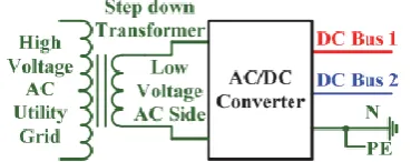
[image:1.595.327.532.315.402.2]In this arrangement, the AC low power framework and the DC Nano-matrix utilize a similar ground line.
Fig. 1 Typical AC/DC converter for the united grounding configuration based DC Nano grid system The benefit of the unified establishing design is that the DC Nano-lattice can without much of a stretch be introduced into the first low voltage AC control network to frame a mixture control framework. The weakness is that because of the low voltage gadgets, the greater part of the first low voltage AC control frameworks can't embrace this design and offer a similar ground line straightforwardly with a DC Nano-lattice, if no extraordinary or entangled AC/DC converters are received.
Dynamic vitality the board of miniaturized scale networks utilizing battery super capacitor joined. The vitality stream among source and the heap of small scale lattice must be adjusted to have a steady dc framework voltage. Because of discontinuity in the normal sources and the varieties in burden, vitality balance task requests stockpiling. The usually favored decision of vitality stockpiling in miniaturized scale matrix is valve directed lead corrosive batteries. The miniaturized scale framework is a way to deal with settle circulated ages interconnecting with power lattice. Wind-PV-ES crossover framework could make full utilization of clean vitality and have high dependability. Smooth exchanging between framework associated and islanding mode is vital to miniaturized scale network stable task. This paper proposes an improved control system consolidating expert slave control with
Closed Loop Control of Dual Buck-Boost AC/DC
Converter for DC Nano-Grid using
Fuzzy-Logic-Controller
Controller
shared control so as to make progress between matrix associated and islanding mode smoother.Unidirection ground System
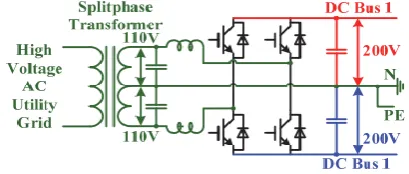
[image:2.595.78.263.235.308.2]As depicted above, because of the low voltage point of confinement of the gadgets, it is troublesome for the DC Nano-matrix to utilize a similar ground line of the low voltage AC control framework. Numerous papers are thinking about the unidirectional establishing arrangement to develop a DC Nano-matrix. Fig. 2 demonstrates a unidirectional establishing setup based DC Nano-network with twofold DC transport and the establishing. In this arrangement, the DC Nano-matrix retains the power from the high voltage AC utility network through a stage down transformer, which works like a detached transformer.
Fig. 2 Unidirectional grounding structure of DC Nano-grid
Since the progression down transformer offers a reasonable low voltage for the DC Nano-matrix, this AC voltage is for the most part lower than the standard AC voltage. For instance, a three-stage venture down transformer may yield a 200 V stage to stage voltage as opposed to the institutionalized 380 V voltage. The AC/DC converter exchanges the AC control into the DC control as the required DC voltage yield and power rating. For instance, the DC Nano-matrix can be a solitary DC transport based framework.
The dynamical attributes of a low voltage MicroGrid from network associated mode to islanded mode with various circulated generation(DG) arrangement plans are broke down by utilizing re-enactment method, and the comparing changing laws of every DG's power, voltage and recurrence of MicroGrid are obtained. When small scale turbine-based synchronous generators are utilized as the principle control support, the recurrence of MicroGrid vacillates greatly, and a few DGs are detached from the matrix by the low recurrence relays, Swhich isn't helpful to stable activity of the MicroGrid.
In network associated task, voltage of DC transport is kept relentless by inverter and voltage and recurrence of AC transport are the equivalent with utility matrix. Vitality Management System controls half and half stockpiling framework to discharge or retain control with the procedures as indicated by lattice condition, condition of charge of batteries and super-capacitor, power cost, etc. In islanded activity, voltage of DC transport is constrained by capacity framework and plentifulness and recurrence of AC-Bus voltage are managed by parallel inverters with voltage-recurrence or hang control procedure.
The circulated ages association planning Algorithm, that take the capacity inverter control display as the center, Based on ultra-momentary anticipating of dispersed ages yield by methods for BP neural system. It ensured small
scale matrix transport voltage to accomplish "zero irregular" amid miniaturized scale framework exchanged from network associated with island mode when city lattice appearance blame.
Characterizing Control Strategies for Micro-Grids Islanded Operation. This paper depicts and assesses the attainability of control procedures to be embraced for the activity of a microgrid when it winds up confined. Typically, the microgrid works in interconnected mode with the medium voltage organize; in any case, planned or constrained seclusion can occur.
A high-recurrence connect single-arrange PWM inverter with basic mode voltage concealment and source-based replacement of spillage vitality. A solitary stage bidirectional high-recurrence transformer (HFT) interface dc/air conditioning converter topology for a three-stage flexible size and recurrence PWM air conditioning drive. This kind of converters locate a wide scope of uses including UPS frameworks, drives including sustainable power sources (Solar, Fuel cell), and vitality stockpiling frameworks (ordinarily low voltage dc to high voltage PWM air conditioning). The HFT results in decrease in expense and weight alongside an impressive increment in power thickness.
Early wind turbines utilized for performing mechanical work (siphoning, pounding and cutting) enhanced optimal design by being permitted to keep running at variable speed. Probably the soonest DC electric breeze turbines were permitted to keep running at variable speed. With the appearance of grid‐connected AC turbines, rotational paces were restricted so as to control the breeze turbine AC recurrence yield to rise to the framework recurrence. With the approach of semiconductor gadgets, endeavors started as right on time as the 1970s to permit variable‐speed activity of large‐scale turbines.
Worldwide most extreme power point following of adaptable photovoltaic modules. In this paper, the impact of geometrical establishment parameters of adaptable PV modules, for example, the bowing edge, tilt point, and introduction, on the state of the power-voltage trademark is tentatively researched. At that point, another strategy for following the worldwide MPP of adaptable PV modules is proposed. An exploratory, near examination is additionally introduced, which exhibits that contrasted with the past-proposed MPP following (MPPT) strategies, the framework proposed in this paper is able to recognize the worldwide MPP of an adaptable PV module with less inquiry steps.
The above literature does not use DBAC for nano-grid. This work proposes DBAC for nano-grid. The comparison of performance of DBACS with PR and FLC is not reported in the previous papers.
II. SYSTEMDESCRIPTION
Block diagram of existing system is shown in Fig.3. AC output of wind generator is applied to a dual buck boost converter. The output of DBBC is filtered using CLL filter. The output of filter is applied to the DC load. The control circuit gives pulses required
International Journal of Innovative Technology and Exploring Engineering (IJITEE) ISSN: 2278-3075, Volume-8 Issue-6S, April 2019
Fig. 3 Block diagram of existing system
Fig. 4 Closed Loop PR Controlled NANO Gird System Closed Loop PR Controlled Nano Gird System is shown in Fig.4. AC output of wind generator is applied to a dual buck boost converter. The DBBC is filtered using CLC filter. The output of filter is applied to the DC load. The load voltage is sensed and it is compared with the reference voltage. The error is applied to a PR controller. The output of PR controller is used to generate the updated pulses. Figure 5 Closed Loop FLC Controlled NONO Gird System
Fig. 5 Closed Loop FLC Controlled NONO Gird System
III. SIMULATIONDESCRIPTION&RESULTS Dual Buck-Boost AC/DC Converter based DC Nano Grid Closed loop system with PR controller is appeared in Fig 6.
Fig. 6 Closed loop DCNGS system with PR controller
The input voltage is appeared in Fig 7 and its peak value is 70V. The Output voltage at load-1 is appeared in Fig 8 and its value is 28V.
Fig. 7 Input voltage
Fig. 8 Output voltage at load-1
The Output current at load-1 is appeared in Fig 9 and its current at load-1 value is 0.55A.The Output power at load-1 is appeared in Fig 10 and its value is 20Watts
Fig. 9 Output current at load-1
Fig. 10 Output power at load-1
The Output voltage at load-2 is appeared in Fig 11 and its value is 30V. The current through load-2 is appeared in Fig 12 and its value is 0.55 A. The Output power at load-2 is appeared in Fig 13 and its value is 20watts.
Fig. 11 Output voltage of load-2
Fig. 12 Output current of load-2
Time in Sec
V
o
lt
a
g
e
V
o
lt
a
g
e
Time in Sec
Time in Sec
A
Time in Sec
Wa
tt
s
Time in Sec
V
o
lt
a
g
e
Time in Sec
A
Time in Sec
Time in Sec
Controller
Fig. 13 Output power at load-2
Dual Buck-Boost AC/DC Converter based DC Nano Grid Closed loop system with FLC controller is appeared in Fig 14. The load voltage is sensed and it is compared with the reference voltage. The error is applied to a FLC controller. The output of FLC controller is used to generate the updated pulses.
Fig. 14 Closed loop DCNGS system with FLC controller
Fig. 15 Input voltage
The input voltage is appeared in Fig 15 and its peak value is 70 V. The Output voltage at load-1 is appeared in Fig 16 and its value is 28V.
Fig. 16 voltage across load-1
The Output current at load-1 is appeared in Fig 17 and its current at load-1 value is 0.55 A.
Fig. 17 current through load-1
The Output power at load-1 is appeared in Fig 18 and its value is 20watts
Fig. 18 Output power at load-1
The Output voltage at load-2 is appeared in Fig 19 and its value is 28V. The current through load-2 is appeared in Fig 20 and its value is 0.55 A.
Fig. 19 voltage across load-2
Fig. 20 current through load-2
The Output power at load-2 is appeared in Fig 21 and its value is 20watts. It can be seen that the output voltage, output current and output power are regulated after one oscillation.
Fig. 21 Output power at load-2
The comparison of time domain parameters is given in Table 1. The real time is reduced from 0.40 Sec to 0.02 Sec; the peak time is reduced from 0.41 to 0.028 Sec; the Settling time is reduced from 0.47 to 0.12 Sec and steady state error is reduced from 1.8 to 0.7 Volts by replacing PR controller with FLC-controller. Dynamic response is also improved by using Fuzzy logic-controller.
Table. 1 Comparison of Time Domain Parameters Types of controller Tr(s) Tp(s) Ts(s) Ess(V)
PR 0.40 0.41 0.47 1.8
FLC 0.02 0.028 0.12 0.7 Time in Sec
Wa
tt
s
Time in Sec
V
o
lt
a
g
e
Time in Sec
V
o
lt
a
g
e
Time in Sec
A
Time in Sec
Wa
tt
s
Time in Sec
V
o
lt
a
g
e
Time in Sec
A
Time in Sec
A
Wa
tt
International Journal of Innovative Technology and Exploring Engineering (IJITEE) ISSN: 2278-3075, Volume-8 Issue-6S, April 2019
IV. CONCLUSION
Dual Buck-Boost AC/DC Converter based DC Nano Grid Closed loop systems with PR and Fuzzy Logic controllers are modeled and simulated using simulink. The performance of NGS with PR and FLC are compared and their results are presented. The settling time is reduced from 0.47 to 0.12 Sec. The steady state error in output voltage is reduced from 1.8 V to 0.7 V using FLC. Therefore the response with FLC is superior to the response with PR controller.
The scope of the present-work is to compare PR-controlled-DCNGS with FL-controlled DCNGS-system. The comparison of FL-controlled DCNGS-system with SMC-controlled-DCNGS-system will be done in near-future.
REFERENCES
1. Jayalakshmi.V and Dr.N.O.Gunasekhar, “Mitigation of Voltage Sag by Dynamic Voltage Restorer using Single Phase Z Source Inverter,” in nternational Journal of Applied Engineering Research, 2014.
2. S. Prakash &K.Sakthivel, “Efficient Transformer less MOSFET Inverter for Grid-Tied Photovoltaic System”, International Journal of Pure and Applied Mathematics, Volume 119 No. 12 2018, 7787-7796. 3. S. Prakash& DEEPAK TOPPO,“ Simulation Results Of A High
Step-Up Dc To Dc Converter Under Fuzzy Logic Control For Solar Cell Power System”, International Journal of Pure and Applied Mathematics, Volume 119 No. 12 2018, 7839-7846.
4. Ms.S.Sherine, Dr.S.Prakash, Mr.A.Navaneethamoorthy,”Investigation on Solar Panels with and Without Shading Effects in Series and Parallel Connections”, International Journal of Engineering and Advanced Technology ,ISSN: 2249 – 8958, Volume-8 Issue-3, February 2019