International Journal of Innovative Technology and Exploring Engineering (IJITEE) ISSN: 2278-3075, Volume-8, Issue- 6S4, April 2019
Abstract— In many Industries, the fault tolerant control scheme have been accepted and used from many decades. In this paper, the observer and the observer based Controller is designed for the three tank interacting system. Initially in this work, the three tank interacting system with Single Input Single Output configuration is modeled and conventional PID controller has been implemented, finally the performances are analyzed. Then the observer is designed for the three tank interacting system. In- order to design the observer based controller, the control law and the feed forward gain value is calculated and described by Chakrabarti A et al.[4]. Finally the observer based controller performances are also analyzed. In this work, the sensor is replaced by the state observer. The observer based controller provides better performance than the conventional PID controller. This work may lead to design fault tolerant control for three tank interacting system in future.
Keywords— Fault Tolerant Control, Conventional Proportional Integral Derivative Control, Observer Based Controller, Three Tank Interacting System, Single Input Single Output.
I. INTRODUCTION
Fault detection and diagnosis is the main component of several operations management automation systems. A “fault” is the other name for a problem. A “root cause” fault is a basic, underlying problem that may cause problems like observable symptoms. (It might not be directly observable). Generally, The root cause is also related with procedures for repair. A "fault" or "Mistake is not needed to be the final result of a complete failure of a part of the System or the specific hardware or device. A fault, Mistake or a problem may be defined as an non-optimal operation or not most desirable product. In a process plant, the main reason of not most desirable operation may be due to hardware failures, but problems might also be caused by operating targets of improper choice, buildup of coke, not proper feedstock quality, poor tuning of controller, partial loss of catalyst performance, low steam system pressure, calibration of sensor errors, or human error. In many Industries, the fault tolerant control scheme have been accepted and used from many decades. Initially the fault tolerant control was realized by hardware redundancy in most of the industries. But due to some limitations like high cost and occupying more space, analytical redundancy have been emerged over the last two
Revised Manuscript Received on April 12, 2019.
Shangkavi G, Assistant Professor ,Department of Electronics and Instrumentation Engineering, SNS College of Technology, Coimbatore, T.N, India. (E-mail: [email protected])
Prabhakaran M, Assistant Professor, Department of Electronics and
[image:1.595.320.534.325.543.2]decades. In this paper, the problem of state estimation and fault tolerance is investigated for the three tank interacting system with Single Input Single Output configuration by designing the observer and observer based Controller. And this Controller is designed using feed forward gain and control law described by Chakrabarti A et al.[4]. The observer based controller design is a base work for the fault tolerant control. Here the state observer will act as the sensor as soon as when plant sensor gets failed during the process i.e., when the process is at the point of instability.
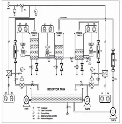
Fig. 1. Diagrammatic representation of Three tank interacting system
Diagrammatic representation of Three tank interacting system shown in the Fig. 1. can be viewed as a prototype of many industrial process applications which acts as a bench mark system for fault tolerant control. It has equal cross section area and each tank is assumed to be a first order system which are connected in interacting mode. The three tank interacting system is a highly non-linear process because of the interaction between the tanks. Here the challenging task controlling of the nonlinear process. In this work, the performance analysis is made for both PID and Observer based controller for three tank interacting system in- order to sustain the level of the third tank at set point value with respective of the changes in inflow of the first tank.
Research of Conventional and Observer
Based Controller for Three Tank Interacting
System
II. MATHEMATICAL MODELING OF THREE TANK SYSTEM WITH SISO CONFIGURATION A. ARX MODELING - Nonlinear ARX Model cause to cover wider area than the Linear ARX Structure
A nonlinear ARX model can be understood as an linear model expansion. A linear Single Input Single Output Auto Regressive model has this structure which is mentioned in the Equation (1)
y(t) + a1y(t - 1) + a2y(t - 2) + …… + anay(t - na) = b1u(t) + b2u(t - 1) + ……+ bnbu(t - nb + 1) + e (t)
(1) Where, nk the input delay is zero to remove the complexities of the notation.
The structure suggests that the current output y(t) is stated or estimated as a weighted sum of past output, current and past input values. Rewriting the equation as a multiple which is given as Equation (2)
Yp(t) = [-a , -a , ……,-a , b , b , ……, b ]*[y(t-1), y(t-2), 1 2 na 1 2 nbT y(t-na), u(t), u(t-1), ……, u(t – nb-1)]
(2) Wherey(t−1),y(t−2),...,y(t−na),u(t),u(t−1),...,u(t – nb−1) are delayed input and output variables and it is called as regressors. The linear ARX model then identifies yp, the current output as a weighted sum of its regressors.
This structure can be extended to generate a nonlinear form as:
Instead of the weighted sum it constitutes a linear mapping, the ARX nonlinear model has an adaptable nonlinear mapping function.
yp(t)=f(y(t−1),y(t−2),y(t−3),.,u(t),u(t−1),u(t−2),..) (3) where f is the nonlinear function which is mentioned in the Equation (3) Inputs to f are model regressors.
B. Nonlinear AutoRegressive Model Structure
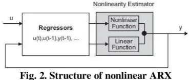
[image:2.595.75.261.530.609.2]The block diagram representation of the nonlinear ARX model structure in a simulation scenario is shown in Fig. 2.
Fig. 2. Structure of nonlinear ARX
III. DESINGING OF CONTROLLERS FOR THREE
TANK INTERACTING SYSTEM A. Proportional Integral Derivative Controller Design
Fig. 3. Block diagram of a Proportional Integral Derivative controller in a feedback loop
The above Fig. 3. shows the block diagram of PID Controller. The controller strives to reduce the error over time by adjusting the control variable, such as the control valve position, a damper, or the power supplied to the heating element, to a new value established by a weighted sum. The below Equation (4) is the equation for PID controller.
t
de(t)
u(t)
kpe(t)
ki
e(t) dt
kd
dt
,
(4)B. Observer Based Controller Design
Consider the completely controllable and completely observable system defined by the Equation (5)
= Ax + bu (5)
y = cx
Suppose we have designed a state-feedback control law Equation (6)
u = -kx (6)
Full order observer design Equation (7) is
= A + bu + m(y – c ) (7)
Verica Radisavljevic-Gajic [9] described the State- feedback control based on the observed state Equation (8) is
u = -k (8)
The state is checked for its controllability and observability. And hence the system is controllable and observable for the obtained Hammerstein wiener state space model. Therefore by assigning the desired poles, initial conditions, observable conditions we obtain the observer based controller design.
The Combined state feedback control and state estimation system has the plant and sensor. The output from the sensor is given to the observer. The output from the observer is given to the control law, then the output from the control law is given as an input to the plant. Together the observer and control law is called as compensator.
u(t) = -kx(t) + Nr (9)
The above Equation (9) is the control law equation which is used to design observer based controller.
International Journal of Innovative Technology and Exploring Engineering (IJITEE) ISSN: 2278-3075, Volume-8, Issue- 6S4, April 2019
The above shown Fig. 4. is the combined state feedback control and state estimation. Therefore, the observer based controller can be designed by applying the state space values of the Hammerstein wiener model.
IV. RESULTS AND DISCUSSIONS OF THE
PROPOSED SYSTEM
A. Response of Open Loop Three Tank Interacting System with SISO Configuration
Input and output data is collected using MATLAB and then the data is stored into workspace files. These datas are then imported to the Toolbox of System Identification in MATLAB software. The transfer function of the process is obtained in the form of process model as FOPDT form given below.
G(s)=
e-
tdsG(s) = (10)
[image:3.595.337.515.96.239.2]Response of Open Loop three tank interacting system with Single Input Single Output configuration is shown in Fig. 5.
Fig. 5. Response of Open Loop three tank interacting system with Single Input Single Output configuration B. Output of ARX Model
[image:3.595.329.522.355.581.2]The below Fig. 6. represents the State space representation of the model.
Fig. 6. Nonlinear ARX state space model
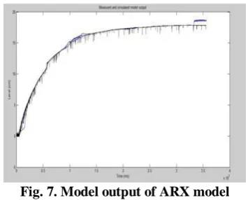
The below response shown in the Fig. 7. shows the model output of ARX model and the open loop response of three tank interacting system.
Fig. 7. Model output of ARX model
Therefore, the mathematical modeling of the Proposed system with Single Input Single Output configuration is obtained using ARX modeling and it is shown in the above Fig. 7.
C. Hammerstein Wiener Model Output
Nonlinear Hammerstein wiener model with Single Input Single Output configuration is displayed in the below Fig. 8.
Fig. 8. State space model of Hammerstein wiener model
Hammerstein wiener model is chosen because the three tank interacting system is of order three and therefore, we apply the state space model of Hammerstein wiener to design state observer.
D. PID Controller
[image:3.595.61.279.357.506.2] [image:3.595.56.281.579.745.2]Fig. 9. Closed loop response of PID controller E. Observer Based Controller Design in MATLAB Script
The MATLAB coding for obtaining the observer based controller design is made by applying the A,B,C,D matrix of the equation of State Space. Then the desired pole values are given where the system poles will lie. Obtain the value of gain k. Find the system whether it is controllable and observable by giving the appropriate coding. Give the initial conditions and also the observer poles should be three to five times of the desired poles value. Find the observer gain values L by applying suitable coding. Finally, the observer based controller is designed only if the system is both controllable and observable. Hence the system is observable and controllable as its rank is 3. Apply these values like A,B,C,D,K,L in the simulink model.
F. Observer Design In Simulink Model
The observer based Controller makes an attempt to reduce the error by adjusting the controller output. If the set -point is given as 15 cm, it settles at the desired set point. The below Fig. 10. shows the set point tracking of observer based controller design.
Fig. 10. Response of observer based controller design G. Comparison of PID and Observer Based Controller
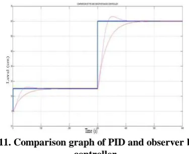
[image:4.595.64.272.48.205.2]The below Fig. 11. shows the comparison graph of PID and observer based controller for three tank interacting system.
Fig. 11. Comparison graph of PID and observer based controller
H. Performance Analysis of the Controllers
The performance analysis of the controllers are identified by differentiating the Response Rise time, Settling time, Peak time and peak overshoot value. The results are tabulated below in the Table 1.
TABLE I. PERFORMANCE ANALYSIS OF PID AND OBSERVER BASED CONTROLLER FOR THREE
TANK INTERACTING SYSTEM
Parameters PID Controller Observer Based Controller
Rise time (s) 32.5 153
Settling time (s) 128 168
Peak time (s) 54 0
Peak overshoot (%) 7 0
From the Table 1. The performances are analyzed for both the controllers for different parameters. PID controllers are conventionally used for level control process. But observer based Controller has got its peak overshoot and peak time value as zero compared to that of the conventional PID controller. Therefore, the observer based controller performance is better than the conventional PID controller.
V. CONCLUSION AND RESULTS
A. Conclusion about the work
Here, if the sensor of three tank Interacting system is failed at the point of stability, it is replaced by the state observer.In this project, the problem of observer based controller is investigated for the three tank interacting system with SISO configuration.
[image:4.595.62.277.477.627.2]International Journal of Innovative Technology and Exploring Engineering (IJITEE) ISSN: 2278-3075, Volume-8, Issue- 6S4, April 2019
B. Future Scope
Here, by designing the Observer, the design of observer based controller is done by finding the control law and feed forward gain value for the three tank interacting system in simulation.
Therefore, the design of observer and observer based controller can be implemented in real time for the future work of the three tank interacting system. The State observer will act as the sensor as soon as the plant sensor gets failed at the point of stability.
REFERENCES
1. AnuradhaKodali, Yilu Zhang, Chaitanya Sankavaram,
KrishnaPattipati, and Mutasim Salman (2013), “Fault Diagnosis in the Automotive Electric Power Generation and Storage System (EPGS)”, IEEE/ASME Transactions on Mechatronics, Vol. 18, No. 6. pp. 1809-1818.
2. Bin Jiang and Fahmida N. Chowdhury (2005), “Fault Estimation and Accommodation for Linear MIMO Discrete-Time Systems”, IEEE Transactions on Control Systems Technology, Vol. 13, No. 3. pp. 493 - 499.
3. BoZ. Q., R. K. Aggarwal, A. T. Johns, H. Y. Li, Y. H. Song, R. L. King,D. Novosel, and M. Kezunovic (1997), “A new approach to phase selectionusing fault generated high frequency noise and neural networks”,IEEETrans. Power Del., vol. 12, no. 1, pp. 106–115.
4. Chakrabarti A , Sharma N, Singh K, Banik P , Patwari R, Bhattacharjee S. , Das B and Kasari P.R. (2012), “Observer Based State Feedback Control of DC Machine”, IEEE. 5. HajjarA. A., M. M. Mansour, and H. A. Talaat (2004)
“High-phase orderpower transmission lines relaying approach based on the wavelet analysisof the fault generated traveling waves”, in Proc. 39th Int. Univ.Power Eng. Conf., vol. 1, pp. 805–809. 6. Littler T. B. and D. J. Morrow (1999), “Wavelets for the analysis and compression of power system disturbances”, IEEE Trans. Power Del., vol. 14,no. 2, pp. 358–364.
7. Silva K. M., B. A. Souza, and N. S. D. Brito (2006), “Fault detection and classification in transmission lines based on wavelet transform and ANN”,IEEE Trans. Power Del., vol. 21, no. 4, pp. 2058–2063.
8. SuQ. L., X. Z. Dong, Z. Q. Bo, and F. Jiang (2002), “N ew approach of faultdetection and fault phase selection based on initial current traveling waves”, in Proc. IEEE Power Eng. Soc. Summer Meeting, vol. 1,pp. 393–397.
9. Verica Radisavljevic-Gajic (2014), “Linear Observers Design and Implementation”, Proc. of 2014 Zone 1 Conference of the American Society for Engineering Education (ASEE Zone 1), IEEE.
10. Xiangjun Zeng, K. K. Li, W. L. Chan, Sheng Su, and Yuanyuan Wang (2008), “Ground-Fault Feeder Detection With Fault-Current and Fault- Resistance Measurement in Mine Power Systems”, IEEE Transactions on industry applications,vol. 44,no. 2.pp. 1259-1274.
11. R. BharathaSuriyan, M. Prabhakaran, P. Venkadesan (2016), “Design of
12. Flexible and Cost Effective Universal DAQ Device for Remote
13. Monitoring and Control of Industrial Processes”,
International Journal of Advanced Research in Electrical,
Electronics and Instrumentation Engineering, Vol. 5, No. 5,
pp. 4254-4261.
14. P. Naveen kumar and M. Prabakaran (2016), ”Design of Model Predictive Controller for Industrial Pressure”
International Journal of Engineering Science and Computing,
Vol. 6, No. 5, pp. 5724- 5727.
15. M. Prabhakaran, S. Kanthalakshmi (2018), “Analysis of Three tank interacting system with observer based controller” Journal of Control and Instrumentation. Vol.9, No.1, pp.
17-16. V. Sathya, M. Prabhakaran, D. Angeline Vijula, P. Venkadesan (2016), “Empirical Modeling and controller design for TITO level System”, International Journal of
Engineering Sciences & Research Technology, Vol. 5, No. 5,
pp. 497 – 503.